
UV2400U Air Purifier
with AirBRIGHT™ Odor Absorption
Installation
Instructions

2
Before Installing this Product
Read these instructions carefully; failure to follow them could damage the product and
cause a hazardous situation.
Installer must be a trained, experienced service technician.
WARNING: UV Light Hazard.
Harmful to bare skin and eyes. Can cause temporary or permanent loss of
vision. Never look at lamps while illuminated.
• To prevent exposure to ultraviolet light, disconnect power to the ultraviolet air
treatment system before servicing any part of the heating/air conditioning system.
• View illumination only through lamp handle or sight glass.
• Do not attempt to bypass duct mount switch.
• Do not attempt to open housing; unit is sealed to prevent ultraviolet light
exposure.

3
CAUTION: Personal Injury Hazard. HVAC power supply can cause
electrical shock.
Disconnect HVAC power supply before installing, cleaning or replacing ultraviolet
lamp(s).
CAUTION: Breakable Glass Hazard. Can cause personal injury.
• Be careful when inserting lamp(s) into lamp base.
• Wear protective gloves when handling lamp(s).
CAUTION: Personal Injury Hazard. Power supply can cause electrical
shock.
• Disconnect power supply before cleaning or replacing ultraviolet lamp(s).
• Do not open base unit or lamp handle; there are no user-serviceable compo-
nents inside.
CAUTION: UV Lamp Burn Hazard. Harmful to bare skin. Can cause severe
burns.
• Disconnect power 15 minutes before removing ultraviolet lamp(s).

4
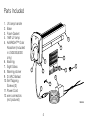
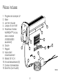
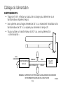
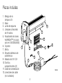
1. UV lamp handle
2. Base
3. Foam Gasket
4. 16W UV lamp
5. AirBRIGHT™ Odor
Absorber (included
in UV2400U5000
only)
6. Bushing
7. Sight Glass
8. Warning sticker
9. 24 VAC Ballast
10. Self Tapping
Screws (3)
11. Power Cord
12. wire connectors
(not pictured)
Parts Included
4
5
2
11
9
1
8
M34596
3
7
10
6

5
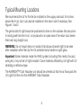
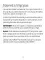
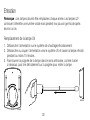
Typical Mounting Locations
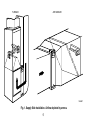
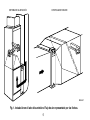
We recommend the UV Air Purifier be installed on the supply side duct 3–5 inches
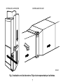
above the A-coil, but it can also be installed on the return side if necessary. See
Figures 1 and 2.
The germicidal UV light should be positioned to shine on the surfaces that are prone
to mold growth like the A-coil, or be placed in an open area of the return duct where
there are long straight runs.
WARNING: Do not mount device in location that allows ultraviolet light to be seen
after installation other than by the UV protected lamp handle or sight glass.
Important: Some materials inside the HVAC system (including filter media, flex duct,
wiring etc.) may not be UV light resistant. Cover materials affected by UV light with UV
shielding or reflective tape.
The AirBRIGHT™ Odor Absorber unit should be oriented so that the air flows past the
UV Light first then into the AirBRIGHT Odor Absorber.

6
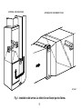
Fig. 1. Supply Side installation. Airflow depicted by arrows.
M34597
FURNACE AIR HANDLER

7
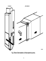
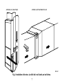
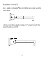
Fig. 2. Return Side installation. Airflow depicted by arrows.
M34621
FURNACE
AIR HANDLER

8
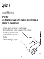
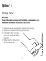
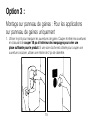
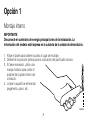
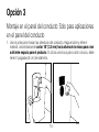
Option 1
Internal Mounting
IMPORTANT
Turn off main power source before installation. Model information is
printed on the Power Unit cover.
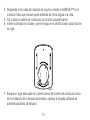
1. Unfasten panel to gain access to mounting location
2. Determine the optimal position for placement of the Air Purifier.
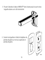
3. If necessary, use a utility knife to
cut the insulation on the inside of
the duct.
4. Clean surface of glue, dust, etc.
M34659

9
M34689
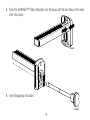
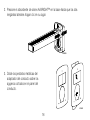
5. Push the AirBRIGHT™ Odor Absorber into the base until the two tabs on the side
click into place.
6. Insert Snaplamp into base.
M34685

10
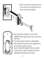
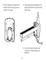
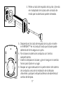
8. Place the magnetic bars on the base
directly on the clean metal surface.
M34661
7. Rotate the lamp handle clockwise
until it snaps in place.
9. Use foil tape to close the cut in the
insulation as needed.
M34660

11
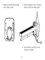
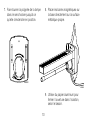
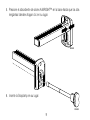
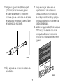
10. Create a 5/8 (0.625) in. hole in the
duct and pass the cord through it. Clip
the bushing provided onto the cord at
a point close to the hole. Plug the hole
with the bushing.
M34601
M34602
12. Find a suitable location on the
outside of the duct-work near the
UV Lamp installation and apply the
warning/lamp replacement sticker.
13. Drill a 1/2 in. hole through the circle
on the sticker. Press the UV sight
glass into hole.
11. Secure access panel to the duct work.

12
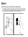
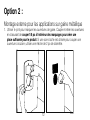
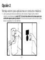
Option 2
External Mounting for Metal Duct Applications
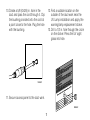
1. Use the gasket to mark the duct openings. Cut and remove openings, making sure
to cut 1/8-inch outside of the markings to create enough room for the product. If
using a hole saw to cut circular opening, use a 2-inch diameter bit.
M34604

13
M34687
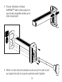
2. Push the AirBRIGHT™ Odor Absorber
into the base until the two tabs on the
side click into place.
M34685
3. Remove one side of the backing from the gasket and stick
gasket on the ductwork so that the openings line up.

14
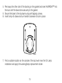
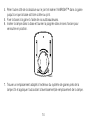
4. Peel away the other side of the backing on the gasket and insert AirBRIGHT™ into
the duct until the base sticks securely to the gasket.
5. Secure the base to the ductwork using self-tapping screws.
6. Insert lamp into base and turn handle clockwise to lock in place.
M34661
7. Find a suitable location on the outside of the duct-work near the UV Lamp
installation and apply the warning/lamp replacement sticker.

15
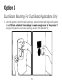
Option 3
Duct Board Mounting: For Duct Board Applications Only
1. Use the gasket to mark the duct openings. Cut and remove openings, making sure
to cut 1/8-inch outside of the markings to create enough room for the product. If
using a hole saw to cut circular opening, use a 2-inch diameter bit.
M34604

16
M34853
M34685
M34685
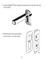
2. Push the AirBRIGHT™ Odor Absorber into the base until the two tabs on the side
click into place.
3. Bend metal tabs of duct board adapter
over the holes cut in the duct board.

17
M34852
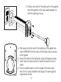
4. Remove one side of the backing from the gasket
and stick gasket on the duct board adapter so
that the openings line up.
5. Peel away the other side of the backing on the gasket and
insert AirBRIGHT into the duct until the base sticks securely
to the gasket.
6. Secure the base to the ductwork using self tapping screws.
7. Insert lamp into base and turn handle clockwise to lock in
place.
8. Find a suitable location on the outside of the duct-work
near the UV Lamp installation and apply the warning/lamp
replacement sticker.
M34661

18
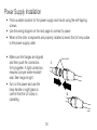
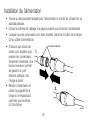
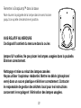
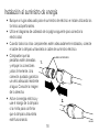
Power Supply Installation
• Find a suitable location for the power supply and mount using the self-tapping
screws.
• Use the wiring diagram on the next page to connect to power.
• When all the other components are properly installed connect the UV lamp cable
to the power supply cable.
M34663
ALIGN FLANGES
2.
1.
• Make sure the flanges are aligned
and then push the connectors
firmly together. A tight connection
ensures a proper water-resistant
seal. See image at right.
• Turn on the power and use the
lamp handle or sight glass to
confirm that the UV Lamp is
operating.

19
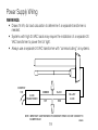
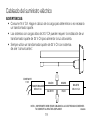
Power Supply Wiring
WARNINGS:
• Draws 16 VA, do load calculation to determine if a separate transformer is
needed.
• Systems with high 24 VAC loads may require the installation of a separate 24
VAC transformer to power the UV light.
• Always use a separate 24 VAC transformer with “communicating” air systems.
M34605
NOTE: IMPORTANT! MUST BE WIRED TO CONSTANT POWER. DO NOT CONNECT TO
BLOWER RELAY.
24 VAC
TRANSFORMER
BALLAST
24 VAC
COMMON
HOT
BLACK
RED
CONSTANT
110V

20
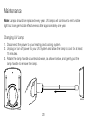
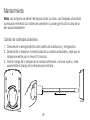
Maintenance
Note: Lamps should be replaced every year. UV lamps will continue to emit visible
light but lose germicidal effectiveness after approximately one year.
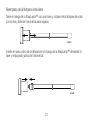
Changing UV Lamp
1. Disconnect the power to your heating and cooling system.
2. Unplug or turn off power to your UV System and allow the lamp to cool for at least
15 minutes.
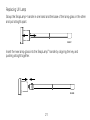
3. Rotate the lamp handle counterclockwise, as shown below, and gently pull the
lamp handle to remove the lamp.
M34606
M34609
La page est en cours de chargement...
La page est en cours de chargement...
La page est en cours de chargement...
La page est en cours de chargement...
La page est en cours de chargement...
La page est en cours de chargement...
La page est en cours de chargement...
La page est en cours de chargement...
La page est en cours de chargement...
La page est en cours de chargement...
La page est en cours de chargement...
La page est en cours de chargement...
La page est en cours de chargement...
La page est en cours de chargement...
La page est en cours de chargement...
La page est en cours de chargement...
La page est en cours de chargement...
La page est en cours de chargement...
La page est en cours de chargement...
La page est en cours de chargement...
La page est en cours de chargement...
La page est en cours de chargement...
La page est en cours de chargement...
La page est en cours de chargement...
La page est en cours de chargement...
La page est en cours de chargement...
La page est en cours de chargement...
La page est en cours de chargement...
La page est en cours de chargement...
La page est en cours de chargement...
La page est en cours de chargement...
La page est en cours de chargement...
La page est en cours de chargement...
La page est en cours de chargement...
La page est en cours de chargement...
La page est en cours de chargement...
La page est en cours de chargement...
La page est en cours de chargement...
La page est en cours de chargement...
La page est en cours de chargement...
La page est en cours de chargement...
La page est en cours de chargement...
La page est en cours de chargement...
La page est en cours de chargement...
La page est en cours de chargement...
La page est en cours de chargement...
La page est en cours de chargement...
La page est en cours de chargement...
La page est en cours de chargement...
La page est en cours de chargement...
La page est en cours de chargement...
La page est en cours de chargement...
La page est en cours de chargement...
La page est en cours de chargement...
La page est en cours de chargement...
La page est en cours de chargement...
La page est en cours de chargement...
La page est en cours de chargement...
La page est en cours de chargement...
La page est en cours de chargement...
-
 1
1
-
 2
2
-
 3
3
-
 4
4
-
 5
5
-
 6
6
-
 7
7
-
 8
8
-
 9
9
-
 10
10
-
 11
11
-
 12
12
-
 13
13
-
 14
14
-
 15
15
-
 16
16
-
 17
17
-
 18
18
-
 19
19
-
 20
20
-
 21
21
-
 22
22
-
 23
23
-
 24
24
-
 25
25
-
 26
26
-
 27
27
-
 28
28
-
 29
29
-
 30
30
-
 31
31
-
 32
32
-
 33
33
-
 34
34
-
 35
35
-
 36
36
-
 37
37
-
 38
38
-
 39
39
-
 40
40
-
 41
41
-
 42
42
-
 43
43
-
 44
44
-
 45
45
-
 46
46
-
 47
47
-
 48
48
-
 49
49
-
 50
50
-
 51
51
-
 52
52
-
 53
53
-
 54
54
-
 55
55
-
 56
56
-
 57
57
-
 58
58
-
 59
59
-
 60
60
-
 61
61
-
 62
62
-
 63
63
-
 64
64
-
 65
65
-
 66
66
-
 67
67
-
 68
68
-
 69
69
-
 70
70
-
 71
71
-
 72
72
-
 73
73
-
 74
74
-
 75
75
-
 76
76
-
 77
77
-
 78
78
-
 79
79
-
 80
80


Honeywell UV2400U5000 Guide d'installation
- Taper
- Guide d'installation
- Ce manuel convient également à
dans d''autres langues
Documents connexes
-
Honeywell UV100RM TrueUV Manuel utilisateur
-
-
-
-
-
-
Honeywell TrueSTEAM HM506 Manuel utilisateur
-