
Operations Manual
Manuel d’opérations
Gladiator512, 512 Ride-On, 712
Sweepers/Balayeuses
Code: 19674 (512) / 19675 (512 Ride-On) / 19673 (712)
Serial Number:
Numéro de série : _____________________
Date of Purchase:
Date d’achat : ________________________
More info / Plus d’info : www.dustbane.ca
2015-10


3
ENGLISH
General Information
Read this manual carefully before carrying out any work on the machine.
Scope Of The Manual
This manual has been written by the Manufacturer and is an integral part of the machine. It denes the purpose for which the
machine has been designed and constructed and contains all the information required by operators. In addition to this manual
containing all user information, other publications are available providing specic information for maintenance personnel.
Constant respect for the instructions ensures the safety of the operator and the machine, low running costs and high quality results
and extends the working life of the machine. Failure to respect the instructions may lead to damage to the operator, machine, oor
and environment.
Parts of the text requiring special attention are highlighted in bold and preceded by the symbols illustrated and described here.
In line with the company’s policy of constant product development and updating, the Manufacturer reserves the right to make
modications without warning.
Documentation Provided With The Machine
• Operations Manual
• Parts List
• EC certicate of conformity.
Technical Information
General Description
This machine is a motorized sweeper designed to sweep oors in commercial and industrial premises. The sweeper may be used
to clean the residues from industrial processes, dust and dirt in general on all relatively even at hard surfaces such as concrete,
asphalt, porcelain stoneware, ceramic tiles, sheet metal, marble, embossed or smooth rubber or plastic mats indoors or outdoors.
Legend
A

4
ENGLISH
B
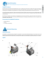
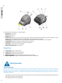
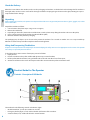
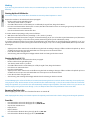
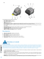
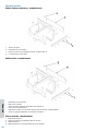
The main parts of the machine are as follows (g. A):
• Front bin (g. A / B, ref. 2).
• Rear bin (g. A / B, ref. 1).
• Display (g. A, ref. 3).
• Center brush (g. A / B, ref. 4), the principal organ of the machine, transfers the dust and debris to the bin. Available in a range
of hardnesses and with dierent bristles, according to the type of material to be picked up.
• Side brush (g. A / B, ref. 5), conveys the dust and debris, used exclusively to clean edges, corners and proles.
• Suction lter (g. A / B, ref. 6), lters air drawn in by the suction fan.
• Suction fan, enables the machine to sweep without raising dust.
• Filter shaker, used to clean the suction lter.
• Battery charger display (g. A / B, ref. 7).
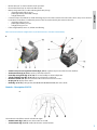
Danger Zones
A. Control panel: danger of short circuit.
B. Center brush: danger due to brush rotation.
C. Side brush: danger due to brush rotation.
D. Back/front wheels: danger of crushing between the wheel and chassis.
E. Motor compartment: danger of short circuit between the poles of the battery.
Safety Information
Safety Regulations
Read the “User manual” carefully before start-up and use, or before performing maintenance or any other work on the machine.
Rigorously respect all instructions in the Manual (in particular those relating to danger and important information) and on the
safety plates fitted to the machine. The Manufacturer declines all liability for damage to people or things resulting from failure to
observe the instructions.
• The appliance must be used exclusively by persons trained in its use and/or who have demonstrated their ability and have been
expressly instructed to use the appliance.
• The machine must not be used by minors.

5
ENGLISH
• The machine must not be used for purposes other than those for which it was expressly designed. Scrupulously respect all
safety standards and conditions applicable to the type of building in which the machine is to be operated (eg: pharmaceutical
companies, hospitals, chemicals, etc).
• DO NOT use the machine in places with inadequate lighting or explosive atmospheres, on public roads, in the presence of dirt
hazardous to health (dust, gas, etc) and in unsuitable environments.
• The machine is designed for use at temperatures of between +4°C and +35°C. When the machine is not being used, the
temperature range is +0°C and +50°C.
• The machine is designed to work in a humidity of between 30% and 95%.
• NEVER pick up ammable liquids or explosives (eg. petrol, fuel oil, etc), acids and solvents (eg. paint solvents, acetone etc.).
NEVER pick up aming or incandescent objects.
• NEVER use the machine on slopes or ramps of more than 2%. In the case of slight slopes, do not use the machine transversally,
always maneuver with care and do not reverse.
• When transporting the machine on steeper ramps or slopes, take the utmost care to avoid tipping up and/or uncontrolled
acceleration.
• NEVER park the machine on a slope.
• The machine must never be left unattended with the motor on. Before leaving it, turn the motor o, make sure it cannot move
accidentally.
• ALWAYS pay attention to other people, children in particular, present in the place where you are working.
• NEVER use the machine to transport people or things or to tow anything not permitted by the manufacturer. Do not tow the
machine.
• NEVER rest objects of any weight on the machine for any reason.
• NEVER obstruct ventilation and heat dispersion slits.
• NEVER remove, modify or circumvent safety devices.
• Numerous unpleasant experiences have shown that a wide range of personal objects may cause serious accidents. Before
beginning work, remove jewelry, watches, ties, etc.
• The operator must always use personal protection devices: protective apron or overalls, non-slip waterproof shoes, rubber
gloves, protective goggles and ear protectors and mask to protect the respiratory tract.
• Keep the hands away from moving parts.
• In the case of malfunction and/or faulty operation, turn the machine o immediately and do not tamper. Contact a service
center authorized by the Manufacturer.
• All maintenance operations must be performed in an adequately lit place.
• All work on the electrical system and all maintenance and repair operations other than those explicitly described in this manual
must be performed by specialized personnel expert in the sector only.
• Only original accessories and spare parts supplied by the Manufacturer may be used in order to guarantee safe problem-free
operation of the machine. Never use parts removed from other machines or from other kits.
• This machine has been designed and constructed to provide ten years’ service from the fabrication date shown on the rating
plate. After this time, whether the machine has been used or not, it should be disposed of according to current legislation in
the country in which it is used:
• The product is classied as WEEE type special waste and is covered by the requisites of the new environmental protection
regulations (2002/96/CE WEEE). It must be disposed of separately from ordinary waste in compliance with current legislation
and standards.
• Special waste. DO NOT dispose of with ordinary waste.
• If you decide to stop using the machine, you are recommended to remove the batteries and dispose of them at an authorized
collection center.
• You should also make sure that all parts of the appliance which could represent a hazard, particularly to children, are made safe.
Handling And Installation
Lifting And Transporting The Packaged Machine
During all lifting operations, make sure the packaged machine is rmly anchored to avoid it tipping up or being accidentally dropped.
Always load/unload lorries in adequately lit areas.
The machine, packaged on a wooden pallet by the Manufacturer, must be loaded using suitable equipment. A fork lift truck must
always be used to lift the packaged body of the machine. Handle with care to avoid knocking or overturning the machine.

6
ENGLISH
Checks On Delivery
When the carrier delivers the machine, make sure the packaging and machine are both whole and undamaged. If the machine is
damaged, make sure the carrier is aware of the damage and before accepting the goods. Reserve the right (in writing) to request
compensation for the damage.
Unpacking
When unpacking the machine, the operator must be provided with the necessary personal protection devices (gloves, goggles, etc) to limit
the risk of accident.
Unpack the machine as follows:
1. Cut and remove the plastic straps using scissors or nippers;
2. Remove the cardboard;
3. Depending on the model, remove the metal brackets or cut the plastic straps xing the machine chassis to the pallet;
4. Using a sloping ramp, push the machine backwards o the pallet;
5. Move the machine away from the packaging.
The packaging may be kept as it can be reused to protect the machine if it is moved to another site or to a repair workshop.
Otherwise it must be disposed o in compliance with current legislation.
Lifting And Transporting The Machine
All phases must be performed in an adequately lit room and adopting the safety measures most appropriate to the situation. The operator
must always use personal protection devices.
To load the machine onto a means of transport, proceed as follows:
1. Empty the bin.
2. Place the machine on the pallet and x it with plastic straps or metal brackets;
3. Lift the pallet (with the machine) using a fork lift truck and load it onto the means of transport;
4. Anchor the machine to the means of transport with cables connected to the pallet and machine itself.
Practical Guide For The Operator
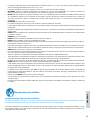
Controls – Description512 Ride-On
The machine has the following controls and indicator lights:
• On/OFF switch (ref. 1): turns the machine on and o.
• Emergency button (g. A, ref. 16): enables/disables all functions of the machine.
• Suction button (ref. 2): enables/disables the suction function.

7
ENGLISH
• Brush button (ref. 3): enables/disables brush operation.
• Filter shaker button (ref. 4): enables the lter shaker.
• Battery charge LED (ref. 5): 3 LEDs indicating the battery charge:
• green light battery fully charged
• yellow light battery almost at, recharge
• red light battery at
• Center brush pressure LED (ref. 6): 6 LEDs indicating the pressure of the center brush on the work surface. The pressure exerted
by the brush on the oor is calculated by means of the current absorbed by the center brush motor:
• green lights, light pressure
• yellow light, medium pressure
• red light, heavy pressure
• If the red light (LED 6) comes on, all LEDs start ashing.
Note: Two minutes after the red light comes on, the brush function is shut down automatically.
A
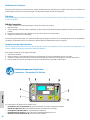
• Center brush pressure regulation handle (g. A, ref. 8): regulates the pressure of the brush on the oor.
• Accelerator knob (g. A, ref. 9): sets the speed of the machine.
• Front ap raising knob (g. A, ref. 10): raises the front ap to collect bulky debris.
• Side brush lifting lever (g. A, ref. 11): raises and lowers the side brush.
• Direction selector (ref. 7): sets movement of the machine to forwards or reverse.
• Display (ref. 8): displays alarm codes.
• Brake (g. A, ref. 12): parking brake (ACTIVATED VIA THE WHITE LEVER) and service brake.
Controls – Description512-712
C
The machine has the follow controls and indicator lights:
• On/OFF switch (g. C, ref. 1): turns the machine on and o.
• Suction button (g. C, ref. 2): enables/disables the suction function.

8
ENGLISH
• Filter shaker button (g. C, ref. 4): enables the lter shaker.
• Battery charge LED (g. C, ref. 5): 3 LEDs indicating the battery charge:
• green light: battery fully charged
• yellow light: battery almost at, recharge
• red light: battery at
• Suction LED (g. C, ref. 9): indicates the suction status ON/OFF.
• Center brush pressure regulation handle (ref. 8): regulates the pressure of the brush on the oor.
• Drive knob (ref. 9): enables the drive of the machine.
• Front ap raising knob (ref. 10): raises the front ap to collect bulky debris.
• Side brush lifting lever (ref. 11): raises and lowers the side brush.
• Brake (ref. 12): parking brake
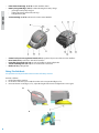
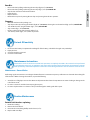
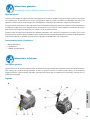
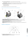
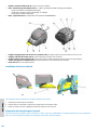
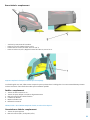
Fitting The Side Brush
This operation must be performed with the machine o and key removed
Proceed as follows:
1. Lift the front of the machine.
2. Fit the brush and x it in place with the washer and screw provided (g D, ref. 1).
3. Unscrew the two screws (g. E, ref. 1), adjust the height of the brush and tighten the screws again.
D
E

9
ENGLISH
Preparing The Machine For Work
Before starting work, wear overalls, ear protectors, non-slip shoes, mask to protect the respiratory tract, gloves and all other personal pro-
tection devices necessitated by the work environment.
Batteries: installation And Connection
The batteries are normally supplied lled with acid and ready for use. If the batteries are dry, before mounting them on the machine,
proceed as follows:
• Remove the caps and ll all elements with specic sulphuric acid solution until the plates are entirely covered (this requires at
least a couple of passes for each element);
• Leave for 4-5 hours to allow the air bubbles to come to the surface and the plates to absorb the electrolyte;
• Make sure the level of electrolyte is still above the plates and if necessary top up with sulphuric acid solution;
• Close the caps;
• Mount the batteries on the machine (following the procedure described below). Before starting up the machine the rst time,
charge the batteries.
Check that all switches on the control panel are in the “0” (o) position. Make sure you connect the terminals marked with a “+” to the
positive poles of the battery. Do not check the battery charge by sparking. Meticulously follow the instructions given below as short
circuiting the batteries could cause them to explode.
1. Rotate the top cowling through 90° towards the back of the machine.
2. Place the battery/ies into the compartment.
3. Connect the battery/ies.
Mount the batteries on the machine using means suitable for their weight. The positive and negative poles have dierent diameters.
• Rotate the top cowling.
• When using the machine, follow the instructions below.
Batteries: Removal
When removing the batteries, the operator must be equipped with suitable personal protection devices (gloves, goggles, overalls, safety
shoes, etc) to reduce the risk of accidents. Make sure the switches on the control panel are in the “0” position (o) and the machine is turned
o. Keep away from naked ames, do not short circuit the battery poles, do not cause sparks and do not smoke. Proceed as follows:
• Disconnect the battery wiring and bridge terminals from the battery poles.
• If necessary, remove the devices xing the battery to the base of the machine.
• Lift the batteries from the compartment using suitable lifting equipment.
The Battery Charger
Never allow the batteries to become excessively at as this could damage them irreparably.
Choosing The Battery Charger
Make sure the battery charge is compatible with the batteries to be charged.
• Tubular lead batteries: you are recommended to use an automatic battery charger. However, you should always consult the
battery charger manufacturer and manual to conrm the choice.
• Gel batteries: use a charger specic for this type of battery.
Preparing The Battery Charger
If you wish to use a battery charger not provided with the machine, you must t it with the connector supplied with the machine.
To install the connector, proceed as follows:
• Remove about 13 mm of protective sheath from the red and black wires of the battery charger;
• Insert the wires into the connector contacts and squeeze them forcefully with suitable pliers;
• Respect the polarity (red wire + black wire –) when inserting the wires into the connector.
• Insert the wired-up connector into the connector in the machine compartment.

10
ENGLISH
Working
If you are using the machine for the rst time, we recommend trying it on a large obstacle-free surface rst to acquire the necessary
familiarity.
Starting Up/Use 512 Ride-On:
The seat has a safety sensor which allows the machine to move only when the operator is seated.
Prepare the machine as described in the above paragraph.
• Lift the side brush using the lifting lever.
• Turn the key switch to the “1” position.
• Check the LEDs to make sure the battery/ies is suciently charged. If not, charge the batteries.
• Press the brush button when the brushes are active, the LED on the button comes on. Pressing it again stops the brushes, the
suction motor comes on automatically.
• Use the accelerator knob to activate the drive.
To set the maximum operating speed, proceed as follows:
1. With the machine o, turn the key switch (g. C, ref. 1) to the “1” position.
2. Move forwards with the machine using the accelerator knob (g. A, ref. 9) to select the required maximum speed, then move
the drive selector (g. C, ref. 7) to the centre position. Memorising of the speed is indicated by a beep.
To reset the maximum operating speed set by the manufacturer, turn the machine on and o using the key switch (g. C, ref. 1) or
repeat the instructions in point 2, turning the accelerator knob (g. A, ref. 9) as far as it will go (MAX. SPEED). Reverse speed cannot
be changed.
• Adjust pressure of the centre brush on the oor using the knob according to the type of oor and dirt to be picked up. Turn it
clockwise to increase pressure and anticlockwise to reduce pressure on the work surface.
• Lower the side brush using the lever.
• Start cleaning, manoeuvering the handgrip with the hands and acting on the drive control.
Starting Up/Use 512-712
• Prepare the machine as described in the above paragraph.
• Lift the side brush using the lifting lever.
• Turn the key switch to the “1” position.
• Check the LEDs to make sure the battery/ies is fully charged. If not, charge the batteries.
• Use the lever to activate the drive.
• Press the suction button.
• Adjust pressure of the center brush on the oor using the knob according to the type of oor and dirt to be picked up. Turn it
clockwise to increase pressure and anticlockwise to reduce pressure on the work surface.
• Lower the side brush using the lever.
• Start cleaning, maneuvering the handgrip with the hands and acting on the drive control.
To avoid damaging the surface of the oor to be treated, avoid rotating the brushes with the machine stationary. Do not pick up wire,
string or plastic straps. Each 30 minutes of work, activate the lter shaker button (g. C, ref. 4) for 30 seconds to clean the suction lter.
During this operation, the suction fan shuts o automatically. Avoid passing over puddles. If the work surface is wet, you can use the
machine only by turning o the suction fan (g. C, ref. 2) as damp/wet dirt reduces the performance of the suction lter.
Emptying The Debris Bin
Before emptying the bin, make sure all machine functions are turned o.
When emptying the bin, always wear a mask to protect the respiratory tract from the dust which is always present during this operation.
Front Bin:
• Use the handle to release the bin (g. B, ref. 12) 512-712.
• Use the handle to release the bin (g. B, ref. 13) 512 Ride-On.
• Grip the bin and slide it out.
• Empty the bin.
• Replace the bin.
• Use the handle to block the bin in place (g. B, ref. 12) 512-712.
• Use the handle to block the bin (g. A, ref. 13) 512 Ride-On.

11
ENGLISH
Rear Bin:
• Release the bin by lifting and turning the two clips (g. B, ref. 13) 512-712.
• Release the bin by lifting and turning the two clips (g. A, ref. 14) 512 Ride-On.
• Grip the bin and remove it from the machine.
• Empty the bin.
• Replace the bin.
• Block the bin in place by turning the two clips and pressing them when in position.
Stopping
• Move the machine to the parking area.
• Stop the machine by releasing the handle (g. B, ref. 9) 512-712, releasing the accelerator knob (g. A, ref. 9) 512 Ride-On.
• Turn o the brushes using the button (g. C, ref. 3) 512 Ride-On.
• Stop suction (g. C, ref. 9) 512-712.
• Lift the side brush using the lever (g. A/B, ref. 11).
• Turn the key switch (g. C, ref. 1) to the “0” position.
Periods Of Inactivity
1. Disconnect the battery. To optimize the working life of the battery, it should be charged every 30/40 days.
2. Empty the bins.
3. Clean the machine in general.
4. Clean the suction lter.
Maintenance Instructions
Maintenance on the electrical circuit and all other operations not explicitly described in this manual must be performed
by specialized personnel only, in compliance with current safety legislation and as described in the maintenance manual.
Never perform any maintenance operations without rst disconnecting the batteries from the machine’s electrical circuit.
Maintenance - General Rules
Performing regular maintenance according to the Manufacturer’s instructions improves performance and extends the working life
of the machine. When cleaning the machine, respect the following:
1. Avoid the use of high pressure washers. Water could penetrate the electrical compartment or motors leading to damage or the
risk of short circuit;
2. Do not use steam to avoid the heat warping plastic parts;
3. Do not use hydrocarbons or solvents as they could damage the cowling and rubber parts.
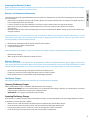
Routine Maintenance
External side brushes: replacing
1. Rotate the cowling.
2. Remove the back wheels.
3. Unscrew the screws xing the ap to the chassis (ref. 1).
4. Replace with new aps.

12
ENGLISH
F
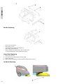
Rear Bin: Replacing
• Remove the back wheels.
• Remove the rear bin.
• Unscrew the two pins xing the ap (ref. 3).
• Grip the ap and pull (ref. 4).
• Replace the ap, insert the two pins in the relative holes.
• Screw up the xing pins and assemble the machine.
Center Brush: Replacing
1. Remove the front bin.
2. Unscrew the screws xing the brush to the shaft.
3. Remove the brush.
4. Replace the brush making sure the orientation of the bristles is correct.
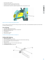
Side Brush: Replacing

13
ENGLISH
• Lift the front of the machine.
• Unscrew the screw (ref. 1), remove the worn brush.
• Install the new brush and x it with the screw (ref. 1).
• Unscrew the two screws (ref. 1), adjust the height of the brush and tighten the screws.
Never use a fuse with a higher amperage than specied.
If a fuse continues to blow, the fault in the wiring, boards (if present) or motors must be Identied and repaired. Have the machine
checked by qualied personnel.
Fuses: Replacing
1. Turn the key switch to the “0” position.
2. Rotate the cowling to access the machine compartment.
3. Remove the fuse holder cover.
4. Check the fuses.
5. Replace with a new fuse.
6. Close the cover again.
Fuse table: For the complete fuse table, see the parts list.
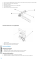
Side Brush Belt: Replacing
1. Rotate the top cowling.
2. Remove the pulley (ref. 2) belt (ref. 1).
3. Unscrew the xing pin (ref. 3) and side arm hooks (ref. 4) from the idle toothed ring.
4. Remove the belt (ref. 1) from the side arm (ref. 4).
5. Replace the belt.
6. Attach the side arm (ref. 4) to the idle toothed wheel again.
7. Screw up the pin (ref. 3).
8. Fit the belt (ref. 1) onto the pulley (ref. 2).

14
ENGLISH
Drive Belt512-712: Replacing
• Rotate the cowling.
• Remove the belt (ref. 1) from the groove of the pulleys.
• Fit the new belt (ref. 1) onto the pulleys.
Regular Maintenance
Daily Operations
1. Empty the bins.
2. Make sure there are no wires or straps rolled around the center brush.
3. Recharge the batteries according to the procedure described.
Weekly Operations
1. Check for wear of the FLAPS. If necessary, replace.
2. Check the condition of the suction air lter and make sure it is undamaged. If necessary, replace.
3. Check the level of battery electrolyte and top up with distilled water if necessary.
Semi-Annual Operations
• Have the electricity circuit checked by qualied personnel.
Table Of Maintenance
• A : On receipt
• B : Every10 hours
• C : Every50 hours
• D : Every100 hours
CHECK A B C D
Center brush: make sure there are no straps or nylon cord
wrapped around the brush. If necessary, remove.
Center brush: check wear of the brush
Side brushes: check wear of the brushes

15
ENGLISH
Flap / Bin gasket: check wear of the aps and gaskets
Dust lter: check that the lter is undamaged and clean
Tires: check that the tires are in good condition and without cuts
at the sides
Battery: check the level of acid in the batteries
General control: check that nuts and screws are tight
Troubleshooting, 512 Ride-On
PROBLEM:
The machine does not function.
CAUSE SOLUTION
Battery disconnected. Connect the battery to the machine.
The battery is at. Recharge the battery.
The key switch is in the 0 position. Turn the key switch to the “1” position.
Emergency button pressed. Release the emergency button.
Main solenoid switch faulty. Replace solenoid switch.
Fuse blown. Replace fuse.
PROBLEM:
Suction motor does not function.
CAUSE SOLUTION
Fuse blown. Replace fuse.
Fan switch on OFF. Press the fan switch.
Suction relay faulty. Replace relay.
Motor malfunction. Replace the motor.
PROBLEM:
The center brush does not turn.
CAUSE SOLUTION
Fuse blown. Replace fuse.
Brush switch not pressed. Press the brush switch.
Suction relay faulty. Replace relay.
Led6 (red) on heavy brush pressure. Reduce the pressure of the center brush on the work surface.
Motor malfunction. Replace the motor.
PROBLEM:
Filter shaker not working.
CAUSE SOLUTION
Fuse blown. Replace fuse.
Filter shaker relay faulty. Replace relay.
Filter shaker switch not pressed. Press the lter shaker switch.
Filter shaker motor faulty. Replace lter shaker motor.

16
ENGLISH
PROBLEM:
Side brush does not turn.
CAUSE SOLUTION
Damaged belt. Replace the belt.
PROBLEM:
The machine raises dust.
CAUSE SOLUTION
Side aps damaged. Replace aps.
Bin full. Empty the bin.
PROBLEM:
Dust comes out of the fan.
CAUSE SOLUTION
Filter incorrectly positioned. Remove the lter and replace correctly.
Worn gaskets. Replace gaskets.
PROBLEM:
Drive motor does not work.
CAUSE SOLUTION
Fuse blown. Replace fuse.
Microswitch under seat not pressed. Sit correctly on the seat.
Drive motor overheated. Turn o the machine and wait for a few minutes.
Heat sensor damaged. Replace heat sensor.
Damaged drive board. Replace drive board.
Motor malfunction. Replace the motor.
Accelerator, potentiometer, malfunction. Replace potentiometer.
Troubleshooting, 512-712
PROBLEM:
The machine does not function.
CAUSE SOLUTION
Battery disconnected. Connect the battery to the machine.
The battery is at. Recharge the battery.
The key switch is in the 0 position. Turn the key switch to the “1” position.
PROBLEM:
Suction motor does not function.
CAUSE SOLUTION
FuseFU4 blown. Replace fuse FU4.
Fan switch on OFF. Press the fan switch.
Motor malfunction. Replace the motor.

17
ENGLISH
PROBLEM:
The center brush does not turn.
CAUSE SOLUTION
Fuse blown. Replace fuse.
Motor malfunction. Replace the motor.
PROBLEM:
Filter shaker not working.
CAUSE SOLUTION
Filter shaker switch not pressed. Press the lter shaker switch.
Filter shaker motor faulty. Replace lter shaker motor.
PROBLEM:
Side brush does not turn.
CAUSE SOLUTION
Damaged belt. Replace the belt.
PROBLEM:
The machine raises dust.
CAUSE SOLUTION
Side aps damaged. Replace aps.
Bin full. Empty the bin.
PROBLEM:
Dust comes out of the fan.
CAUSE SOLUTION
Filter incorrectly positioned. Remove the lter and replace correctly.
Worn gaskets. Replace gaskets.
PROBLEM:
Drive motor does not work.
CAUSE SOLUTION
Fuse blown. Replace fuse.
Motor malfunction. Replace the motor.
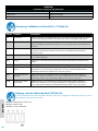
Alarms Displayed, 512 Ride-On
Alarm Problem Description
Acc Accelerator Appears if the accelerator knob (g. A, ref. 9) is activated before the machine is turned on or
after the emergency button has been reset. Release the accelerator knob then action again.
Pot Potentiometer Appears if the speed potentiometer malfunctions or is faulty. The drive has stopped. Release
the knob then action again. If the message continues, the potentiometer could be faulty.
Lim Limitation Appears when a mosfet internal thermal limitation problem occurs. The drive has stopped.
Release the accelerator knob then action again. If the problem continues, wait for a few
minutes.
Hot Overheating When the motor overheat sensor trips, wait for a few minutes for the motor to cool down.
MoS Mosfet Appears when the mosfet is in short circuit. All machine functions are shut down.
bLt Drive block Appears when the battery voltage is too low. Recharge the batteries.

18
ENGLISH
AcS Brush control fault Appears when there is a fault in the relay controlling the brush. Turn o the brush motor
then turn on again. If the message does not disappear, the relay may be disconnected or the
control element on the board may be faulty.
AcA Suction control fault Appears when there is a fault in the relay controlling the suction. Turn o the suction motor
then turn on again. If the message does not disappear, the relay may be disconnected or the
control element on the board may be faulty.
NoFR General solenoid
switch KM1 fault.
Appears when the general solenoid switch is faulty. Turn the machine o then on again.
If the message does not disappear, the solenoid switch may be faulty disconnected or
disconnected, or the control element on the board may be faulty.
Setting The Control Panel Board, 512 RIDE-ON
If the control board is replaced, make sure the dip switches are set according to the type of machine being used.
• SW1 (ON) = 12 V machine power supply
• SW2 (ON) = GEL batteries
• SW3 (ON) = “RIDE-ON” version

19
TEN YEARS UNCONDITIONAL WARRANTY ON ALL POLYETHYLENE ROTATIONAL MOLDED RESERVOIRS TO BE FREE
FROM ALL CRACKS AND/OR CORROSION.
THREE YEARS WARRANTY ON ALL EQUIPMENT PARTS AGAINST DEFECTS IN MATERIAL AND WORKMANSHIP UNDER
NORMAL USE AND CARE WITH THE EXCEPTION OF ANY RUBBER COMPONENTS AND SPRINGS.
ONE YEAR UNCONDITIONAL WARRANTY ON LABOUR AND EQUIPMENT PARTS UNDER NORMAL USE AND CARE
WITH THE EXCEPTION OF ANY RUBBER COMPONENTS AND SPRINGS.
DUSTBANE PRODUCTS LIMITED warrants each new unit of Dustbane Equipment accompanied by this Warranty, including acces-
sories thereto (but except any rubber parts and springs) manufactured or supplied by Dustbane Products Limited and delivered
to the original retail purchaser by an authorised Dustbane distributor, to be free from defects in material and workmanship under
normal use and care. The obligation of Dustbane Products Limited under this Warranty shall be limited to repairing or replacing,
at its option, any part or parts of Dustbane Equipment which shall have been returned to a Dustbane authorised repair depot, and
which, upon examination, shall disclose to the satisfaction of Dustbane Products Limited to have been defective, whereupon any
required repair or replacement shall be made by such Dustbane authorised repair depot.
THE obligation of Dustbane Products Limited to the repair or replacement of defective parts is further limited to :
• to the cost of parts and labour for returns of polyethylene rotational moulded reservoirs made within ten (10) years
• to the cost of parts only for returns made within three (3) years
• the cost of parts and labour for returns made within twelve (12) months based on Dustbane’s Labour Rates all as
calculated from the delivery date of such unit of Dustbane Equipment to the original retail purchaser.
THE provisions of this Warranty shall not apply to:
• any unit of Dustbane Equipment which has been subject to misuse, negligence or accident, or which shall have been
repaired or altered by a person or persons outside a Dustbane authorised repair depot, in any way so as, in the
judgement of Dustbane Products Limited, to a ect adversely its performance and reliability
• normal maintenance services and the replacement of service items (including but not limited to electric cord,
painted parts, any rubber parts and springs, switch and bearings) made in connection with such services as required
in the Dustbane Recommended Maintenance Schedule
NEITHER Dustbane Products Limited nor any authorised Dustbane distributor shall be liable for any claims or damage (including
but not limited to consequential damage and loss of income) resulting from any failure of Dustbane Equipment, whether caused by
negligence or otherwise; Nor for claims or damages resulting from service delays while in performance of the obligations under this
Warranty which are beyond the reasonable control of Dustbane Products Limited or any authorised Dustbane Distributor.
THIS Warranty is expressly in lieu of all other warranties expressed or implied, (including any implied warranty of merchantability
or tness for a particular purpose), and there are no conditions, warranties or representations, whether oral or written except as ex-
pressly stated herein. Neither Dustbane Products Limited, any authorised Dustbane Distributor, any salesman or employees thereof,
nor any other person or individual is authorised to make any statement or representation concerning the obligations of Dustbane
as to the new Equipment unit purchased, nor will Dustbane assume any obligation or liability pursuant to any such statement or
representation except pursuant to this Warranty.
The purchaser upon purchasing any unit of Dustbane Equipment accompanied by this warranty agrees to accept the pro-
tection provided herein and the limitations thereto as being both su cient and commercially reasonable.
1999 Dustbane Products Limited
10
3
1
DUSTBANE WARRANTY
Dustbane Products Ltd. www.dustbane.ca

FRANÇAIS
20
La page est en cours de chargement...
La page est en cours de chargement...
La page est en cours de chargement...
La page est en cours de chargement...
La page est en cours de chargement...
La page est en cours de chargement...
La page est en cours de chargement...
La page est en cours de chargement...
La page est en cours de chargement...
La page est en cours de chargement...
La page est en cours de chargement...
La page est en cours de chargement...
La page est en cours de chargement...
La page est en cours de chargement...
La page est en cours de chargement...
La page est en cours de chargement...
La page est en cours de chargement...
La page est en cours de chargement...
La page est en cours de chargement...
La page est en cours de chargement...
-
 1
1
-
 2
2
-
 3
3
-
 4
4
-
 5
5
-
 6
6
-
 7
7
-
 8
8
-
 9
9
-
 10
10
-
 11
11
-
 12
12
-
 13
13
-
 14
14
-
 15
15
-
 16
16
-
 17
17
-
 18
18
-
 19
19
-
 20
20
-
 21
21
-
 22
22
-
 23
23
-
 24
24
-
 25
25
-
 26
26
-
 27
27
-
 28
28
-
 29
29
-
 30
30
-
 31
31
-
 32
32
-
 33
33
-
 34
34
-
 35
35
-
 36
36
-
 37
37
-
 38
38
-
 39
39
-
 40
40


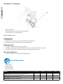
Dustbane Gladiator 512 Operations Manual
- Taper
- Operations Manual
- Ce manuel convient également à
dans d''autres langues
- English: Dustbane Gladiator 512
Documents connexes
-
Dustbane Gladiator 1280 Operations Manual
-
-
-
-
-
-
-
-
-