Kawasaki 691783 Manuel utilisateur
- Catégorie
- Outils électroportatifs
- Taper
- Manuel utilisateur

14 IN. CUT-OFF SAW
INSTRUCTION MANUAL
MANUEL D’UTILISATION POUR
TRONÇONNEUSE DE 14 PO
MANUAL DE INSTRUCCIONES
PARA LA SIERRA
CERCENANTE DE 14 PULGADAS
COMPONENT
COMPOSANT
COMPONENTE
#691783
THIS MANUAL CONTAINS IMPORTANT INFORMATION REGARDING SAFETY, OPERATION, MAINTENANCE AND STORAGE OF THIS
PRODUCT. BEFORE USE, READ CAREFULLY AND UNDERSTAND ALL CAUTIONS, WARNINGS, INSTRUCTIONS AND PRODUCT
LABELS. FAILURE TO DO SO COULD RESULT IN SERIOUS PERSONAL INJURY AND/OR PROPERTY DAMAGE.
CE MANUEL CONTIENT DES INFORMATIONS IMPORTANTES CONCERNANT LA SÉCURITÉ, LE FONCTIONNEMENT ET LE
REMISAGE DE CE PRODUIT. LIRE, ÉTUDIER ET VEILLER À BIEN COMPRENDRE TOUTES LES MISES EN GARDE ET INSTRUCTIONS
ET AUTOCOLLANTS APPOSÉS SUR LE PRODUIT AVANT DE L’UTILISER. NE PAS RESPECTER CES INSTRUCTIONS POURRAIT
ENTRAÎNER DES BLESSURES ET/OU DES DOMMAGES MATÉRIELS.
ESTE MANUAL CONTIENE INFORMACIÓN IMPORTANTE SOBRE LA SEGURIDAD, OPERACIÓN, MANTENIMIENTO Y ALMACE-
NAMIENTO DE ESTE PRODUCTO. ANTES DE USARLO, LEA Y COMPRENDA TODAS LAS PRECAUCIONES, ADVERTENCIAS,
INSTRUCCIONES Y ETIQUETAS DEL PRODUCTO. DE LO CONTRARIO PODRÍA SUFRIR LESIONES GRAVES O CAUSAR DAÑOS
MATERIALES.
IF YOU SHOULD HAVE ANY QUESTIONS OR EXPERIENCE A PROBLEM WITH YOUR ALLTRADE PRODUCT, DO NOT RETURN THIS
PRODUCT TO THE STORE. PLEASE CALL OUR CUSTOMER SERVICE DEPARTMENT AT 1-800-590-3723. BEFORE YOU CALL,
HAVE THE FOLLOWING INFORMATION AVAILABLE: MODEL No., DATE PURCHASED AND STORE LOCATION. AN ALLTRADE
REPRESENTATIVE CAN RESOLVE YOUR PROBLEM OVER THE PHONE. IF YOU WOULD LIKE TO MAKE A SUGGESTION OR
COMMENT, GIVE US A CALL OR EMAIL US AT: INFO@ALLTRADETOOLS.COM. YOUR FEEDBACK IS VITAL TO US.
POUR TOUTE QUESTION OU EN CAS DE PROBLÈME AVEC LE PRODUIT ALLTRADE, NE PAS LE RETOURNER AU MAGASIN OÙ IL
A ÉTÉ ACHETÉ. APPELER LE SERVICE APRÈS-VENTEAU 1-800-590-3723. AVANT D’APPELER, VEILLER À SE PROCURER LES
INFORMATIONS SUIVANTES : No. DE MODÈLE, DATE DE L’ACHAT ET ADRESSE DU MAGASIN. UN REPRÉSENTANT D’ALLTRADE
PEUT RÉSOUDRE VOTRE PROBLÈME PAR TÉLÉPHONE. POUR TOUT COMMENTAIRE OU SUGGESTION, N’HÉSITEZ PAS À NOUS
APPELER OU NOUS CONTACTER PAR COURRIEL À L’ADRESSE : INFO@ALLTRADETOOLS.COM. VOS COMMENTAIRES NOUS
SONT EXTRÊMEMENT PRÉCIEUX.
SI TIENE DUDAS O SURGEN PROBLEMAS CON SU PRODUCTO ALLTRADE, NO LO DEVUELVA A LA TIENDA LLAME A NUESTRO
DEPARTAMENTO DE SERVICIO AL CLIENTE AL 1-800-590-3723. ANTES DE LLAMAR, TENGA A MANO LA SIGUIENTE
INFORMACIÓN: No. DE MODELO, FECHA DE COMPRA Y DIRECCIÓN DE LA TIENDA. UN REPRESENTANTE DE ALLTRADE PUEDE
RESOLVER SU PROBLEMA POR TELÉFONO. SI DESEA HACER ALGUNA SUGERENCIA O COMENTARIO, LLÁMENOS O ENVÍENOS
UN MENSAJE DE CORREO ELECTRÓNICO A. INFO@ALLTRADETOOLS.COM. SUS COMENTARIOS SON FUNDAMENTALES PARA
NOSOTROS.
FOR CUSTOMER SERVICE
POUR LE SERVICE APRÉS VENTE
OU DU CONSOMMATEUR
PARA EL SERVICIO
PARA EL CONSUMIDOR
1-800-590-3723
Printed in China
Imprimé dans la Chine
Impreso en China
KAWASAKI IS A TRADEMARK LICENSED BY KAWASAKI MOTORS
CORP., U.S.A., WHICH DOES NOT MANUFACTURE OR
DISTRIBUTE THIS PRODUCT. CONSUMER INQUIRES SHOULD BE
DIRECTED TO:
KAWASAKI EST UNE MARQUE DE COMMERCE DE KAWASAKI
MOTORS CORP., U.S.A., QUI NE FABRIQUE PAS ET NE DISTRIBUE
PAS CE PRODUIT THIS PRODUCT. LES QUESTIONS DES CONSOM-
MATEURS DOIVENT ÊTRE ADRESSÉES À :
KAWASAKI ES UNA MARCA REGISTRADA CON LICENCIA DE
KAWASAKI MOTORS CORP., E.U.A., QUE NO FABRICA NI
DISTRIBUYE ESTE PRODUCTO. LAS CONSULTAS DE LOS
CONSUMIDORES DEBEN DIRIGIRSE A:
©COPYRIGHT 2010 ALLTRADE TOOLS, LLC.
1431 VIA PLATA
LONG BEACH, CA 90810-1462 USA
691783 – 14 in. Cut-off Saw, Tronçonneuse de 14 Po, Sierra
Cercenante de 14 pulgadas_Rev. 5/24/10

SECTION FIVE
3 YEAR LIMITED WARRANTY . . . . . . . . . . . . . . . . . . . . . . . . . . . . . . . . 26-29
CONGRATULATIONS!
Thanks for choosing this product. At Alltrade, our aim is to provide you with quality
products at an affordable price, and we want you to be totally satisfied with your
product and our Customer Service. If any help and advice is needed, please
contact us at 1-800-590-3723. Properly cared for, this product will give you many
years of satisfaction.
INTENDED USE
This product is intended for consumer use only. This tool is not designed for pro-
fessional use. The power cord should only be used in approved electrical outlets as
described in this manual.
RECOGNIZE SAFETY SYMBOLS, WORDS AND LABELS
READ AND UNDERSTAND ALL INSTRUCTIONS. Failure to
follow all instructions in this manual may result severe personal injury or death.
Keep this manual and refer to it for Safety Instructions, Operating Procedures
and Warranty.
The safety instructions provided in this manual are not intended to cover all possible
conditions and practices that may occur when operating, maintaining and cleaning
power equipment.
Always use common sense and pay particular attention to all the DANGER,
WARNING, CAUTION and NOTE statements of this manual.
This is the safety alert symbol. It is used to alert
you to potential personal injury hazards. Obey all
safety messages that follow this symbol to avoid
possible injury or death.
DANGER indicates an imminently hazardous
situation which, if not avoided, will result in death
or serious injury.
WARNING indicates a potentially hazardous
situation which, if not avoided, could result in
death or serious injury.
TABLE OF CONTENTS
CONGRATULATIONS! . . . . . . . . . . . . . . . . . . . . . . . . . . . . . . . . . . . . . . . . . 2
INTENDED USE . . . . . . . . . . . . . . . . . . . . . . . . . . . . . . . . . . . . . . . . . . . . . . 2
SECTION ONE
RECOGNIZE SAFETY SYMBOLS, WORDS AND LABELS . . . . . . . . . . . . 2-8
IMPORTANT SAFEGUARDS . . . . . . . . . . . . . . . . . . . . . . . . . . . . . . 3
WORK AREA . . . . . . . . . . . . . . . . . . . . . . . . . . . . . . . . . . . . . . . . . . 4
ELECTRICAL SAFETY . . . . . . . . . . . . . . . . . . . . . . . . . . . . . . . . . . . 4-5
PERSONAL SAFETY . . . . . . . . . . . . . . . . . . . . . . . . . . . . . . . . . . . . 5
TOOL USE AND CARE . . . . . . . . . . . . . . . . . . . . . . . . . . . . . . . . . . 5-6
GROUNDING INSTRUCTIONS . . . . . . . . . . . . . . . . . . . . . . . . . . . . 7
EXTENSION CORD USAGE . . . . . . . . . . . . . . . . . . . . . . . . . . . . . . . 7-8
SERVICE . . . . . . . . . . . . . . . . . . . . . . . . . . . . . . . . . . . . . . . . . . . . . 8
SECTION TWO
SPECIFIC SAFETY RULES AND/OR SYMBOLS . . . . . . . . . . . . . . . . . . . 8-13
IMPORTANT SAFETY RULES FOR CUT-OFF SAWS . . . . . . . . . . . . 8-12
SYMBOLS . . . . . . . . . . . . . . . . . . . . . . . . . . . . . . . . . . . . . . . . . . . . 13
SECTION THREE
FUNCTIONAL DESCRIPTION . . . . . . . . . . . . . . . . . . . . . . . . . . . . . . . . . 14
ASSEMBLY . . . . . . . . . . . . . . . . . . . . . . . . . . . . . . . . . . . . . . . . . . . . . . 14-19
ADJUSTING THE ABRASIVE CUT-OFF SAW . . . . . . . . . . . . . . . . . . 15
REMOVING AND INSTALLING THE ABRASIVE CUTTING WHEEL . 16-17
ADJUSTING THE WORK VISE . . . . . . . . . . . . . . . . . . . . . . . . . . . . 17-18
USING THE QUICK LOCK LEVER . . . . . . . . . . . . . . . . . . . . . . . . . . 19
OPERATING INSTRUCTIONS FOR THE CUT-OFF SAW . . . . . . . . . . . . . 19-21
USING THE CUT-OFF SAW . . . . . . . . . . . . . . . . . . . . . . . . . . . . . . . 19-21
SETTING THE CUT-OFF WHEEL DEPTH GAUGE. . . . . . . . . . . . . . . 21
SECTION FOUR
MAINTENANCE AND CLEANING . . . . . . . . . . . . . . . . . . . . . . . . . . . . . . 22-23
TROUBLESHOOTING . . . . . . . . . . . . . . . . . . . . . . . . . . . . . . . . . . . . . . . 23-24
ACCESSORIES . . . . . . . . . . . . . . . . . . . . . . . . . . . . . . . . . . . . . . . . . . . 25
SPECIFICATIONS . . . . . . . . . . . . . . . . . . . . . . . . . . . . . . . . . . . . . . . . . . 25
OTHER CONSUMER DO-IT-YOURSELF (DIY) TOOLS . . . . . . . . . . . . . . 26
1 2

WORK AREA
Keep your work area clean and well lit. Cluttered work benches and dark work
areas may cause accidents or injury.
Do not operate power tools in explosive areas, such as in the presence of
flammable liquids, gases or dust. Power tools create sparks which may ignite
the dust or fumes.
Keep bystanders, children and visitors away while operating a power tool.
Distractions can cause you to lose control.
Make workshop kid proof with padlocks, master switches, or by removing
starter keys.
ELECTRICAL SAFETY
This tool is equipped with an electric cord having an equipment-grounding
conductor and a grounding plug. Grounded tools must be plugged into an
outlet properly installed and grounded in accordance with all codes and ordi-
nances. Never remove the grounding prong or modify the plug in any way. Do
not use any adaptor plugs. Check with a qualified electrician if you are in doubt
as to whether the outlet is properly grounded. If the tools should electrically
malfunction or break down, grounding provides a low resistance path to carry
electricity away from the user.
Avoid body contact with grounded surfaces such as pipes, radiators, ranges and
refrigerators. There is an increased risk of electric shock if your body is grounded.
Do not expose power tools to rain or wet conditions. Water entering a power
tool will increase the risk of electric shock.
Do not abuse the cord. Never use the cord to carry the tool or pull the plug
from an outlet. Keep the cord away from heat, oil, sharp edges, or moving
parts. Replace damaged cords immediately. Damaged cords increase the risk
of electric shock.
When operating the tool outside, use an outdoor extension cord marked “W-A” or
“W.”These cords are rated for outdoor use and reduce the risk of electric shock.
3
CAUTION indicates a potentially hazardous
situation which, if not avoided, may result in
minor or moderate injury.
CAUTION used without the safety alert symbol
indicates a potentially hazardous situation which,
if not avoided, may result in property damage.
NOTE provides additional information that is useful
for proper use and maintenance of this tool. If a
NOTE is indicated make sure it is fully understood.
IMPORTANT SAFEGUARDS
People with electronic devices, such as pacemakers, should consult their
physician(s) before using this product. Operation of electrical equipment in
close proximity to a heart pacemaker could cause interference or failure of
the pacemaker.
WARNING: Some dust created by power sanding, sawing, grinding, drilling and
other construction activities contains chemicals known to the State of California
to cause cancer, birth defects or other reproductive harm.
Some examples of these chemicals are:
• Lead from lead-based paints.
• Crystalline silica from bricks and cement and other masonry products,
and arsenic and chromium from chemically-treated lumber.
Your risk from these exposures varies, depending on how often you do this type
of work. To reduce your exposure to these chemicals: work in a well ventilated
area, and work with approved safety equipment, such as dust masks that are
specially designed to filter out microscopic particles.
WARNING: This product contains chemicals known to the State of California
to cause cancer and birth defects or other reproductive harm.
SAVE THESE INSTRUCTIONS FOR
FUTURE REFERENCE.
4

Do not use tool if the power switch does not turn it “ON” or “OFF”. Any tool that can-
not be controlled with the power switch is dangerous and must be replaced.
Disconnect the power cord plug from the power source before making any
adjustments, changing accessories or storing the tool. Such preventive safe-
ty measures reduce the risk of starting the tool accidentally.
Store idle tools out of reach of children and other untrained persons. Tools
are dangerous in the hands of untrained users.
Maintain tools with care. Keep cutting tools sharp and clean. Properly maintained
tools with a sharp cutting edge are less likely to bind and are easier to control.
Never stand on tool. Serious injury could occur if the tool is tipped or if the cut-
ting tool is unintentionally contacted.
Direction of feed. Feed work into a blade or cutter against the direction of rota-
tion of the blade or cutter only.
Never leave tool running unattended. Turn power off. Don’t leave tool until it
comes to a complete stop.
Check damaged parts. Before further use of the tool, a guard or other part that
is damaged should be carefully checked to determine that it will operate prop-
erly and perform its intended function.
Check for misalignment or binding of moving parts, breakage of parts, and
any other condition that may affect the tool’s operation. If damaged, have the
tool serviced before using. Many accidents are caused by poorly maintained
tools.
Use only accessories that are recommended by the manufacturer for your
model. Accessories that may be suitable for one tool may become hazardous
when used on another tool.
6
Use proper extension cord. Make sure the extension cord being used is in good
condition. If there are any cut or nicks (no matter how deep) in the insulation, DO
NOT use that cord. Also, make sure the extension cord is heavy enough to carry
the current needed by the saw (see RECOMMENDED SIZES OF EXTENSION
CORDS). DO NOT use small "around-the-house” lamp extension cords. These
cords can easily overheat and/or catch fire when used with power tools.
PERSONAL SAFETY
Stay alert, watch what you are doing, and use common sense when operat-
ing a power tool. Do not use tool while tired or under the influence of drugs,
alcohol or medication. A moment of inattention while operating power tools
may result in serious personal injury.
Dress properly. Do not wear loose clothing or jewelry. Contain long hair.
Keep your hair, clothing, and gloves away from moving parts. Loose clothes,
jewelry or long hair can be caught in moving parts.
Avoid accidental starting. Be sure switch is off before plugging in. Carrying
tools with your finger on the switch or plugging in tools that have the switch on
invites accidents.
Remove adjusting keys or wrenches before turning the tool “ON”. Form habit of
checking to see that keys and adjusting wrenches are removed from tool before turn-
ing it on. A wrench or a key that is left attached to a rotating part of the tool may result
in personal injury.
Do not overreach. Keep proper footing and balance at all times. Proper foot-
ing and balance enable better control of the tool in unexpected situations.
Use safety equipment. Always wear eye protection. Dust mask, non-skid safe-
ty shoes, hard hat, or hearing protection must be used for appropriate conditions..
TOOL USE AND CARE
Use clamps or other practical ways to secure and support the workpiece to a
stable platform. Holding the work by hand or against your body is unstable and
may lead to loss of control.
Do not force tool. Use the correct tool for your application. The correct tool
will do the job better and safer at the rate for which it is designed.
5

SERVICE
Tool service must be performed only by qualified repair personnel. Service or
maintenance by unqualified personnel may result in a risk of injury.
When servicing a tool, use only identical replacement parts. Follow instructions
in the Maintenance section of this manual. Use of unauthorized parts or failure to
follow Maintenance Instructions may create a risk of electric shock or injury..
.
SPECIFIC SAFETY RULES AND/OR SYMBOLS
IMPORTANT SAFETY RULES FOR CUT-OFF SAWS
Avoid prolonged contact with dust created by the Cut-off Saw. Allowing the
dust to get into your mouth, eyes, or lay on your skin promotes the absorption
of harmful chemicals into your body.
Read and understand all instructions. Failure to follow all instructions listed in
this manual may result in property damage, damage to the tool, or serious per-
sonal injury or even death.
Unpack the Cut-off Saw completely from its carton. Inspect the saw and
accessories and ensure they are free from defects or breakage due to shipping.
GROUNDING INSTRUCTIONS
In the event of a malfunction or breakdown, grounding provides a path of least
resistance for electric current to reduce the risk of electric shock. This tool is
equipped with an electric cord having an equipment-grounding conductor and a
grounding plug. The plug must be plugged into a matching outlet that is properly
installed and grounded in accordance with all local codes and ordinances.
Do not modify the plug provided - if it will not fit the outlet, have the proper outlet
installed by a qualified electrician.
Improper connection of the equipment-grounding conductor can result in a risk of
electric shock. The conductor with insulation having an outer surface that is green
with or without yellow stripes is the equipment-grounding conductor. If repair or
replacement of the electric cord or plug is necessary, do not connect the equipment-
grounding conductor to a live terminal.
Check with a qualified electrician or service personnel if the grounding instructions
are not completely understood, or if in doubt as to whether the tool is properly
grounded.
Use only 3-wire extension cords that have 3-prong grounding plugs and 3-pole
receptacles that accept the tool’s plug.
Repair or replace damaged or worn cord immediately.
This tool is intended for use on a circuit that has an outlet that looks like the one
illustrated in Figure 1. The tool has a grounding plug that looks like the plug illus-
trated in Figure 1. A temporary adapter, which looks like the adapter illustrated in
Figure 1, may be used to connect this plug to a 2-pole receptacle as shown in Figure
1 if a properly grounded outlet is not available. The temporary adapter should be
used only until a properly grounded outlet can be installed by a qualified electrician.
The green-colored rigid ear, lug, and the like, extending from the adapter must be
connected to a permanent ground such as a properly grounded outlet box.
EXTENSION CORD USAGE
Extension cords are not recommended for use with this Cut-off Saw. Extension
cords, if used, must be properly grounded with a 3-prong plug on one and a 3-hole
receptacle on the other. DO NOT use grounding adapters with an extension cord.
Extension cords must be UL listed and use a minimum of 16 A.W.G. wiring.
Extension cords should never exceed 25 feet in length. Extension cords, that are too
long, cause a voltage drop over the extra distance causing the motor to run slower
with the possibility of causing damage to the motor. Using extension cords with
smaller than the recommended wire gauge run the risk of getting too hot, melting,
and/or causing fires. See table, “Extension Cord Specifications”, on page 25.
7
FIGURE 1. CONNECTING THE CUT -OFF SAW TO THE AC OUTLET
UNGROUNDED AC OUTLET
GROUNDED AC OUTLET
GROUNDING ADAPTER
POWER CORD PLUG
POWER CORD PLUG
COVERPLATE
MOUNTING SCREW
GROUNDING PIN
GROUNDING PIN
GROUNDING
RIGID EAR
8

Properly support extra-long or extra-wide workpieces. Workpieces that are
too long or too wide can tip and cause the blade to seize resulting in a sudden
kickback motion resulting in damage to the workpiece and Cut-off Saw as well
as possible severe injury to the operator.
Do not perform any operation freehand. The workpiece must be tight against the
fence to prevent the piece from moving while it is being cut. Keep the area between
the saw and the workpiece free of debris. Clamp the workpiece if necessary.
NEVER reach around the blade.
Turn tool off and wait for saw blade to stop before moving workpiece or
changing settings.
Use only abrasive cutting wheels that are designed for the various speeds of
this Cut-off Saw. The abrasive cutting wheels should have an arbor size 5/8
inch OR SMALLER. Unsuitable cutting wheels can break without warning
throwing fragments outward at high speeds possibly causing severe injuries.
Release lower guard retraction mechanism after each cut and before
moving or removing the workpiece.
Always keep arms, hands, and fingers away from the workpiece while it is
on the table and the Cut-off Saw is turned on. Severe injury could result.
Always clamp the workpiece firmly against the work table. Never attempt
to hold the workpiece by hand. The blade can seize in the workpiece causing it
to spin rapidly. This will cause loss of control of the workpiece resulting in
severe injuries or damage to the workpiece and Cut-off Saw.
DO NOT cut materials that could shatter or grab the blade.
Make sure the blade is loaded correctly. The arrow on the blade should point
in the same direction as the arrow on the upper blade cover. Blade teeth should
point downward.
Reduce the risk of unintentional starting. Ensure the “ON/OFF” switch is set
to the “OFF” position before plugging the power cord into the AC outlet.
Make sure the blade is properly aligned. Unplug the cord and use your hand to
spin the blade. The blade should spin smoothly without making contact with any
other part of the saw. If there is contact, realign the blade before using the saw.
Make sure the blade and blade guards are free from debris.
Make sure the blade guards are properly installed.
10
Do not operate this Cut-off Saw until it is completely assembled according to
the instructions in this manual. Failure to adhere to these instructions could
result in serious and/or permanent injury to the operator.
Make sure approved eye protection is being worn and properly adjusted and
secured at all times the Cut-off Saw is in use. Everyday eyeglasses only have
impact-resistant lenses and ARE NOT safety glasses. Safety glasses must
conform to ANSI Z87.1 requirements. Approved safety glasses and goggles will
have Z87 printed or stamped on them. Also use face or dust mask if cutting
operation is dusty.
Follow all wiring codes. Use only properly grounded three-hole grounded
receptacles. DO NOT cut the third prong off the power cord. When using an
extension cord, use only UL Listed extension cords with minimum 16 AWG
wiring and a maximum length of 25 feet.
Keep bystanders, children, and visitors at a safe distance from the Cut-off
Saw while it is in operation. Distractions can cause inadvertent misuse
resulting in possible injury to the bystanders or to the operator.
Wear proper apparel. Do not wear loose clothing, gloves, neckties, rings,
bracelets, or other apparel that could possibly become caught in the moving
parts of the Cut-off Saw. When working in a shop environment around power
tools, wear nonslip footwear. Use protective hair covering to contain long hair.
Keep the work area clean at all times. Cluttered areas around the Cut-off Saw
can cause unexpected accidents if the debris comes in contact with the moving
parts of the Cut-off Saw.
Don’t use in dangerous environment. Maintain a proper work environment.
Do not operate the Cut-off Saw in damp or wet locations or expose it to rain.
Water can cause the electrical components to malfunction resulting in damage
to the Cut-off Saw and/or serious injury or death to the operator.
Don’t force the tool. The Cut-off Saw will do a better job and be safer if cutting
operations are performed at the proper speeds as expressed in this manual.
Wear all necessary protective gear, including goggles, ear plugs and a dust
mask.
Keep hands out of the path of the saw blade.
DO NOT operate saw without guards in place.
Do not stand directly in front of the Cut-off Saw. Loose fragments could fly off
at high speeds possibly causing injury.
9

After finishing a cut, release the trigger switch and allow the blade to come
to a complete stop before raising the handle.
Make sure the blade is up to speed before lowering it into the workpiece.
Thoroughly clean the Cut-off Saw before changing types of workpieces.
Combining wood and metal dust can result in an explosion or fire. CONSULT
EXPERT ADVICE BEFORE CUTTING IN WORKPIECES MADE OF MAGNESIUM.
The friction generated by the abrasive wheel could cause the magnesium to
ignite resulting in a very intense fire that could cause severe burns to the oper-
ator and/or seriously damage the Cut-off saw.
Magnesium fires cannot be extinguished using fire extinguisher with an “A”,
“B” or “C” rating. Only a class “D” extinguisher (for flammable metals)
should be used. Do not attempt to extinguish a magnesium fire with water or
other liquid. The result will be an explosive reaction that could result in
severe burns or death to the operator.
Do not use the side of the abrasive wheel as a deburring grinder. This will
substantially weaken the wheel causing an unsafe condition. The wheel
could come apart sending fragments in all directions. Failure to adhere to
this warning could result in serious damage to the tool and/or serious injury
or even death to the operator.
Do not alter in any way, shape, or form the upper and lower guards around the
abrasive cutting wheel. These guards are there to protect the operator against
unexpected conditions, such as breaking, of the cutting wheel. Any modifica-
tion of these guards voids the warranties set forth by the manufacturer.
12
Check all screws and fastenings before use. Make sure the blade screw is
tight and secure.
Cut only one piece of material at a time. Leave enough room for the waste
piece to move once it is cut or it may become wedged against the blade and cre-
ate a hazard.
Be extremely careful when cutting pieces that are very large, very small or
oddly shaped. Make sure all oddly shaped pieces are held securely so they can-
not slip or cause kickback. Moulding should be clamped down flat before cutting.
DO NOT let the workpiece sag or bend. If necessary, use tables or sawhorses
to support the piece while cutting.
NEVER let your fingers get closer than 4 inches to the blade. You cannot cut
any workpiece that requires you to get your hand closer than 4 inches to the
blade.
NEVER allow bystanders behind the saw or close enough to the workpiece to
be hit by flying debris.
Round material such as dowel rods or tubing may roll when cut. Clamp
securely before cutting.
Check that the workpiece is free of nails or other foreign objects.
Make sure ventilation slots are clear of dust or debris.
Mount the saw to a work bench or table before use to prevent unexpected
saw movement. If the saw moves during use, it could cause injury to the oper-
ator and/or damage to the workpiece.
NEVER lubricate the blade while it is in motion.
Before moving the saw, make sure the cord is unplugged and the handle is
locked in the down position. To avoid back injury, do not attempt to lift the saw
by yourself.
Give the saw a test run before cutting. If the tool vibrates excessively or makes
unusual noises, stop operating the saw immediately and correct the problem.
Never hold or clamp the waste portion of the material. Cutoff pieces must be
free to move aside or they may wedge against the blade and cause injury to the
operator or damage to the workpiece.
If the blade becomes clogged with debris, release the trigger switch and let
the blade come to a complete stop before unplugging the tool and removing
the debris.
11

SYMBOLS
IMPORTANT: Some of the following symbols may be used on your tool. Please
study them and learn their meaning. Proper interpretation of these symbols will
allow you to operate the tool better and safer.
SYMBOL NAME EXPLANATION
V Volts Voltage (Potential)
A Amperes Current
L Liters Volume
Kg Kilograms Weight
Alternating Current Type of Current
or d.c. Direct Current Type of Current
or a.c. Alternating or Direct Current Type of Current
Earthing Terminal Grounding Terminal
Class II Construction Denotes Double Insulation
h Hours Time
min Minutes Time
s Seconds Time
Diameter Size of Drill Bits,
Grinding Wheels, etc.
No load speed No-load Rotational Speed
.../min Revolutions per Minute Revolutions, Surface Speed,
Strokes, etc. per Minute
psi Pounds per square inch Pressure
1,2,3, … Ring Selector Settings Speed, Torque or Position Setting
FUNCTIONAL DESCRIPTION
CONTROLS AND COMPONENTS:
1. Trigger Switch
2. Safety Button
3. Arbor Lock Lever
4. Arm Stop
5. Arm Release Knob
6. Abrasive Wheel
7. Lower Guard
8. Motor Brushes
9. Upper Guard
10. Base
ASSEMBLY
DO NOT connect the Cut-off saw to the AC power source until
the receptacle is properly grounded. It is not recommended that an extension cord
be used, but if one is necessary, follow the instructions below.
1413
7
8
6
16
13
14
15
9
10
17
11
11. Rear Spark Shield
12. Depth Cutting Adjustment Screw
13. Fence
14. Adjustable Vise
15. Quick Release Lever
16. Adjustable Vise Handle
17. Grounded Power Cord
18. Wheel Wrench Holder
ACCESSORIES:
19. Wheel Wrench
12
2
1
3
4
5
19
18

REMOVING AND INSTALLING THE ABRASIVE CUTTING WHEEL
To avoid any accidental starting of the cut-off saw,
unplug the saw from the AC power source.
1. Pull out the arm release knob to unlock the saw arm and raise the arm to its
full open position. Then raise and rest the lower guard at its highest position.
2. Push in the arbor shaft lock lever and rotate the abrasive wheel until the arbor
lock engages locking the wheel in place.
3. Hold the arbor shaft lock in place and use the wheel wrench (provided), remove
the arbor hex head screw by turning it counterclockwise. Also, remove the
washer, outer flange and abrasive wheel.
4. Mount the new abrasive wheel securely over the oblong arbor.
15
The 14 in. Cut-off saw comes pre-assembled from the factory and needs no assembly.
TOOLS REQUIRED FOR ASSEMBLY
The tools are supplied by the customer.
It is highly recommended that the 14 in. Cut-off saw be securely mounted to a tool
stand. This is to prevent excessive vibration during use. Mount the Cut-off saw to
the tool stand by:
1. Most tool stands have pre-drilled holes to accommodate a variety of tools.
2. If the tool stand does not have an exact match for the holes, try to align the tool
base with as many pre-drilled holes as possible. Mark and drill new holes for
mounts that have missing holes.
3. Remove the rubber feet screws. Insert three 1/4 in. X 20 screws and washers
through the underside of the tool stand and up through the rubber feet on the
base of the Cut-off saw. The length of the screws should be 1 in. (25mm).
4. Tighten the screws securely.
ADJUSTING THE ABRASIVE CUT-OFF SAW
Disconnect the abrasive Cut-off saw from the AC power
source eliminating any accidental starting of the motor.
16
FIGURE 3. REMOVING/INSTALLING THE CUTTING WHEEL
FIGURE 2. UNLOCKING THE CUT-OFF SAW
ARM RELEASE/LOCK
KNOB
TO CARRY THE CUT-OFF SAW:
Fold down arm to base and push in
the arm release to lock.
TO UNLOCK THE CUT-OFF SAW:
To unlock tool and raise arm,
depress arm slightly and pull out
motor arm release. The motor arm
will pivot upward. See Figure 2.
WASHER
OUTER FLANGE
HEX HEAD
SCREW
LOWER GUARD
ABRASIVE WHEEL
ARBOR SHAFT LOCK LEVER
WRENCH

The angled cut settings on the fence base are only
approximate settings. Always check the accuracy of angled cut settings
using a protractor or bevel gauge.
Adjusting for the width:
1. Using the wheel wrench, turn the two hex head screws counterclockwise and
remove them.
2. Slide the stationary portion of the work vise over the last threaded hole in the
Cut-off Saw base.
3. Install one of the hex head screws into the hole. DO NOT TIGHTEN AT THIS
TIME.
4. Align the second hole of the work vise base with another threaded hole in the
Cut-off base.
5. Install the second hex head screw into the hole. Securely tighten both screws.
5. Align the oblong hole of the inner flange with the oblong arbor and mount the
flange on the arbor and securely against the wheel.
6. Place the hex head screw, washer, outer flange through the threaded arbor
hole and finger tighten.
7. Holding the new abrasive wheel in one hand, use the wheel wrench, turn the
hex head screw clockwise to tighten.
NOTE: Do not overtighten the screw. Overtightening the screw can crack the
wheel.
Do not over tighten the hex head screw. Over tightening the screw can cause
the abrasive wheel to crack resulting in premature failure. This could cause
the abrasive wheel to break and fly off the arbor shaft when the trigger is
engaged. Failure to adhere to this Warning could cause damage to the Cut-
off Saw and severe injury or even death to the operator.
Use only a 14 in. diameter with 1 in. bore abrasive Cut-off wheel rated to a
minimum 4000 RPM. Cut-off wheels that do not match the mounting hard-
ware, exceed a maximum 4200 RPM or fall below the minimum 4000 RPM
may sustain premature wear or breakage and fly off the Cut-off Saw or run
eccentrically resulting in a loss of control. Failure to adhere to this Warning
could cause damage to the Cut-off Saw and severe injury or even death to
the operator.
ADJUSTING THE WORK VISE
The work vise is located on the base of the Cut-off Saw. The vise is made up of two
parts: (1) a stationary fence which can be loosened and rotated from -30° to +45°
degrees and (2) a movable clamp with an adjustable screw handle and a quick-
release lock.
The work vise will also move toward the rear of the base to allow wider workpieces to be
cut. To set up and adjust the work vise, follow the directions below. See Figure 4.
Adjusting for the angle (-30° to +45°):
1. Using the wheel wrench, turn the two fence mounting hex head screws counter-
clockwise to loosen.
2. Rotate the work vise fence to the desired the angle by aligning the gauge on the
vise base with the indicator groove in the Cut-off Saw base. Securely tighten
both screws.
17
18
FIGURE 4. ADJUSTING THE
WORK VISE
SCREWS
STATIONARY FENCE
MOVABLE CLAMP

USING THE QUICK LOCK LEVER
The work vise is equipped with a threaded screw clamp
and handle for tightening the vise. The clamp is also
equipped with a quick lock/release mechanism as stan-
dard equipment. The clamp can be tightened against
the workpiece in the vise by turning the handle clock-
wise and loosened by turning the handle counterclock-
wise. To use the quick lock/release mechanism, follow
the steps below. See Figure 5.
1. Release the tension on the screw clamp by turning
the handle counterclockwise for 1/2 to 1 full turn.
2. Lift the quick lock lever up and pull back the
screw clamp handle sliding the vise open.
3. To tighten, lift the quick lock lever
up and push the screw clamp for-
ward against the workpiece.
4. Push the quick lock lever down into
release mechanism.
5. Turn the screw clamp clockwise to
securely tighten the workpiece in the
vise.
OPERATING INSTRUCTIONS FOR THE CUT-OFF SAW
Do not use the Cut-off saw if the power cord (or exten-
sion cord, if used) is worn, cut, or damaged in any other way. A worn or dam-
aged power cord must be replaced immediately. Contact Alltrade Customer
Service to obtain the proper replacement power cord. Failure to adhere to
this warning could result in damage to the Cut-off saw motor, fire, or severe
electrical shock or even death to the operator.
USING THE CUT-OFF SAW
Disconnect the abrasive Cut-off saw from the AC power
source eliminating any accidental starting of the motor.
Before using the saw, ensure the wheel has cooled down from any previous
actions. Wear approved leather work gloves when handling the various
workpieces and to protect the hands from a hot Cut-off wheel.
FOLLOW THE INSTRUCTIONS BELOW TO OPERATE THE ABRASIVE CUT-OFF
SAW.
1. Adjust the angle of cut. See ADJUSTING THE WORK VISE on pages 17-18.
2. Place the workpiece inside the vise and turn the vise handle clockwise to
securely tighten the workpiece in the vise.
3. Plug the power cord into an approved GROUNDED AC receptacle.
4. Grip the handle and place thumb over the safety button.
5. Press the safety button with thumb. Squeeze the trigger switch. Release the
safety button.
6. Allow the Cut-off saw to spin up to full speed.
7. Slowly pull down on the handle while continuing to squeeze trigger switch.
Lower the Cut-off wheel slowly into the workpiece.
8. Ensure the abrasive Cut-off wheel cuts completely through the workpiece.
Should the Cut-off wheel fail to pass through the workpiece, raise the handle
until it clears. Turn off the Cut-off saw and remove the power cord from the AC
receptacle. Refer to SETTING THE CUT-OFF WHEEL DEPTH GAUGE.
9. Once the cut is completed, turn off the Cut-off saw by releasing the trigger
switch. This also allows the safety button to return to the “OFF” position.
10.Unplug the Cut-off saw from the AC power source. Ensure the abrasive wheel
has stopped spinning before removing the workpiece.
19
FIGURE 6. OPERATING
THE CUT-OFF SAW
TRIGGER SWITCH
SAFETY BUTTON
VISE
20
FIGURE 5. USING THE
QUICK LOCK LEVER
QUICK LOCK/RELEASE
LEVER
WORKPIECE

MAINTENANCE AND CLEANING
Disconnect the abrasive Cut-off saw from the AC power source eliminating
any accidental starting of the motor.
Before using the abrasive Cut-off saw, a thorough inspection should be
made. Check for the following:
1. Loose screws
2. Misalignment or binding of moving parts
3. Cracked or broken parts
4. Damaged electrical wiring
5. Cracked, chipped or bent Cut-off wheel
If any abnormal sounds are heard or abnormal smells or smoke is visible
when Cut-off saw is started, DISCONTINUE USE IMMEDIATELY, TURN OFF
SAW AND REMOVE IT FROM THE AC POWER SOURCE. These could be warn-
ing signs of imminent DANGER. DO NOT USE CUT-OFF SAW IF ANY DAMAGE
IS SUSPECTED. Failure to adhere to this WARNING could result in damage
to the tool or severe injury or death to the operator.
CLEANING
Daily: Using a soft-bristled brush, cloth, or shop vacuum, remove all clippings, dust,
or other debris around the Cut-off saw. Follow the cleaning by using premium light-
weight machine oil and lubricate all movable parts.
DO NOT USE MACHINE OIL ON THE ABRASIVE CUT-OFF
WHEEL. Machine oil will absorb into the abrasive material making up the
wheel and potentially weakening it causing it to break. Should the Cut-off
wheel break while it is in motion, pieces could fly off at high speed damag-
ing the Cut-off saw, the workpiece or resulting in serious injury or even death
to the operator.
MAINTENANCE
The abrasive Cut-off saw is virtually maintenance free. Closed-type, grease-sealed
ball bearings are used throughout the Cut-off saw. These bearings are packed with
grease at the factory and should last the life of the Cut-off saw. The only required
maintenance is covered in the CLEANING Section above. If this particular model
Cut-off saw is equipped with replaceable carbon brushes on the motor, there may
become a time they need replacing. See Figure 8.
11.Use a dry, soft bristle, brush or an air hose and clean any debris remaining
from the cut.
12.Lock down the Cut-off saw with the arm release knob on the side of the cut-off
saw. Store the Cut-off saw in a dry safe location.
SETTING THE CUT-OFF WHEEL DEPTH GAUGE
The cutting depth of the abrasive Cut-off wheel
can be set using the depth cut adjustment
screw. See Figure 7.
1. Using a wrench (not provided),
loosen the jam nut.
2. Adjust the screw counterclockwise to
increase the depth of cut. Tighten the jam
nut.
3. Adjust the jam nut and
turn the screw clockwise
to decrease the depth of
cut. Tighten the jam nut.
For cutting sections of the workpiece completely off,
ensure the depth adjustment screw is set allowing the abrasive Cut-off wheel
to go beyond the base surface into the groove provided.
21
22
FIGURE 7. SETTING THE
DEPTH GAUGE
ADJUSTMENT SCREW
AND JAM NUT

TROUBLE PROBABLE CAUSE SOLUTION
2423
TO REPLACE THE CARBON BRUSHES:
1. Locate the brushes. They should be both sides
of the motor housing at 180˚ degrees apart.
2. Use a slotted blade screwdriver and turn the
brush caps counterclockwise.
3. Remove the caps, tension springs, and carbon
brushes.
4. Place new carbon brushes into the openings.
5. Place the curved end of the brush into opening
first, followed by a tension spring.
6. Insert the cap and, using a slotted blade
screwdriver, tighten the caps by
turning clockwise.
Should the carbon brushes be worn more that 1/2 the original size, replace both
brushes. Ensure the springs operate freely and the tension doesn’t cause armature
of the motor to drag or make noise.
New carbon brushes may arc or spark until they
wear slightly and conform to the armature of the motor. This is a normal
occurrence.
TROUBLESHOOTING
To avoid any accidental starting of the saw during trou-
bleshooting process, unplug the tool from the AC power source.
Should the motor fail to run, for any reason, call Alltrade Customer Service.
Cut-off saw will
not start
1. Tool not plugged in
2. Tripped circuit breaker or
blown fuse
3. Power cord damaged
4. Worn or damaged
carbon brushes
1. Plug in Cut-off saw.
2. Reset circuit breaker or
replace fuse.
3. Have power cord replaced by
authorized service center.
4. Replace carbon brushes.
Cut-off saw
makes
unsatisfactory
cuts
1. Glazed cutting wheel
2. Workpiece incorrectly
clamped in vise
1. Dress the wheel or replace
with a new one.
2. Securely clamp and support
workpiece.
Cut-off wheel
does not come up
to speed
1. Extension cord too light
or too long
2. Low voltage from AC
power source
1. Replace Cord.
2. Consult certified electrical
contractor.
Cut-off saw
vibrates exces-
sively during cut
1. Saw not mounted
securely to workbench
2. Damaged Cut-off wheel
3. Workpiece incorrectly
clamped in vise
1. Tighten all mounting hard-
ware.
2. Replace Cut-off wheel.
3. Clamp workpiece securely in
vise.
Cut-off saw does
not make accurate
cuts
1. Fence improperly adjusted
2. Cut-off wheel not square
to fence
3. Excessive force used to
make cut
4. Workpiece moving
1. Inspect and adjust fence. See
Section on page 17-18.
2. Inspect and adjust wheel.
3. Reduce pressure on cuts - let
wheel do cutting.
4. Clamp workpiece securely in vise.
Material moves
during cutting
1. Fence slipping or work-
piece incorrectly clamped
2. Vise not securely clamp-
ing workpiece
3. Excessive force used to
make cut
1. Tighten fence. See Section on
page 17-18.
2. Clamp workpiece securely in
vise.
3. Reduce pressure on cuts - let
wheel do cutting.
FIGURE 8. REPLACING
CARBON BRUSHES
BRUSHES

OTHER CONSUMER DO-IT-YOURSELF (DIY) TOOLS
Alltrade offers a full range of Kawasaki tools that make DIY jobs easy. If you would
like further information on the following products, please contact Alltrade Customer
Service Department at 1-800-590-3723.
Cordless Drills/Screwdrivers
Impact Wrenches
Sanders
Jigsaws
Circular Saws
Angle Grinders
Reciprocating Saws
Routers
Rotary Tools
Corded and Cordless Multi-Purpose Tools
Wide Range of Accessories and more
3 YEAR LIMITED WARRANTY
Express and Exclusive Limited Warranty to Original Retail Buyer
Alltrade Tools LLC (hereinafter "Alltrade") expressly warrants to the original retail
purchaser of the accompanying KAWASAKI power tool and no one else all parts of
the product (except those parts referred to below which are specifically excluded
from such warranty (see Exclusions)) to be free from defects in materials and work-
manship for a period of three years from original date of purchase, except that such
warranty with regard to the battery shall be for a period of two years from original
date of purchase, unless the tool is used for commercial or rental
purposes.
SPECIAL WARRANTY NOTE FOR COMMERCIAL OR RENTAL USE: The above
warranty for this Kawasaki power tool, including the battery, shall be effective for
only 90 days from the original date of purchase if this tool is used for any
COMMERCIAL OR RENTAL PURPOSE.
The date of purchase shall be the date of shipment to the original purchaser, or the
date the original purchaser took possession, custody or control of the product,
whichever occurred first. This warranty shall be null and void if the product or any
component thereof is modified or altered. This warranty does not apply to any
other product and/or component thereof manufactured or distributed by Alltrade,
ACCESSORIES
Optional accessories for the Cut-off saw can include wire-brush wheels that can be
used for cleaning and layered cloth wheels that can be used for polishing and buff-
ing. Contact ALLTRADE Customer Service at 1-800-590-3723 (toll free) to find out
what accessories are available for the Cut-off saw.
Only use accessories that are designed to fit your partic-
ular Cut-off saw. These accessories should be specifically labeled to match the
speed and arbor size of the grinder. Failure to use the proper accessories could
result in property damage, damage to the grinder, and serious personal injury
to the operator.
Always attach grounded (3-prong) extension cords to grounded (3-hole) outlets.
If the Cut-off saw must be used outside, use an extension cord labeled “W-A” or
“W.” These extension cords are rated for outdoor use and reduce the chances of
electrical shock.
If you must use an extension cord, be sure that the gauge is large enough to carry
the amount of current necessary for your power tool. If not, your tool may experi-
ence a loss of power, excessive voltage drop or overheating. The smaller the gauge
number, the heavier the cord (see table below).
RECOMMENDED SIZES OF EXTENSION CORDS 120 VOLT AC 60 HZ TOOLS
CURRENT RATING IN AMPS CONDUCTOR SIZE IN A.W.G.
MORE THAN NOT MORE THAN 25 FT. 50 FT. 100 FT. 150 FT.
0 6 18 16 16 14
61018161412
10 12 16 16 14 12
12 16 14 12 NOT RECOMMENDED
SPECIFICATIONS
SPECIFICATIONS
Voltage 120V 60 Hz
Rated Current 15.0A
No Load Speed 2800 RPM
Wheel 14 in. X 1/8 in. X 1 in. Bore
Saw Arbor Diameter 7/8 in.
Max Capacity (Round) 5 in.
Max Capacity (Square) 5 in. X 6 in.
25 26

conditions, misapplication, misuse, abuse, accidents, operation at other than
recommended pressures or temperatures, improper storage or freight damage.
Parts damaged or worn by operation in dusty environments are not warranted.
Failure to follow recommended operating and maintenance procedures also
voids warranty.
This limited warranty does not apply to accessory items such as drill bits,
screwdriving bits, circular saw blades, jigsaw blades, grinding wheels, sanding
sheets and other related items.
DAMAGE TO THE PRODUCT RESULTING FROM TAMPERING, ACCIDENT, ABUSE,
NEGLIGENCE, FAILURE TO FOLLOW INSTRUCTIONS, UNAUTHORIZED REPAIRS
OR ALTERATIONS, DAMAGE WHILE IN TRANSIT TO OUR SERVICE FACILITY,
USE OF UNAPPROVED OR IMPROPER ATTACHMENTS OR ACCESSORIES,
COMMERCIAL AND RENTAL APPLICATIONS OR OTHER CAUSES UNRELATED TO
PROBLEMS WITH MATERIAL OR WORKMANSHIP ARE NOT COVERED BY THIS
WARRANTY.
Alltrade will not be liable for the following: labor charges, loss or damage resulting
from improper operation, maintenance or repairs made by other persons;
pre-delivery services such as assembly, oil or lubricants, and adjustment;
maintenance services that are normally required to maintain the product.
The use of other than genuine Alltrade Repair Parts will void warranty.
Warranty Disclaimers
EXCLUSION AND DISCLAIMER OF ALL OTHER EXPRESS WARRANTIES,
GUARANTIES AND/OR REPRESENTATIONS. EXCEPT FOR THE LIMITED WARRANTY
PROVIDED ABOVE, ALL OTHER EXPRESS WARRANTIES, GUARANTIES AND/OR
REPRESENTATIONS BY ALLTRADE AND/OR ITS REPRESENTATIVE(S) REGARDING
THE DESIGN, MANUFACTURE, PURCHASE, USE AND/OR OPERATION OF THE
PRODUCT OR ANY COMPONENT THEREOF SOLD HEREUNDER, REGARDLESS OF
WHETHER ANY SUCH WARRANTY, GUARANTY AND/OR REPRESENTATION,
WRITTEN OR ORAL, ARISES BY OPERATION OF LAW AND/OR EQUITY AND/OR BY
ANY ACT OR OMISSION OF ALLTRADE AND/OR ITS REPRESENTATIVE(S), OR THE
BUYER, ARE HEREBY EXPRESSLY EXCLUDED AND DISCLAIMED BY ALLTRADE
AND/OR ITS REPRESENTATIVES. PURCHASER KNOWINGLY AND WILLINGLY
WAIVES ANY AND ALL SUCH WARRANTIES AND RIGHTS, CLAIMS AND/OR
CAUSES OF ACTION ARISING THEREFROM OR BASED THEREON. PURCHASER’S
SOLE AND EXCLUSIVE REMEDY IS AS STATED ABOVE.
EXCLUSION AND DISCLAIMER OF ALL IMPLIED WARRANTIES, INCLUDING THE
IMPLIED WARRANTIES OF MERCHANTABILITY AND FITNESS FOR A PARTICULAR
PURPOSE. NO WARRANTY, ORAL OR WRITTEN, OTHER THAN THE ABOVE
27
and does not apply to products and/or components thereof designed, manufactured
and/or assembled by others, for which Alltrade makes no warranties whatsoever.
THERE ARE NO WARRANTIES WHICH EXTEND BEYOND THE DESCRIPTION ON
THE FACE HEREOF.
Warranty Performance
By purchasing the product, purchaser expressly acknowledges and agrees that their
sole and exclusive remedy under this warranty shall be strictly limited to the repair
or replacement of any covered nonconforming items or parts thereof provided that
any such nonconforming item and/or part is promptly returned to Alltrade’s facility
postage pre-paid and insured (address: ALLTRADE Warranty Claims & Repair,
1431 Via Plata, Long Beach, CA 90810, Attn: Customer Service #1-800-590-3723)
within the applicable warranty period, with a written request by purchaser that
Alltrade repair and/or replace the nonconforming item and/or part. We recommend
that you keep the original product packaging in the event you need to ship the unit.
We suggest the package be insured against loss or in transit damage. When
sending your product include your name, address, phone number, dated proof
of purchase (or copy), and a statement about the nature of problem. Warranty
coverage is conditioned upon purchaser furnishing Alltrade with adequate written
proof that they are the original purchaser and of the original purchase date. Parts
returned, freight prepaid and insured, to Alltrade’s facility (see above address) will
be inspected and, at Alltrade’s option, repaired and/or replaced free of charge if
found to be defective and subject to warranty. Alltrade retains the sole discretion
to determine whether any item or part is nonconforming and, if so, whether the
item and/or part will be repaired and/or replaced. If the unit is repaired, new or
reconditioned replacement parts may be used. If Alltrade chooses to replace
the product, it may replace it with a new or reconditioned one of the same or
comparable design. The repaired or replaced unit will be warranted under the terms
of the remainder of the warranty period. Typically, a defective product that is
returned within the first 30 days after the purchase date will be replaced; for items
returned after the first 30 days and within the warranty period, covered defective
parts not subject to normal wear and tear or other exclusions will be repaired or
replaced, at Alltrade’s option. During the warranty period, Alltrade will be responsi-
ble for the return shipping charges. Alltrade’s repair and/or replacement of any non-
conforming item and/or part thereof shall constitute fulfillment of all
obligations to the purchaser. Alltrade shall not be responsible or liable for any
expense, including freight charges, or repairs made outside Alltrade’s facility, unless
expressly agreed to by Alltrade in writing. Under no circumstances shall Alltrade
bear any responsibility for loss of the unit, loss of time or rental, inconvenience,
commercial loss or consequential damages.
Exclusions
This warranty does not cover parts damaged due to normal wear, abnormal
28

3029
WARRANTY IS MADE WITH REGARD TO THIS PRODUCT. ALL EXPRESS AND/OR
IMPLIED WARRANTIES, GUARANTIES AND/OR REPRESENTATIONS BY ALLTRADE
AND/OR ITS REPRESENTATIVE(S) REGARDING THE DESIGN, MANUFACTURE,
PURCHASE, USE AND/OR OPERATION OF THE PRODUCT OR ANY COMPONENT
THEREOF SOLD HEREUNDER, REGARDLESS OF WHETHER ANY SUCH WARRANTY,
GUARANTY AND/OR REPRESENTATION, WRITTEN OR ORAL, ARISES BY
OPERATION OF LAW AND/OR EQUITY AND/OR BY ANY ACT OR OMISSION OF
ALLTRADE AND/OR ITS REPRESENTATIVE(S), OR THE PURCHASER, INCLUDING
BUT NOT LIMITED TO THE IMPLIED WARRANTY OF MERCHANTABILITY AND THE
WARRANTY OF FITNESS FOR A PARTICULAR PURPOSE, ARE HEREBY EXPRESSLY
EXCLUDED AND DISCLAIMED BY ALLTRADE AND/OR ITS REPRESENTATIVES.
PURCHASER KNOWINGLY AND WILLINGLY WAIVES ANY AND ALL SUCH
WARRANTIES AND RIGHTS, CLAIMS AND/OR CAUSES OF ACTION ARISING
THEREFROM OR BASED THEREON. PURCHASER’S SOLE AND EXCLUSIVE
REMEDY IS AS STATED ABOVE.
Limitation Of Liability
IN NO EVENT SHALL ALLTRADE AND/OR ITS REPRESENTATIVE(S) BE LIABLE FOR
INDIRECT, INCIDENTAL, SPECIAL AND/OR CONSEQUENTIAL DAMAGES OF ANY
KIND ARISING OUT OF OR RELATED TO, DIRECTLY OR INDIRECTLY, ANY BREACH
OF ANY PROVISION OF ANY AGREEMENT BETWEEN ALLTRADE AND/OR ITS
REPRESENTATIVE(S) AND PURCHASER, ANY WARRANTY HEREUNDER,
AND/OR THE EXISTENCE, DESIGN, MANUFACTURE, PURCHASE, USE AND/OR
OPERATION OF ANY ITEM(S) SOLD HEREUNDER EVEN IF ALLTRADE AND/OR ITS
REPRESENTATIVE(S) HAS BEEN ADVISED OF THE POSSIBILITY OF ANY SUCH
DAMAGES. IN NO EVENT, WHETHER AS A RESULT OF A BREACH OF CONTRACT,
WARRANTY, TORT (INCLUDING NEGLIGENCE) OR OTHERWISE, SHALL
ALLTRADE’S AND/OR ITS REPRESENTATIVE(S)’ LIABILITY EXCEED THE PRICE OF
THE PRODUCT. ANY AND ALL LIABILITY CONNECTED WITH THE USE OF
THIS PRODUCT SHALL TERMINATE UPON THE EXPIRATION OF THE WARRANTY
PERIODS SPECIFIED ABOVE.
Limitations on Warranty Disclaimers
Some states do not allow limitations on how long an implied warranty lasts
and some states do not allow the exclusion or limitation of the incidental or
consequential damages, so part or all of the above limitations or exclusions may not
apply to you. This warranty gives you specific legal rights, and you may also have
other rights which vary from state to state.
If your product is not covered by this warranty, please call our Customer Service
Department toll free at 1-800-590-3723 for general repair information and charges.

AUTRES OUTILS POUR LE BRICOLAGE . . . . . . . . . . . . . . . . . . . . . . . . 57
SECTION CINQ
GARANTIE LIMITÉE DE 3 ANS . . . . . . . . . . . . . . . . . . . . . . . . . . . . . . . 57-60
FÉLICITATIONS !
Merci d’avoir choisi ce produit. L’objectif d’Alltrade est de vous fournir des produits
de qualité à un prix raisonnable et de vous donner entière satisfaction avec nos
outils et notre service après-vente, Pour obtenir de l’aide et des conseils, ne pas
hésiter à nous contacter au 1-800-590-3723. Correctement entretenu, cet outil
vous donnera des années de satisfaction.
USAGE PRÉVU
Cet outil est conçu pour l’usage domestique seulement. Cet outil n’est pas conçu
pour l’usage professionnel. Le cordon d’alimentation ne doit être branché que sur
une prise électrique approuvée, telle que décrite dans ce manuel. Ne pas utiliser les
cordons d’alimentation et/ou prolongateurs appropriés peut causer un incendie et
des dommages à la scie à ruban.
RECONNAISSANCE DES SYMBOLES, TERMES ET AUTOCOLLANTS DE SÉCURITÉ
LIRE ET VEILLER À BIEN COMPRENDRE TOUTES LES
INSTRUCTIONS. Le non-respect de toutes les instructions peut entraîner des
blessures graves ou mortelles.Conserver ce manuel et le consulter pour les
instructions de sécurité, les procédures d’utilisation et la garantie.
Les instructions de sécurité contenues dans ce manuel ne sauraient en aucun cas
couvrir toutes les situations et pratiques d’utilisation, d’entretien et de nettoyage
des outils électriques.
Toujours faire preuve de bon sens et prêter une attention particulière aux textes
intitulés DANGER, AVERTISSEMENT, ATTENTION ou REMARQUE contenus dans ce
manuel.
Ce symbole accompagne les avertissements de sécurité. Il
est conçu pour avertir de risques de blessures. Respecter
toutes les instructions accompagnées de ce symbole pour
éviter des risques de blessures graves ou mortelles.
DANGER Indique une situation extrêmement dangereuse
qui, si elle n’est pas évitée, aura pour conséquences des
blessures graves ou mortelles.
AVERTISSEMENT Indique une situation potentiellement
dangereuse qui, si elle n’est pas évitée, pourrait avoir pour
conséquences des blessures graves ou mortelles.
AVERTISSEMENT
TABLE DES MATIÈRES
FÉLICITATIONS ! . . . . . . . . . . . . . . . . . . . . . . . . . . . . . . . . . . . . . . . . . . . . . 32
USAGE PRÉVU . . . . . . . . . . . . . . . . . . . . . . . . . . . . . . . . . . . . . . . . . . . . . . . 32
SECTION UN
RÈGLES GÉNÉRALES DE SÉCURITÉ – POUR TOUS LES OUTILS . . . . 32-38
RECONNAÎTRE LES SYMBOLES, LES MOTS ET
LES ÉTIQUETTES SUR LA SÉCURITÉ . . . . . . . . . . . . . . . . . . . . . . . 32-33
IMPORTANT : . . . . . . . . . . . . . . . . . . . . . . . . . . . . . . . . . . . . . . . . . 33
LIEU DE TRAVAIL . . . . . . . . . . . . . . . . . . . . . . . . . . . . . . . . . . . . . . 34
SÉCURITÉ ÉLECTRIQUE . . . . . . . . . . . . . . . . . . . . . . . . . . . . . . . . . 34
SÉCURITÉ PERSONNELLE . . . . . . . . . . . . . . . . . . . . . . . . . . . . . . . 35
UTILISATION ET ENTRETIEN DE L’OUTIL . . . . . . . . . . . . . . . . . . . . 35-36
INSTRUCTIONS DE MISE À LA TERRE . . . . . . . . . . . . . . . . . . . . . 36-37
UTILISATION DE RALLONGE . . . . . . . . . . . . . . . . . . . . . . . . . . . . . 37
DÉPANNAGE . . . . . . . . . . . . . . . . . . . . . . . . . . . . . . . . . . . . . . . . . . 38
SECTION DEUX
REGLES DE SECURITE SPECIFIQUES ET/OU AUTRES SYMBOLES . . . . . . . . 38-43
CONSIGNES DE SÉCURITÉ IMPORTANTES CONCERNANT
LES SCIES À ONGLET . . . . . . . . . . . . . . . . . . . . . . . . . . . . . . . . . . 38-43
SYMBOLES . . . . . . . . . . . . . . . . . . . . . . . . . . . . . . . . . . . . . . . . . . . . . . 43
SECTION TROIS
DESCRIPTION FONCTIONNELLE . . . . . . . . . . . . . . . . . . . . . . . . . . . . . . 44
ASSEMBLAGE . . . . . . . . . . . . . . . . . . . . . . . . . . . . . . . . . . . . . . . . . . . . 44-49
RÉGLAGE DE LA TRONÇONNEUSE À DISQUE ABRASIF . . . . . . . . 45
RETRAIT/INSTALLATION DU DISQUE ABRASIF . . . . . . . . . . . . . . . .46-47
RÉGLAGE DE L’ÉTAU DE BLOCAGE . . . . . . . . . . . . . . . . . . . . . . . . 47-48
UTILISATION DU LEVIER DE BLOCAGE RAPIDE . . . . . . . . . . . . . . 49
MODE D’EMPLOI DE LA TRONÇONNEUSE . . . . . . . . . . . . . . . . . . . . . . 49-52
FONCTIONNEMENT DE LA TRONÇONNEUSE À DISQUE ABRASIF 50-51
RÉGLAGE DE LA BUTÉE DE PROFONDEUR DU DISQUE . . . . . . . . 51-52
SECTION QUATRE
ENTRETIEN ET NETTOYAGE . . . . . . . . . . . . . . . . . . . . . . . . . . . . . . . . . 52-53
GUIDE DE DÉPANNAGE . . . . . . . . . . . . . . . . . . . . . . . . . . . . . . . . . . . . 54-55
ACCESSOIRES . . . . . . . . . . . . . . . . . . . . . . . . . . . . . . . . . . . . . . . . . . . 55-56
CARACTÉRISTIQUES . . . . . . . . . . . . . . . . . . . . . . . . . . . . . . . . . . . . . . 56
31

LIEU DE TRAVAIL
Garder le lieu de travail propre et bien éclairé. Les établis encombrés et le
manque de lumière sont propices aux accidents.
Ne pas utiliser d’outils électriques dans une atmosphère explosive, par
exemple en présence de liquides, de gaz ou de poussières inflammables.
Les outils électriques produisent des étincelles risquant d’enflammer les pous-
sières ou vapeurs.
Garder les badauds, enfants et visiteurs à l’écart pendant l’utilisation d’un
outil électrique. Les distractions peuvent causer une perte de contrôle.
SÉCURITÉ ÉLECTRIQUE
Les outils munis d’une connexion à la terre doivent être branchés dans une
prise correctement installée et mise à la terre conformément aux codes et
règlements en vigueur. Ne jamais retirer la broche de terre ou modifier la
fiche d’une quelconque façon. Ne pas utiliser de prises adaptatrices. Faire
vérifier par un électricien qualifié en cas de doute sur l’intégrité de la mise à la
terre de la prise. Si le fonctionnement électrique de l’outil est défectueux ou s’il
tombe en panne, la mise à la terre présente moins de résistance au courant
électrique que l’utilisateur.
Éviter tout contact du corps avec des surfaces mises à la terre, telles que
tuyaux, radiateurs, cuisinières et réfrigérateurs. Le risque de choc électrique
est accru lorsque le corps est mis à la terre.
Ne pas exposer les outils électriques à l’eau ou l’humidité. La pénétration
d’eau dans ces outils accroît le risque de choc électrique.
Ne pas maltraiter le cordon d’alimentation. Ne jamais utiliser le cordon d’ali-
mentation pour transporter l’outil et ne jamais débrancher ce dernier en tirant
sur le cordon. Garder le cordon à l’écart de la chaleur, de l’huile, des objets
tranchants et des pièces en mouvement. Remplacer immédiatement tout cordon
endommagé. Un cordon endommagé accroît le risque de choc électrique.
Utiliser des cordons prolongateurs marqués “W-A” ou “W”. Ces cordons
sont conçus pour l’usage en extérieur et réduisent les risques de choc électrique.
S’assurer que le cordon prolongateur utilisé est en bon état. Si l’isolation présente
des coupures ou entailles (quelle que soit leur profondeur) NE PAS utiliser le cor-
don. En outre, s’assurer que la capacité du cordon est suffisante pour supporter l’in-
tensité nécessaire à la scie (voir EXIGENCES ÉLECTRIQUES). NE PAS utiliser de
petits cordons prolongateurs “ ménagers ”. Ces cordons surchauffent facilement
et/ou s’enflamment lorsqu’ils sont utilisés avec des outils électriques.
AVERTISSEMENT
AVERTISSEMENT
ATTENTION Indique une situation potentiellement
dangereuse qui, si elle n’est pas évitée, pourrait avoir pour
conséquences des blessures légères ou de gravité
modérée.
ATTENTION Indique une situation de danger potentiel qui,
s’il n’est pas évité, peut avoir pour conséquences des
blessures légères ou des dommages matériels.
REMARQUE Une REMARQUE contient des informations
utiles concernant l’utilisation et l’entretien corrects de cet
outil. Veiller à bien comprendre la signification de chaque
REMARQUE.
IMPORTANT :
Les personnes porteuses d’appareils électroniques, tels que stimulateurs
cardiaques doivent consulter leur médecin avant d’utiliser ce produit.
L’utilisation de matériel électrique à proximité d’un stimulateur cardiaque
peut nuire à son fonctionnement ou causer sa défaillance.
AVERTISSEMENT : La poussière dégagée par certains matériaux lors du
ponçage, sciage, meulage, perçage et autres opérations de construction
contient des produits chimiques reconnus causer le cancer, des malformations
congénitales ou des lésions de l’appareil reproducteur.
Voici certains exemples de ces produits chimiques :
• Le plomb contenu dans la peinture au plomb.
• La silice cristalline contenue dans les briques, le ciment et d’autres
produits de maçonnerie et l’arsenic et le chrome contenus dans le bois
de construction traité par produits chimiques.
Le risque présenté par l’exposition à ces produits varie en fonction de la
fréquence de ce type de travail. Pour réduire l’exposition à ces produits
chimiques : travailler dans un endroit bien aéré et utiliser des équipements de
sécurité approuvés tels que masques de protection spécialement conçus pour
filtrer les particules microscopiques.
AVERTISSEMENT : Cet article contient des produits chimiques qui, dans l’é-
tat de Californie, sont connus pour provoquer cancers, malformations con-
génitales ou autres problèmes de reproduction.
REMARQUE
ATTENTION
ATTENTION
33

Débranchez la prise de courant de corde de pouvoir de la source de pouvoir
avant le fait de faire n'importe quels ajustages, accessoires changeants ou
le fait de conserver l'instrument. Ces mesures de sécurité réduisent les
risques de démarrage accidentel de l’outil.
Ranger les outils non utilisés hors de la portée des enfants et des person-
nes n’ayant pas reçu des instructions adéquates. Dans les mains de person-
nes n’ayant pas reçu des instructions adéquates, les outils sont dangereux.
Entretenir soigneusement les outils. Garder les outils bien affûtés et pro-
pres. Des outils correctement entretenus et dont les tranchants sont bien
affûtés risquent moins de se bloquer et sont plus faciles à contrôler.
Vérifier qu’aucun désalignement, blocage, pièce mobile, bris de pièce et
tout autre condition ne puisse entraver le fonctionnement de l’outil. Si l’outil
est endommagé, le faire réparer avant de l’utiliser. Plusieurs accidents sont
causés par des outils mal entretenus.
N’utiliser que des accessoires recommandés par le fabricant de votre mod-
èle. Des accessoires qui peuvent convenir à un outil pourraient créer un risque
de blessures lorsqu’ils sont utilisés sur un autre outil.
DIRECTIVES DE MISE À LA TERRE
En cas de bris ou de défaillance, la mise à la terre offre un trajet de moindre résis-
tance au courant électrique afin de réduire le risque d'électrocution. Cet outil est
équipé d'un cordon d'alimentation électrique doté d'un conducteur de protection et
d'une prise de mise à la terre. La fiche doit être branchée dans une prise de courant
de tension correspondante, convenablement installée et mise à la terre, conformé-
ment à tous les codes et règlements locaux.
Ne modifiez pas la prise fournie; si elle ne correspond pas à la prise de courant,
faites installer la bonne prise de courant par un électricien qualifié.
Un mauvais branchement du conducteur de protection peut entraîner un risque
d'électrocution. Le conducteur ayant un revêtement isolant vert, avec ou sans
rayures jaunes, est le conducteur de protection. Si une réparation ou le remplace-
ment du cordon d'alimentation électrique ou de la fiche s'avère nécessaire, ne
branchez pas le conducteur de protection à une borne sous tension.
Vérifiez auprès d'un électricien qualifié ou un technicien en entretien et réparation
si vous ne comprenez pas tout à fait les directives de mise à la terre ou si vous ne
savez pas si l'outil est bien mis à la terre.
N'utilisez que des rallonges trilifiques dotées de prises de mise à la terre à trois
broches et des prises tripolaires compatibles avec la fiche de l'outil.
ATTENTION
SÉCURITÉ PERSONNELLE
Rester vigilant. prêter attention au travail et faire preuve de bon sens lors de
l’utilisation de tout outil électrique. Ne pas utiliser cet outil en état de fatigue ou
sous l’influence d’alcool, de drogues ou de médicaments. Un moment d’inatten-
tion pendant l’utilisation d’un outil électrique peut entraîner des blessures graves.
Porter une tenue appropriée. Ne porter ni vêtements amples, ni bijoux.
Retenir les cheveux longs. Garder les cheveux longs, les vêtements et les
gants à l’écart des piècesen mouvement. Les vêtements amples, bijoux et
cheveux longs peuvent se prendre dans les pièces en mouvement.
Éviter les démarrages accidentels. S’assurer que le commutateur est en
position d’arrêt avant de brancher l’outil. Le transport d’un outil avec le doigt
sur la gâchette ou le branchement d’un outil dont le commutateur est en posi-
tion de marche peut causer un accident.
Retirer les outils et clés de réglages avant de mettre l’outil en marche. Un
outil ou une clé laissée sur une pièce rotative de l’outil peut causer des
blessures.
Ne pas travailler hors de portée. Toujours se tenir bien campé et en équili-
bre. Une bonne tenue et un bon équilibre permettent de mieux contrôler l’outil
en cas de situation imprévue.
Utiliser l’équipement de sécurité. Toujours porter une protection oculaire.
Suivant les conditions, porter des chaussures de sécurité antidérapantes, un
casque ou une protection auditive.
UTILISATION ET ENTRETIEN DE L’OUTIL
Dans la mesure du possible, utiliser des serre-joint (non inclus) pour main-
tenir la pièce sur une surface stable. Une pièce tenue à la main ou contre son
corps est instable et peut causer une perte de contrôle.
Ne pas forcer l’outil. Utiliser un outil approprié pour le travail. Un outil
approprié exécutera le travail mieux et de façon moins dangereuse s’il fonc-
tionne dans les limites prévues.
Ne pas utiliser l’outil si le commutateur ne permet pas de le mettre en
marche ou de l’arrêter. Tout outil qui ne peut pas être contrôlé par son com-
mutateur est dangereux et doit être réparé ou remplacé.
ATTENTION
AVERTISSEMENT
3635

DÉPANNAGE
La réparation de l’outil doit être effectuée uniquement par du personnel de serv-
ice qualifié. La réparation ou l’entretien effectués par du personnel non qualifié
peut entraîner un risque de blessures.
Lors de la réparation d’un outil, n’utiliser que des pièces de rechange iden-
tiques. Suivre les instructions de la section Entretien de ce manuel. L’usage de
pièces non autorisées ou le non respect des instructions d’entretien peut présenter
des risques dechoc électrique ou de blessures.
RÈGLES ET/OU SYMBOLES DE SÉCURITÉ PARTICULIERS
RÈGLES DE SÉCURITÉ IMPORTANTES CONCERNANT LES SCIES À ONGLET
Évitez tout contact prolongé avec la poussière produite par la tronçonneuse.
Laisser la poussière entrer dans votre bouche, vos yeux ou se déposer sur
votre peau favorise l'absorption par votre corps de produits chimiques dom-
mageables.
Lisez et assurez-vous de bien comprendre toutes les directives. Toute omis-
sion de suivre l'ensemble des directives indiquées dans le présent mode d'em-
ploi peut entraîner des dommages, des dommages à l'outil ou des blessures
graves voire un décès.
Sortez la tronçonneuse complètement de sa boîte. Inspectez la scie et les
accessoires et assurez-vous qu'ils ne comportent aucun bris ou défectuosité
causé par le transport.
N'utilisez pas cette tronçonneuse avant d'avoir fini de l'assembler confor-
mément aux directives du présent mode d'emploi. Ne pas observer ces direc-
tives pourrait entraîner des blessures graves et/ou permanentes à l'utilisateur.
Assurez-vous de porter les lunettes de protection approuvées et qu'elles
sont bien attachées et ajustées en tout temps lorsque vous employez la
tronçonneuse. Les lunettes ordinaires ne sont équipées que de lentilles résis-
tantes aux chocs et NE SONT PAS des lunettes de protection. Les lunettes de
protection que vous portez doivent être conformes aux exigences de la norme
ANSI Z87.1. Les lunettes et les lunettes à coques étanches portent une éti-
quette ou une étampe sur laquelle on peut lire « Z87 ».
AVERTISSEMENT
Réparez ou remplacez immédiatement un cordon d'alimentation endommagé ou
usé.
Cet outil est conçu pour être utilisé sur un circuit qui a une prise de courant sem-
blable à celle de l'illustration de la Figure 1. L'outil a une prise de mise à la terre
semblable à la fiche illustrée dans la Figure 1. Un adaptateur temporaire, comme
celui de l'illustration de la Figure 1, peut être utilisé pour brancher ce genre de fiche
à une prise de courant bipolaire, comme l'illustre la Figure 1, si une prise de courant
convenablement mise à la terre n'est pas disponible. L'adaptateur temporaire ne
devrait être utilisé que jusqu'à ce qu'une prise de courant convenablement mise à
la terre puisse être installée par un électricien qualifié.
Le dispositif de mise à la terre (oreille, patte rigide, etc.) de couleur verte dont est
doté l'adaptateur doit être branché à une prise de mise à la terre permanente
comme une boîte de sortie électrique convenablement mise à la terre.
UTILISATION D'UNE RALLONGE
L'utilisation de rallonges n'est pas recommandée avec cette tronçonneuse. S'il faut
en utiliser une, employez toujours une rallonge convenablement mise à la terre (à
trois broches) et branchez-la dans une prise de courant triphasée (à trois trous).
N'UTILISEZ PAS d'adaptateurs de mise à la terre avec une rallonge. Les ral-
longes doivent porter la marque « UL listed » et avoir un calibre américain normal-
isé minimum de 16. Une rallonge électrique ne devrait jamais mesurer plus de 7,6
m (25 pi). Dans le cas contraire, la tension baisse dans la section supplémentaire,
ralentissant ainsi le moteur, ce qui peut l'endommager. L’utilisation d’une rallonge
électrique de calibre insuffisant peut provoquer sa surchauffe ou sa fonte, voire un
incendie. Voir le tableau intitulé « Spécifications concernant les rallonges », à la
page 56.ENTRETIEN ET RÉPARATION
37
FIGURE 1.
BRANCHEMENT DE TRONÇONNEUSE
DANS LA PRISE ÉLECTRIQUE C.A
PRISE DE COURANT ALTERNATIF NON MISE À LA TERRE
PRISE DE COURANT ALTERNATIF
MISE À LA TERRE
ADAPTATEUR DE MISE À LA TERRE
POUR PRISE DE COURANT ALTERNATIF
MISE À LA TERRE
FICHE DE CORDON
D'ALIMENTATION
FICHE DE CORDON
D'ALIMENTATION
VIS DE FIXATION DE LA
PLAQUE DE PROTECTION
BROCHE DE
MISE À LA
TERRE
BROCHE DE MISE
À LA TERRE
ADAPTATEUR DE
FICHE MISE À LA
TERRE
38
La page est en cours de chargement...
La page est en cours de chargement...
La page est en cours de chargement...
La page est en cours de chargement...
La page est en cours de chargement...
La page est en cours de chargement...
La page est en cours de chargement...
La page est en cours de chargement...
La page est en cours de chargement...
La page est en cours de chargement...
La page est en cours de chargement...
La page est en cours de chargement...
La page est en cours de chargement...
La page est en cours de chargement...
La page est en cours de chargement...
La page est en cours de chargement...
La page est en cours de chargement...
La page est en cours de chargement...
La page est en cours de chargement...
La page est en cours de chargement...
La page est en cours de chargement...
La page est en cours de chargement...
La page est en cours de chargement...
La page est en cours de chargement...
La page est en cours de chargement...
La page est en cours de chargement...
-
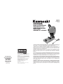 1
1
-
 2
2
-
 3
3
-
 4
4
-
 5
5
-
 6
6
-
 7
7
-
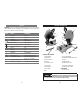 8
8
-
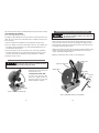 9
9
-
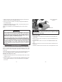 10
10
-
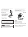 11
11
-
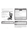 12
12
-
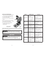 13
13
-
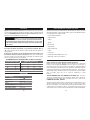 14
14
-
 15
15
-
 16
16
-
 17
17
-
 18
18
-
 19
19
-
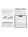 20
20
-
 21
21
-
 22
22
-
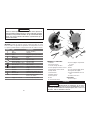 23
23
-
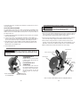 24
24
-
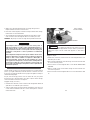 25
25
-
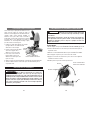 26
26
-
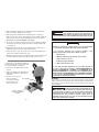 27
27
-
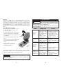 28
28
-
 29
29
-
 30
30
-
 31
31
-
 32
32
-
 33
33
-
 34
34
-
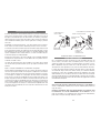 35
35
-
 36
36
-
 37
37
-
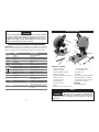 38
38
-
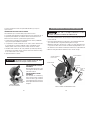 39
39
-
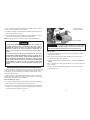 40
40
-
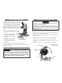 41
41
-
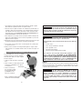 42
42
-
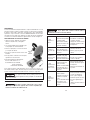 43
43
-
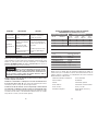 44
44
-
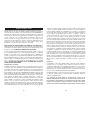 45
45
-
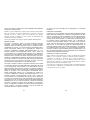 46
46


Kawasaki 691783 Manuel utilisateur
- Catégorie
- Outils électroportatifs
- Taper
- Manuel utilisateur
dans d''autres langues
- English: Kawasaki 691783 User manual
- español: Kawasaki 691783 Manual de usuario
Documents connexes
-
Kawasaki 691221-1HR Manuel utilisateur
-
Kawasaki 691225 Manuel utilisateur
-
-
-
-
-
-
-
-