
français
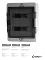
a Disjoncteur
b Alimentation 220-240 V
c Boîtiers de gestion
d Relais
e Trous de fixation
english
deutsch
a Schutzschalter
b 220-240 V Stromnetz
c Steuerungskasten
d Relais
e Befestigungslöcher
a Circuit breaker
b 220-240 V supply
c Driving boxes
d Relay
e Fixation holes
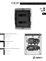
Coret d’alimentation pour VBP ms
Supply box for VBP ms
Elektrischer Versorgungsblock für VBP ms
MS
6 x
DCP notice d’installation - installation instructions - Montageanleitung
version produit - product version - Produkt-Version / n.4 (05/2011)
+
-
n°3n°2
n°1
3 4
2 oors
>
T°
VBP
5 7
-
T
+
-
p
+
-
p
+
-
+
-
p
+
1 2 3 4 5 6 7 8 9 10 11 12
13 14 15 16 17 18 19 20 21 22 23 24
SIEMENS
LOGO! Power
6EP1322-1SH01
N
L1
+ + - -
SIEMENS
LOGO! Power
6EP1322-1SH01
N
L1
+ + - -
O-OFF
N
N
+
-
n°3n°2
n°1
3 4
2 oors
>
T°
VBP
5 7
-
T
+
-
p
+
-
p
+
-
+
-
p
+
1 2 3 4 5 6 7 8 9 10 11 12
13 14 15 16 17 18 19 20 21 22 23 24
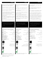
e
a b c d
photo non contractuelle - not contractual photo - Nicht vertragliche Foto

2
français
Le DCP* est un coffret électrique IP65 intégrant
l’ensemble des composants nécessaires au
fonctionnement du ventilateur VBP ms**.
Il peut être directement raccordé sur le réseau
220-240 V~ et alimenter jusqu’à 6 ventilateurs.
Ses 2 boîtiers de gestion intégrés permettent
de piloter les ventilateurs connectés :
- La puissance d’alimentation des ventilateurs
est automatiquement réglée en fonction de la
position des curseurs sur les boîtiers.
- Lorsqu’un ventilateur est à l’arrêt, cela provo-
que l’arrêt des autres ventilateurs connectés
au même boîtier.
- Une unique sonde de température connectée
au coffret permet d’adapter la vitesse de fonc-
tionnement des ventilateurs aux conditions
de température.
- Un relais permet le pilotage d’un témoin de
défaut ou de fonctionnement.
english deutsch
L’installation du système complet doit
être réalisée par un professionnel, dans le
respect des normes en vigueur (sécurité
électrique, CEM). Un IP 55 doit être
garanti.
* distribué en France par ACTHYS - Réf. CDH4-6
** distribué en France par ACTHYS sous la
marque «HELYS» - Réf.H315
DCP is an electric box IP65 integrating all the
components necessary to the working of the
VBP ms fan.
It is possible to connect it directly on the 220-
240 V~ supply, and can supply up to 6 fans.
Its 2 driving boxes make possible the control of
the connected fans :
- The power supply of the fans is automatically
regulated according to the position of the
cursors on the boxes.
- When one of the fans is off, the other fans
connected to the same box also stop.
- A single temperature sensor connected to the
supply box allows the adaptation of the fan
working speed to the conditions temperature.
- A relay enables the driving of a breakdown or
working indicator.
The installation of the complete device
must be realized by a professional,
respecting the current standards
(electrical security, CEM). IP 55 must be
guaranteed.
DCP ist ein IP65 elektrisches Gehäuse, das die
zum Betrieb des VBP ms notwendigen Kompo-
nenten integriert.
Es besteht die Möglichkeit das Gehäuse auf
dem 220-240 V~ Stromnetz zu schalten, es
kann bis 6 Lüfter versorgen.
Seine 2 integrierten Steuerungskasten erlaubt,
die eingeschalteten Ventilatoren zu steuern :
- Die Stromversorgungskraft der Ventilatoren
wird automatisch nach der Schaltstellung der
Cursoren auf den Gehäusen geregelt.
- Bei stehendem Ventilator stellen sich die zum
selben Gehäuse gehörenden Ventilatoren ab.
- Ein zum Gehäuse alleiniges verbindetes Tem-
peraturmessgerät passt die Geschwindigkeit
der Ventilatoren an die Temperatur an.
- Eine Relais-Steckdose ermöglicht die Steue-
rung des Defektlichtes bzw. eines Laufslich-
tes.
Die Installation der kompleten Anlage
darf nur von einem Fachmann nach
den gültigen Regelungen (elektrische
Sicherung, CEM) ausgeführt werden.
IP55 soll garantiert sein.
220-240 V~ / 50 Hz
70 W
4,3 kg
340 x 460 x 160 mm
ABS ou SB
Gris clair et transparent
2000 m
2
-25°C - +60 °C
5% - 100%
double isolation
conforme aux normes
EN 61000-6-3 : 2007,
EN 61000-6-1 : 2007 et
EN 61010-1 : 2001
220-240 V~ / 50 Hz
70 W
4.3 kg
340 x 460 x 160 mm
ABS or SB
Light gray / translucid
2000 m
2
-25°C - +60 °C
5% - 100%
double insulation
standards
EN 61000-6-3 : 2007,
EN 61000-6-1 : 2007 and
EN 61010-1 : 2001 compliant
Tension
Puissance maxi
Poids
Dimensions (L x h x p)
Matière (corps)
Couleur
Altitude maximale
d’installation du produit
Degré de pollution
Plage de température
du lieu d’installation
Plage d’humidité relative du
lieu d’installation
Power supply
Max power
Weight
Dimensions (L x h x p)
Material (body)
Color
Max altitude
of the product installion
Pollution degree
Temperature range of
the installation place
Relative humidity range
of the installation place
Caractéristiques et domaine d’emploi Features and uses
Les données techniques de ce document sont sujet-
tes à des modifications sans avis préalable.
The technical data of this document are subject to
change without previous information.
Änderungen der technischen Angaben dieses Doku-
ments behählt sich Aereco S.A. vor.
220-240 V~ / 50 Hz
70 W
4,3 kg
340 x 460 x 160 mm
ABS oder SB
durchsichtiges hell Grau
2000 m
2
-25°C - +60 °C
5% - 100%
Doppelisolierung
Entsprechend Standards
EN 61000-6-3 : 2007,
EN 61000-6-1 : 2007 und
EN 61010-1 : 2001
Spannungsversorgung
maxi. Leistungsaufnahme
Gewicht
Abmessungen (L x h x p)
Material
Farbe
maxi. Einbauhöhe des
Produktes
Verschmutzungsklasse
Verwendungstemperatur
Verwendungs rel. feuchti-
gkeit
Eigenschaften und Nutzbereich

3
3
4
2
1
Sonde de température
Trous de fixation
Cache-trous
Mask-holes
Masken-Löcher
Fixation holes
Befestgungslöcher
Boîtier étanche IP65
Témoin de défaut (non fourni)
Témoin de fonctionnement (non fourni)
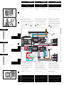
Le diamètre extérieur de tous les
câbles doit être compris entre 5,5 mm
et 10 mm afin d’assurer l’étanchéité du
coffret électrique. La section utile des
câbles doit être supérieure ou égale
à 1,5 mm². Utiliser des câbles prévus
pour une installation à l’extérieur.
Um die Dichtheit des Schaltschranks zu
sichern, soll das Aussendurchmesser
von aller Kabel zwischen 5,5 und 10
mm beintragen sein. Die brauchbare
fläche der Kabel soll wenigstens
1,5 mm2 sein. Benützen Sie Kabel
geeignet für eine Außereinbau.
The external diameter of wires must
be between 5,5 mm and 10 mm
in order to guarantee the water
tightness of the electrical box. The
useful section must be higher or
equal at 1.5 mm². Use cables adapted
to outside installation.
english deutsch
français
Remove the cover of the elec-
trical box.
Retirer le couvercle du coffret
électrique.
Entfernen Sie den vorderen
Deckel des elektrichen Gehäu-
ses.
Installation of
the electrical box
Montage des elektrischen
Gehaüse
Installation du coret
électrique
Breakdown indicator (not supplied)
Working indicator (not supplied)
Temperature sensor
Waterproof box IP65
Defektlicht (nicht mitgeliefer)
Laufslicht (nicht mitgeliefert)
Temperaturmessgerät
Dichtes Gehaüser IP65
A
A
A
B
B
B
C
C
C
D
D
D
E
F
F
F
E
E
français
english
deutsch
IP65
IP65
IP65
IP65
VBP
+
-
n°3n°2
n°1
3 4
2 oors
>
T°
VBP
5 7
-
T
+
-
p
+
-
p
+
-
+
-
p
+
1 2 3 4 5 6 7 8 9 10 11 12
13 14 15 16 17 18 19 20 21 22 23 24
SIEMENS
LOGO! Power
6EP1322-1SH01
N
L1
+ + - -
SIEMENS
LOGO! Power
6EP1322-1SH01
N
L1
+ + - -
O-OFF
N
N
+
-
n°3n°2
n°1
3 4
2 oors
>
T°
VBP
5 7
-
T
+
-
p
+
-
p
+
-
+
-
p
+
1 2 3 4 5 6 7 8 9 10 11 12
13 14 15 16 17 18 19 20 21 22 23 24
+
-
p
+
-
p
+
-
p
+
-
p
+
-
p
+
-
p
230 V~ 5A max
24
T
-
+
230 V~
+
-
n°3n°2
n°1
3 4
2 oors
>
T°
VBP
5 7
-
T
+
-
p
+
-
p
+
-
+
-
p
+
1 2 3 4 5 6 7 8 9 10 11 12
13 14 15 16 17 18 19 20 21 22 23 24
SIEMENS
LOGO! Power
6EP1322-1SH01
N
L1
+ + - -
O-OFF
N
N
C
C
C
C
C
C
D
E
A B
Phase
Neutral
F
Fixer le coffret électrique
verticalement à un endroit
accessible, partiellement protégé
des intempéries et proche des
ventilateurs, en perçant les trous
de fixation E prévus à cet effet.
Ajoutez les cache-trous F sur
les vis.
Fix the electrical box vertically
at an accessible place, partially
protected from bad weather
and close to the fans, by
drilling the dedicated fixation
holes E. Put the mask-holes
F on the screws.
Befestigen Sie das elektrische
Gehäuse senkrecht an einem
zugänglichen Ort, teilweise vor
Unwetter geschützt und in der
Nähe der Lüfter, mit den dazu vor-
gesehenen Befestigungslöcher
E. Stellen Sie die Masken-Lö-
cher F auf den Schrauben.
Raccorder les composants
externes au coffret électrique
tels qu’indiqué sur le schéma
de branchement, en utilisant
les passe-câble fournis et en
les serrant suffisamment pour
assurer l’étanchéité.
Revisser le couvercle sur le
coffret.
Schliessen Sie die externen
Komponente an Gehäuse an,
wie auf dem Anschlussplan
erwähnt, dank der gelieferten
Kabeldurchführungen und
schrauben Sie sich fest genug,
um die Dichtheit zu sichern.
Den Deckel wieder
festschrauben.
Connect the external
components to the electrical
box as indicated on the
connection diagram above,
using the supplied wires
blockers and tighten them
enough to insure the tightness.
Fix back the cover.
x 4
schéma indicatif :
la sortie des fils doit être effectuée
sur le dessous du boîtier.
indicative plan:
electric wires must output the
under the box.
Anzeigendes Schema : das Ausfuhr
der elektrischen Fäden soll von
unten durchgeführt werden.

4
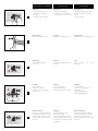
Marche normale
Témoin vert : clignotement lent.
Cela signifie que tout fonctionne
correctement. Fermer ensuite le
coffret à l’aide de la poignée et
de la clé.
Normales Betrieb
Grünes LED: langsames Blinken.
Es bedautet dass alles richtig
funktionniert. Danach das
Gehäuse mit Schlüssel und Griff
schliessen.
Working
Green test-button: slow
intermittent signal.
This means that the system is
working normally. Then close the
door by the mean of the handle
and the key.
n°3
n°2
n°1
n°
T°
by
CCP
3 4
2 oors
>
5 7
1
Start up / Use EinschaltungMise en route / Utilisation
n°3
n°2
n°1
n°
T°
by
CCP
3 4
2 oors
>
5 7
2
Réglages
Vérifier les indications de :
- nombre de ventilateurs
connectés
- nombre total de niveaux
Einstellung
Prüfen Sie folgende Angaben :
- Zahl der verbundenen Venti-
latoren
- Zahl der Stufen
Adjustment
Check the indications of :
- number of connected fans
- total number of floors / levels
Mise en route
Enclencher le disjoncteur.
Einschaltung
Schalten Sie den Schutzschalter
ein.
Start-up
Engage the circuit breaker.
3
n°3
n°2
n°1
n°
T°
by
CCP
3 4
2 oors
>
5 7
4
Démarrage
Tout s’allume quelques
secondes.
Start
Alles leuchtet ein paar
Sekunden.
Kontrolle
1 bis 20 Zyklen
- Grünes Kontrolllämpchen :
brennend,
- Rote Kontrolllämpchen :
abweschelndes Brennen.
Starting
Every lights are lighting a few
seconds.
5
Contrôle
de 1 à 20 cycles
Témoin vert : allumé,
Témoins rouges : allumage à
tour de rôle.
Control
from 1 to 20 cycles
Green test-button: lit,
Red test button: lit in rotation.
n°3
n°2
n°1
n°
T°
by
CCP
3 4
2 oors
>
5 7
1 > 20

5
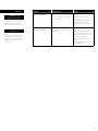
Signal Signication Action
3 témoins rouges
allumés en continu.
Le nombre de ventilateurs correc-
tement branchés ne correspond
pas à la consigne renseignée sur
le commutateur.
- Déclencher le disjoncteur
(OFF)
- Effectuer les corrections
éventuelles
(branchements, nombre de
ventilateurs renseigné)
- Réenclencher le disjoncteur
(ON)
1 témoin rouge
allumé en continu.
Ce ventilateur est en panne
et provoque l’arrêt des autres
ventilateurs.
- Déclencher le disjoncteur
(OFF)
- Vérifier si aucun obstacle blo-
que le moteur du ventilateur
- Effectuer les corrections éven-
tuelles (branchements)
- Réenclencher le disjoncteur
(ON)
Si le problème persiste, contac-
ter le distributeur.
Les pannes non résolues doi-
vent faire l’objet du remplace-
ment du matériel concerné.
Ce produit ne requiert pas d’en-
tretien particulier. Une vérifica-
tion du bon fonctionnement du
produit peut être réalisée une
fois par an.
Traitement des
dysfonctionnements
Maintenance
français

6
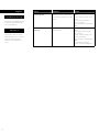
Signal Meaning Action
3 red test-buttons
uninterrupted lit.
The number of correctly connec-
ted fans does not correspond to
the instruction mentioned on the
switch.
- Disconnect the circuit breaker
(OFF)
- Carry out the possible correc-
tions
(connections, number of
connected fans)
- Reconnect the circuit breaker
(ON)
1 red test-button uninter-
rupted lit.
This fan is out of order, so the
other fans stop.
- Disconnect the circuit breaker
(OFF)
- Check if no obstacle blocks
the motor fan
- Carry out the possible correc-
tions (connections)
- Reconnect the circuit breaker
(ON)
If the problem continues,
please contact the distributor.
The unsolved breakdowns must
involve the replacement of the
concerned material.
This product does not require
particular maintenance. A check
of the good working of the
product can be realized once
a year.
Breakdown processing
Maintenance
english

7
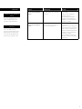
Signal Bedeutung Lösung
3 kontinuierliche bren-
nende rote Kontrollläm-
pchen.
Die Anzahl der Ventilatoren ents-
pricht die Gaben des Kommuta-
tors nicht.
-Schalten Sie den Schutzschal-
ter aus (OFF)
-Führen Sie die eventuelle
Korrekturen durch
(Verbindungen,Anzahl der
angegebenen Ventilatoren)
-Schalten Sie den Schutzschal-
ter wieder ein (ON)
1 kontinuierliche bren-
nende rote Kontrollläm-
pchen.
Dieser Ventilator funktionniert
nicht und führt zum Stillstand
der anderen Ventilatoren.
-Schalten Sie den Schutzschal-
ter aus (OFF)
- Prüfen Sie, dass kein Hinderniss
den Ventilatormotor behindert
-Führen Sie die eventuelle Kor-
rekturen (Verbindungen) durch
-Schalten Sie den Schutzschal-
ter wieder ein (ON)
Wenn das Problem andauert,
nehmen Sie mit Ihrem Händler
Kontakt auf
Die nicht geklärten Pannen
müssen zum Ersetzten des
betroffenes Objektes führen.
Dieses Produkt erfordert
keine besondere Wartung. Eine
Überprüfung des guten Funk-
tionierens des Produktes kann
realisiert sein einmal pro Jahr.
Funktionsstörungenbehan-
dlung
Wartung
deutsch

D5010_C
AERECO S.A
62 rue de Lamirault
COLLEGIEN
77 615 Marne la Vallée cédex 3
FRANCE
www.aereco.fr
Assistance technique et SAV :
Contacter votre revendeur.
À défaut, vous pouvez contacter
directement la société
Aereco S.A. :
AERECO S.A
62 rue de Lamirault
COLLEGIEN
77 615 Marne la Vallée cédex 3
FRANCE
www.aereco.com
Technical assistance and after-
sales service:
Contact your retailer.
If necessary, contact directly
Aereco S.A.:
AERECO S.A
62 rue de Lamirault
COLLEGIEN
77 615 Marne la Vallée cédex 3
FRANCE
www.aereco.de
Technisches Hotline und Kun-
dendienst :
Bitte rufen Sie Ihre Verkäufer an.
Sonst nehmen Sie Kontakt
direkt mit Aereco S.A. auf.
français english deutsch
-
 1
1
-
 2
2
-
 3
3
-
 4
4
-
 5
5
-
 6
6
-
 7
7
-
 8
8


dans d''autres langues
- English: Aereco VBP Installation guide
- Deutsch: Aereco VBP Installationsanleitung
Documents connexes
-
Aereco VBP Guide d'installation
-
-
-
-
-
-
-
-
-