CTC Union xDSL Series Manuel utilisateur
- Catégorie
- Les routeurs
- Taper
- Manuel utilisateur
Ce manuel convient également à

User's Manual


1
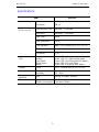
Contents
Overview.............................................................................................. 3
Features.............................................................................................. 4
Applications......................................................................................... 4
Specifications...................................................................................... 5
Packing................................................................................................ 6
Appearance......................................................................................... 7
Front Panel....................................................................................... 7
Rear Panel........................................................................................ 8
Important Safety Instructions............................................................. 9
Installation...........................................................................................11
Hardware Setup.................................................................................13
Point-to-point Operation.....................................................................14
Console Operation.............................................................................15
Console Operation / Configuration....................................................16
Cables.................................................................................................18

2

SDTU-01 SDSL V.35 DSU
3
Overview
The SDTU-01 SDSL DSU with V.35 interface is a data access DSU
modem with the latest multi-rate SDSL (Symmetrical Digital Subscriber
Line) technology offering both long range and high speed data
transmission with rates from 144Kbps up to 2320Kbps. The
transmitting data rate may be adapted for the best "rate vs. range"
performance for efficient and stable data transmission.
The SDTU-01 uses the 2B1Q line code with echo cancellation to
transmit its high data rate over a single twisted pair of telephone wire
without being affected by bridge taps or mixed cable links. It also
provides high immunity to background noise and enables transmission
over multiple pair cables.

SDTU-01 SDSL V.35 DSU
4
Features
4 High speed SDSL transport over single twisted Copper pair
telephone line
4 2B1Q line code
4 Symmetrical Multi-rate data transmission from 144Kbps to
2320Kbps
4 Simple operation
4 Low power consumption
4 Transparent data over SDSL
4 Point-to-point data transmission service
4 Supervision via RS-232 Craft port
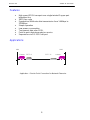
Applications
LAN
Router
SDTU-01
LAN
Router
SDTU-01
Application : Point-to-Point Connection for Network Extension

SDTU-01 SDSL V.35 DSU
5
Specifications
Item SDTU-01
Data Port Interface V.35
Connector DB-25
WAN Port --
SDSL Line I/F
Transmission Rate : 144 Kbps – 2320 Kbps
Data Rate : 144 Kbps – 2320 Kbps
Line Code 2B1Q
Line Impedance
135 Ω
Test Standard ANSI T1E1.413/94-006; ETSI ETR 152
Connection Loops One Pair (2-wire)
Connector RJ-11
Indicators
LED
Power
Activity
Link Status
WAN Status
Alarm
Green LED, indicate power and operation
Green LED, DSL data activity status
Green LED, Local Data port Link status
Green LED, DSL Link Status
Green LED, Self-test & Error status
OAM&P Local ASCII Terminal via EIA RS-232 Port
Environment Temperature
Humidity
0°C ~ 50°C
5% ~ 95%
Dimensions
(WxDxH)
CPE 220mm X 169mm X 40mm
Electrical Power Input
Power Consumption
12VDC via AC Adapter
Less than 5 Watts

SDTU-01 SDSL V.35 DSU
6
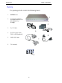
Packing
This package shall contain the following items:
1
2
3
4
5
6
1. SDTU-01 unit
2. AC Adapter (120VAC
for North America, and
220-240VAC for
Europe)
3. RJ-11 Cable
4. RS-232 Serial Cable,
DB-9 to DB-9(optional)
5. DB25-V35 Cable
6. This manual

SDTU-01 SDSL V.35 DSU
7
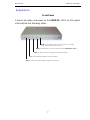
Appearance
Front Panel
Connect all cables and power on the SDTU-01, LED’s on front panel
shall indicate the following status.
ALM: On when there is an error, if it remains On all the
time, please call customer service.
WAN: On when there is an active and connected
WAN
.
(SDSL Sync.)
PWR: On when the power supply is properly connected.
ACT: On and blink when there are data activities.
LINK: On when V.35 port is properly connected to Router.

SDTU-01 SDSL V.35 DSU
8
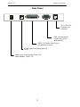
Rear Panel
RJ11, SDSL for
connection to
local loop
DB9, console port for
connection to ASCII
data terminal
DB25, V.35 serial Data Port, for
connection to a router
4P DIP switch, for setting speed &
CO/RT
Power Jack, for connecting to a AC-DC
power adapter, 12VDC, 1A
V.35
DC-IN
TERMINAL
WANRATE
DIP ON

SDTU-01 SDSL V.35 DSU
9
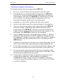
Important Safety Instructions
The following safety instructions apply to the SDTU-01:
1. Be sure to read and follow all warning notices and instructions.
2. The maximum recommended ambient temperature for SDTU-01 is
40(104) Care must be taken to allow sufficient air circulation or
space between units when the SDTU-01 is installed inside a closed
rack assembly. The operating ambient temperature of the rack
environment might be greater than room temperature.
3. Installation in a rack without sufficient air flow can be unsafe.
4. Racks should safely support the combined weight of all equipment.
5. The connections and equipment that supply power to the SDTU-01
should be capable of operating safely with the maximum power
requirements of the SDTU-01. In the event of a power overload, the
supply circuits and supply wiring should not become hazardous. The
input rating of the SDTU-01 is printed on the nameplate.
6. The AC adapter must plug in to the right supply voltage, i.e. 120VAC
adapter for North America and 230VAC adapter for Europe. Be sure
the supplied AC voltage is correct and stable. If the input AC voltage is
over 10% lower than the standard may cause to malfunction of the
SDTU-01 unit.
7. Installation in restricted access areas must comply with Articles 110-16,
110-17, and 110-18 of the national Electrical Code, ANSI/NFPA 70.
8. Do not allow anything to rest on the power cord of the AC adapter, and
do not locate the product where anyone will walk on the power cord.
9. Do not service the product by yourself. Opening or removing covers
can expose you to dangerous high voltage points or other risks. Refer
all servicing to qualified service personnel.
10. General when installed in the final configuration, the product must
comply with the applicable safety standards and regulatory
requirements of the country in which it is installed. If necessary,
consult the appropriate regulatory agencies and inspection authorities
to ensure compliance.

SDTU-01 SDSL V.35 DSU
10
11. A rare condition can create a voltage potential between the earth
grounds of two or more buildings. If products installed in separate
building are interconnected, the voltage potential can cause a
hazardous condition. Consult a qualified electrical consultant to
determine whether or not this phenomenon exists and, if necessary,
implement corrective action before interconnecting the products. If the
equipment is to be used with telecommunications circuit, take the
following precautions:
4 Never install telephone wiring during a lightning storm.
4 Never install telephone jacks in wet location unless the jack is specially
designed for wet location.
4 Never touch uninsulated telephone wires or terminals unless the
telephone line has been disconnected at the network interface.
4 Use caution when installing or modifying telephone lines (other than a
cordless telephone) during an electrical storm. There is a remote risk of
electric shock from lightning.
4 Do not use a telephone or other equipment connected to telephone
lines to report a gas leak in the vicinity of the leak.

SDTU-01 SDSL V.35 DSU
11
L
A
N
W
A
N
TERMINAL
V.
3
5
D
C
-
I
N
RATE
1
2
3
4
DI
P
O
N
Router
L
AN
W
A
N
TERMINAL
V
.3
5
D
C
-
IN
RATE
1
2
3
4
DI
P
ON
L
A
N
W
A
N
TERMINAL
V
.
3
5
D
C
-
IN
RATE
1
2
3
4
DI
P
ON
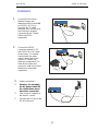
Installation
1.
Connect the local loop
(twisted copper pair
telephone wire) to the WAN
port (SDSL, RJ-11) by
using the RJ-11 cable
attached. Be sure this local
loop had been properly
connected to the Central
Office side SDSL
equipment.
2.
Connect the DB-25
connector marked "V.35"
with "DB-25 to V.35" cable
to the router. To correctly
connect with the router
cable. Please refer to the
section of "Cables" for
detail pin assignment. The
other end of router will
connect to LAN (Local Area
Network) or other data
equipment.
3.
Power connection --
• Warning : Do not apply
the AC power before all
the connections above
have been connected.
• Plug in the AC Adapter to
the wall AC socket
• Connect the DC jack to the
DC-IN of the unit

SDTU-01 SDSL V.35 DSU
12
L
A
N
W
A
N
TERMINAL
V.
3
5
D
C
-
IN
RATE
1
2
3
4
D
IP
ON
RS232
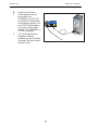
4.
Terminal Connection --
• A data terminal can be
connected to the
TERMINAL port (RS-232)
of the unit for configuration
& monitoring purpose. Use
the RS-232 serial cable to
connect to a ASCII data
terminal. The TERMINAL is
VT-100 compatible.
• A PC with data terminal
emulation software
installed, can be connected
via serial COM port in data
terminal mode.

SDTU-01 SDSL V.35 DSU
13
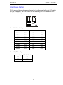
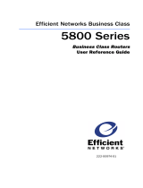
Hardware Setup
DSL rate and terminal type can be set up by adjusting the 4-pole DIP switch
on the rear panel. Sw. 1 to Sw. 3 are for adjusting the DSL rate while Sw. 4
is for termination type.
1. DSL Rate Setting
Rate No.1 No.2 No.3
144K ON ON ON
272K ON ON OFF
400K ON OFF ON
528K ON OFF OFF
784K OFF ON ON
1168K OFF ON OFF
1552K OFF OFF ON
2320K OFF OFF OFF
2. CO/RT configuration
Terminal type DIP SW No. 4
CO ON
RT OFF
ON

SDTU-01 SDSL V.35 DSU
14
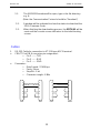
Point-to-point Operation
1. The SDTU-01 should be located on each side of the connection. One
side must be set to "CO" and the other side must be set to "RT". Refer
to the section on "Hardware Setup" for the CO & RT setup.
2. Insure that both CO & RT SDTU-01s are set to the same DSL rate. For
example, 784Kbps.
3. Make sure that both CO & RT SDTU-01s have been connected to the
Routers properly.
4. Check the WAN LED on the SDTU-01 -- it will remain lit when the Link
is successfully established. The DSL training process may take around
one minute and the WAN LED will flash during the training process.
5. After the DSL link is established, check the router setup. Both CO & RT
side routers must be set to use the same Link Protocol, i.e. PPP or
Frame Relay link. Both side routers must also set the same
parameters. Otherwise, they may fail to communicate with each other
even though the DSL link is ready.
6. Follow the Router manual to set the IP and other parameters. When
the router is properly set, you are ready to use the high-speed
connection between the two networks. You may test the data
transportation speed by using the "Ping" command or FTP file transfer.

SDTU-01 SDSL V.35 DSU
15
Console Operation
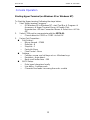
Starting Hyper-Terminal (on Windows 95 or Windows NT)
To Start the Hyper-terminal, following the steps below:
1. Start "Hyper-terminal" program --
− On Windows 95 or Windows NT : start Tool Bar à Program à
Accessory à Hyper Terminal Group à Double Click
Hypertrm.exe à Enter Connection Name à Select Icon à Click
OK
2. Select COM port to communicate with the SDTU-01--
− Choose direct to COM1 or COM2 à click OK
3. Set up Port Properties --
n Port Setting :
− Bit per second : 57600
− Data bits : 8
− Stop bits : 1
− Parity bit: None
− Flow Control : None
n Settings :
− Function, arrow, and ctrl keys act as : Windows keys
− Emulation : Auto-detect
− Back-scroll buffer lines : 500
n ASCII Setup:
− Echo typed characters locally
− Line delay : 0 milliseconds
− Character line feeds t incoming line ends : enable

SDTU-01 SDSL V.35 DSU
16
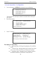
Console Operation / Configuration
1. Turn on the power of SDTU-01, the terminal screen will display :
The booting screen will stay for about 6 seconds before entering the
Main Menu.
2. Main Menu display--
3. Select "0" display --
Descriptions of select items --
3.1. Bit Pump Status : Bit Pump Chip detection; OK or NG(No
Good).
3.2. Terminal Type : Indicate whether the Terminal Type of this
unit is set for CO(Central Office) or RT(Remote Terminal).
3.3. Operation Status : Indicates the DSL operation mode as
UP(Normal Operation) or DN(Down, During Start up).
SDSL V.35 DSU Software Version xxx
0. Show DSL Status
1. Upgrade Operation Software
2. Upgrade SDSL Firmware
Select Function Item ?__
Firmware Version xxx Software Version xxx
Bitpump Status: OK Terminal Type: RT
Operation Status: DN V.35 OFF_Line
Noise Margin: -15.5 dB Data Rate: 2320 kbps
Press any key to return main manual….
Booting Code_Version: xxx
DRAM BANK0 Check O.K.
DRAM BANK1 Check O.K.
Wait, booting now……….

SDTU-01 SDSL V.35 DSU
17
3.4. V35 : To indicate whether V.35 is Active(ON_Line) or Not
Active(Off_Line).
3.5. Noise Margin : Shows Noise Margin value.
3.6. Data Rate : Shows current transmission data rate (e.g.
1552Kbps)
4. Select "1" display -- Upgrade Operation Software
4.1. The XMODEM window will be opened, type in the file directory
e.g. A:
(Note: the Communication Protocol should be "Xmodem")
4.2. A window will be activated to show the status to download the
Operation Software Code.
4.3. When finishing the downloading process, the SDTU-01 will be
reset and the console screen will be back to initial booting
screen.
5. Select "2" display -- Upgrade SDSL Firmware
Are you sure you want to upgrade "Operation Software" ?
(Y/N)
Y
Enter Password : 2000
Start to Receive Program from Console by X_MODEM !
Are you sure you want to upgrade "SDSL Firmware" ? (Y/N)
Y
Enter Password : 2000
Start to Receive Program from Console by X_MODEM !

SDTU-01 SDSL V.35 DSU
18
5.1. The XMODEM window will be open, type in the file directory
e.g. A:
(Note: the Communication Protocol should be "Xmodem")
5.2. A window will be activated to show the status to download the
SDSL Firmware Code.
5.3. When finishing the downloading process, the SDTU-01 will be
reset and the console screen will return to the initial booting
screen.
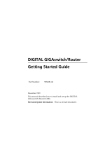
Cables
1. RS-232 Cable for connection to VT-100 type ASCII terminal
4 CRAFT Port DB-9 connector pin assignment :
− Pin 2 ------ TXD
− Pin 3 ------ RXD
− Pin 5 ------ GND
4 Parameter :
− Data Speed : 57600 bps
− Parity : None
− Stop Bit : 1 bit
− Character Length : 8 Bits
2
3
5
4
6
7
8
2
3
5
4
6
7
8
male
male
2
3
5
4
6
7
8
2
3
5
4
6
7
8
male
female
La page est en cours de chargement...
-
 1
1
-
 2
2
-
 3
3
-
 4
4
-
 5
5
-
 6
6
-
 7
7
-
 8
8
-
 9
9
-
 10
10
-
 11
11
-
 12
12
-
 13
13
-
 14
14
-
 15
15
-
 16
16
-
 17
17
-
 18
18
-
 19
19
-
 20
20
-
 21
21


CTC Union xDSL Series Manuel utilisateur
- Catégorie
- Les routeurs
- Taper
- Manuel utilisateur
- Ce manuel convient également à
dans d''autres langues
- English: CTC Union xDSL Series User manual
Autres documents
-
 Efficient Networks Network Router 5800 Manuel utilisateur
-
 Cabletron Systems GIGAswitch GSR-8 Getting Started Manual
-
Omron ZS-DSU Le manuel du propriétaire
-
 Paradyne ACCULINK 3160 Supplementary Manual
-
Terratec NOXON A540 Le manuel du propriétaire
-
Terratec NOXON iRadio 300 Le manuel du propriétaire
-
Terratec NOXON iRadio 360 Le manuel du propriétaire
-
Cisco Systems 1700 Manuel utilisateur
-
Tripp Lite DTEL2 Manuel utilisateur
-
Nortel Networks Switch 4000 Manuel utilisateur


