Toro 18in Gas Straight-Shaft Trimmer Manuel utilisateur
- Catégorie
- Coupe-herbe
- Taper
- Manuel utilisateur
Ce manuel convient également à

Trimmer/Brushcutter
Model No. 51973—260000001 & Up
Model No. 51993—260000001 & Up
English (EN), French (FR), and Spanish (ES)
WARNING:
To reduce the risk of injury, the user must read and understand the operator’s manual. Save this manual.
Form No. 3356-125 Rev. A

2
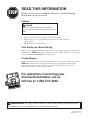
READ THIS INFORMATION
Before you use your new trimmer/brushcutter, read the following
helpful hints to get you started.
Fueling
DANGER:
Gasoline is extremely flammable and explosive.
A fire or explosion from gasoline will burn you and
others.
1. Obtain a clean container that is approved for use with gasoline.
2. Mix all of the 2-cycle oil provided with 1 US gallon of 87-octane, unleaded
gasoline (50:1).
3. Fill the trimmer’s gas tank carefully.
Cold Starting vs. Warm Starting
When you restart the trimmer/brushcutter and you are not sure whether the engine is still warm, set
the choke lever to RUN (Choke Open) and pull the starter cord. If the engine does not start within
5 pulls, see To Start a Cold Engine later in this manual.
Flooded Engine
Will the engine start? If not, it may be flooded. Relax, this is easy to correct. Set the choke lever to
RUN (Choke Open). Squeeze the trigger and pull the starter cord quickly for 10 to 12 pulls.
If the engine does not start, refer to Troubleshooting later in this manual or call toll-free at
1-866-574-9242 (US) or 1-866-574-9243 (Canada).
WARNING: The engine exhaust from this product contains chemicals known to the State
of California to cause cancer, birth defects, or other reproductive harm.
Printed in USA
All rights reserved
STOP
1-866-574-9242
CAL
L
For questions concerning your
trimmer/brushcutter, call us
toll free at 1-866-574-9242.

3
Table of Contents
Introduction ...................................................................................................................................................................................4
Safety Rules .............................................................................................................................................................................. 5-6
Symbols .................................................................................................................................................................................... 6-7
Product Labels ..............................................................................................................................................................................8
Features ................................................................................................................................................................................... 9-11
Product Specifications ...........................................................................................................................................................9
Assembly ............................................................................................................................................................................... 12-16
Unpacking ............................................................................................................................................................................12
Connecting the Attachment to the Upper Shaft ...................................................................................................................13
Removing the Attachment from the Upper Shaft ................................................................................................................
13
Attaching the Front Handle .................................................................................................................................................
13
Attaching the Shoulder Strap ...............................................................................................................................................14
Attaching the Grass Deflector ..............................................................................................................................................14
Converting from Brushcutter to Trimmer ............................................................................................................................15
Converting from Trimmer to Brushcutter ............................................................................................................................16
Operation ............................................................................................................................................................................... 17-20
Applications .........................................................................................................................................................................
17
Mixing the Fuel ....................................................................................................................................................................
17
Filling the Tank ....................................................................................................................................................................17
Starting the Product .............................................................................................................................................................
18
Stopping the Product ............................................................................................................................................................18
Operating the Trimmer ........................................................................................................................................................19
Operating the Brushcutter ....................................................................................................................................................20
Cutting Tips .........................................................................................................................................................................
20
Maintenance .......................................................................................................................................................................... 21-24
Emissions Maintenance Schedule ........................................................................................................................................21
Cleaning the Product ............................................................................................................................................................
21
Servicing the Product ...........................................................................................................................................................21
Replacing the Cutting Line ............................................................................................................................................ 21-22
Replacing the Spool .............................................................................................................................................................22
Checking the Fuel Cap .........................................................................................................................................................23
Cleaning the Air Filter .........................................................................................................................................................
23
Replacing the Spark Arrester ...............................................................................................................................................
23
Replacing the Spark Plug .....................................................................................................................................................24
Storing the Product ..............................................................................................................................................................24
Transporting the Product .....................................................................................................................................................24
Troubleshooting ..........................................................................................................................................................................25
Warranty ................................................................................................................................................................................ 26-28
Table of Contents

4
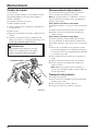
Introduction
Thank you for purchasing a Toro product.
We would like for you to be completely satisfied with your new product, so feel free to contact an authorized service dealer
for help with service, genuine Toro parts, or other information you may require.
Whenever you contact an authorized service dealer, always know the model and serial numbers of the product. These num-
bers will help the service representative provide exact information about your specific product. You will find the model and
serial number decal located on the motor housing.
For your convenience, write the product model and serial numbers in the space below.
Model No.
Serial No.
Read this manual carefully to learn how to operate and maintain your product correctly. Reading this manual will help you
and others avoid personal injury and damage to the product. Although Toro designs, produces, and markets safe, state-of-the-
art products, you are responsible for using the product properly and safely. You are also responsible for training persons you
allow to use the product about safe operation.
The Toro warning system in this manual identifies potential hazards and has special safety messages that help you and others
avoid personal injury, even death. DANGER, WARNING, and CAUTION are signal words that identify the level of hazard.
However, regardless of the hazard, be extremely careful. One other word, “Note,” highlights information.
Signal Word Explanation
DANGER Indicates an imminently hazardous situation which, if not avoided, will result in death or
serious injury.
WARNING Indicates a potentially hazardous situation which, if not avoided, could result in death or
serious injury.
CAUTION Indicates a potentially hazardous situation which, if not avoided, may result in minor
or moderate injury. It may also be used to alert against unsafe practices that may cause
property damage.
Note Advises you of additional information concerning the operation or maintenance of the
equipment.
Introduction

5
This product has been designed and manufactured to
meet or exceed the requirements of the current version of
ANSI B175.3, safety requirements for gasoline-powered
string trimmers and brushcutters.
Physical Condition of the Operator. Do not operate
this product when tired, ill, or under the influence of
alcohol, drugs, or medication.
Clothing Requirements. Always wear long heavy
pants, boots, and gloves. Do not wear loose cloth-
ing, jewelry, short pants, sandals, or go barefoot.
Secure hair so that it is above shoulder level to avoid
entanglement in moving parts.
Protective Accessories Requirements. Wear eye
protection marked to comply with ANSI Z87.1
standards when operating this product. Wear hearing
protection during extended periods of operation.
Condition of Trimmer Before Use. Inspect the
product before each use. Replace damaged parts.
Check for fuel leaks. Make sure all fasteners are
in place and secure. Replace cutting attachment
parts that are cracked, chipped, or damaged in any
way. Make sure the cutting attachment is properly
installed and securely fastened. Be sure the cutting
attachment shield is properly attached and in the
position recommended by the manufacturer. Use
only flexible, non-metallic line recommended by the
manufacturer. For example, never use wire or wire-
rope, which can break off and become a dangerous
projectile.
Proper Stance. Keep firm footing and balance. Do
not overreach. Keep the cutting attachment below
waist level. Keep all parts of your body away from
the rotating cutting attachment and hot surfaces.
Exhaust Gases. Never start or run the product inside
a closed room or building; breathing exhaust fumes
can cause illness or death.
Fueling. Mix and pour fuel outdoors where there are
no sparks and flames. Slowly remove the fuel cap
only after stopping the engine. Do not smoke while
fueling or mixing fuel. Wipe spilled fuel from the
product. Move at least 30 ft. (9 m) away from the
fueling source and site before starting the engine.
Work Area. Clear the area to be cut before each
use. Remove all objects, such as rocks, broken glass,
nails, wire, or string, that can be thrown or become
Safety Rules
WARNING:
Read and understand all instructions. Failure to follow all instructions may result in serious personal injury
as well as damage to the product.
entangled in the cutting attachment. Clear the area of
children, bystanders, and pets. At a minimum, keep
all children, bystanders, and pets outside a 50 ft.
(15 m) radius. Because there still may be a risk of
injury to bystanders from thrown objects, bystanders
should be encouraged to wear eye protection. If you
are approached while operating the product, stop the
engine and the cutting attachment.
Dangerous Environments. To avoid falling, do not
use the product in damp or wet locations.
Controlling the Product. During carburetor adjust-
ments the cutting attachment may spin. Therefore,
you should wear protective equipment and observe
all safety instructions when adjusting the carbure-
tor. For products equipped with a clutch, be sure the
cutting attachment stops turning when the engine
idles. When the product is turned off, make sure the
cutting attachment has stopped before setting down
the product.
Use the Right Product. Use the product for the
intended purpose only.
Condition of Brushcutter Before Use. The handles
shall be mounted according to the manufacturer’s
instructions. Do not attach any blade to a product
without proper installation of all required parts. Fail-
ure to use the proper parts can cause the blade to fly
off and seriously injure the operator and/or bystand-
ers. Discard blades that are bent, warped, cracked,
broken, or damaged in any way.
Use the Right Equipment. Always use the barrier
bar on the front handle and the shoulder strap with
the brushcutter.
Blade Thrust. Blade thrust may occur when the
spinning blade contacts an object that it does not im-
mediately cut. A blade thrust can be violent enough
to cause the product and/or operator to be propelled
in any direction, and possibly lose control of the
product. Blade thrust can occur without warning if
the blade snags, stalls, or binds. This is more likely to
occur in areas where it is difficult to see the material
being cut.
Stopping the Product. A coasting blade can cause
injury while it continues to spin after the engine is
stopped or throttle is released. Maintain proper con-
trol until the blade has completely stopped rotating.
Safety Rules

6
Symbols
This engine is equipped with a spark arrester muffler. It is a violation of California Public Resource Code Section
4442 to use or operate this engine without a spark arrester muffler on any forest-covered, brush-covered, or grass-
covered land. Other states or federal areas may have similar laws.
This spark ignition system complies with Canadian ICES-002.
Save these instructions. Refer to them frequently and use them to instruct others who may use this product. If you
loan someone this product, loan these instructions also.
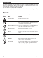
Symbols
The following symbols are located on the product. Please study them and learn their meaning. Proper interpretation of these
symbols allows you to operate the product better and safer.
Symbol Name Explanation
Safety Alert Symbol Precautions that involve your safety.
Read the Operator’s Manual Read the operator’s manual before starting or operating this product.
Failure to follow operating instructions and safety precautions in the
operator’s manual can result in serious injury.
Wear Eye and Hearing Protection Wear eye protection which is marked to comply with ANSI Z87.1 as
well as hearing protection when operating this equipment.
Keep Bystanders Away Keep all bystanders at least 50 feet (15 m) away.
Ricochet Thrown objects can ricochet and result in personal injury or property
damage.
No Blade Do not install or use any type of blade on a product displaying this
symbol.
Blade Thrust Beware of blade thrust. Products authorized for blade use will
display this symbol to warn of blade thrust.
Gasoline and Oil Use unleaded gasoline intended for motor vehicle use with an octane
rating of 87 [(R + M) / 2] or higher. This product is powered by a
2-cycle engine and requires pre-mixing gasoline and 2-cycle oil.
Safety Rules

7
Symbols
The following signal words and meanings are intended to explain the levels of risk associated with this
product.
SYMBOL SIGNAL MEANING
DANGER: Indicates an imminently hazardous situation, which, if not avoided, will
result in death or serious injury.
WARNING: Indicates a potentially hazardous situation, which, if not avoided, could result
in death or serious injury.
CAUTION: Indicates a potentially hazardous situation, which, if not avoided, may result
in minor or moderate injury.
CAUTION: (Without Safety Alert Symbol) Indicates a situation that may result in property
damage.
Symbols
SERVICE
Servicing requires extreme care and knowledge and should
be performed only by a qualified service technician. For
service we suggest you return the product to your nearest
AUTHORIZED SERVICE CENTER for repair. When
servicing, use only identical replacement parts.
WARNING:
To avoid serious personal injury, do not attempt
to use this product until you read thoroughly and
understand completely the operator’s manual. If you
do not understand the warnings and instructions in the
operator’s manual, do not use this product. Call Toro
customer service for assistance.
The operation of any power tool can result in foreign objects being thrown into your
eyes, which can result in severe eye damage. Before beginning power tool operation,
always wear safety goggles or safety glasses with side shields and, when needed, a full
face shield. We recommend Wide Vision Safety Mask for use over eyeglasses or standard
safety glasses with side shields. Always use eye protection which is marked to comply
with ANSI Z87.1.
WARNING:
SAVE THESE INSTRUCTIONS

8
Product Labels
Product labels and instructions are easily visible to the operator and are located near any area of potential danger.
Replace damaged or lost labels.
Part No. 940627032 (Shoulder Strap)
Part No. 940686006
Part No. 940230129 Part No. 940657004
Part No. 940627017
Product Labels
50' 15m
50' 15m
OFF ON
TO START
Set switch to ON
Push bulb 8x
Set choke lever to “FULL”
SQUEEZETHROTTLETRIGGER FULLY (THRU STEP
7)
and pull starter handle sharply (no more than 4x)
Set choke lever to “HALF”
Pull starter handle until engine runs
,
no more
than 6 pulls
.
For Help Call: 1-866-574-9242
Run engine at Full Throttle for 20 seconds, set
choke lever to "RUN"
pantone 2945c
pantone 362c
black
RYOBI ART WORK
Art Part No.: 940686006
Label Part No.: 940686006
Refer to Drawings for Dimensions
Rev.000
Part No. 308207004 (Air Box Cover)

9
Features
Product Specifications
Name Specification
Engine 25.4 cc Full Crank
Cutting Width
Model No. 51973 18 in.
Model No. 51993 8 in. for brushcutter, 18 in. for trimmer
Line Size .095 in.
Weight
Model No. 51973 13-1/2 lbs.
Model No. 51993 13-1/2 lbs.
Specifications

10
Features
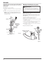
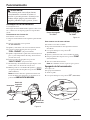
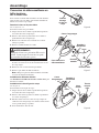
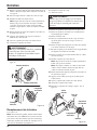
Know Your Trimmer/Brushcutter
See Figure 1.
The safe use of this product requires an understanding of the
information on the tool and in this operator’s manual as well
as a knowledge of the project you are attempting. Before
use of this product, familiarize yourself with all operating
features and safety rules.
Common Features
Engine
The engine is powerful and easy to start. It is effectively
counterbalanced, which allows for less vibration and more
durability.
Dual Line
The dual line permits more efficient cutting than a single
line.
Grass Deflector
The grass deflector helps protect you from flying debris.
Ergonomic Design
The design of the product provides for easy handling. It is
designed for comfort when operating in different positions
and at different angles.
Brushcutter Features
(Model No. 51993)
Blade
The Tri-Arc
®
blade allows you to brushcut weeds, vines, and
light brush.
Brushcutter Guard
The brushcutter guard helps protect you from the blade and
from flying debris.
Shoulder Strap
The brushcutter includes a shoulder strap that helps support
the product.
Barrier Bar
The handle on the brushcutter contains a barrier bar that
restrains the operator in position and maintains a proper
distance between the operator and the blade.
Features

11
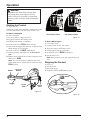
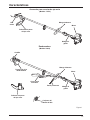
Figure 1
Features
Barrier
Bar
Brushcutter
Guard
Shoulder
Strap
Trigger
Handle
Blade
Straight Shaft Trimmer
(Model No. 51973)
Engine
Trigger
Handle
Front Handle
Straight Shaft
Grass Deflector
Dual
Line
Engine
Front Handle
Brushcutter
(Model No. 51993)
Features
Straight Shaft
Grass Deflector
String Head
Assembly

12
Unpacking
This product requires assembly.
Carefully remove the items from the box. Make sure
that all items listed in the packing list are included.
Inspect the product carefully to make sure no breakage
or damage occurred during shipping.
Do not discard the packing material until you have care-
fully inspected and satisfactorily operated the product.
If any parts are damaged or missing, please call toll free
1-866-574-9242 for assistance.
Packing List
Upper Shaft (Power Head)
Attachment Shaft (Cutting Head)
Handle (Model No. 51973)
Handle with Barrier (Model No. 51993)
Straight Shaft Grass Deflector
String Head Assembly (Model No. 51993)
Oil
Head Locking Tool (Model No. 51993)
Shoulder Strap (Model No. 51993)
Hanger Cap
Operator’s Manual
Assembly
Unpacking
WARNING:
If any parts are damaged or missing, do not
operate the product until the parts are replaced.
Failure to heed this warning could result in seri
-
ous personal injury.
WARNING:
Do not attempt to modify this tool or create
accessories not recommended for use with this
tool. Any such alteration or modification is
misuse and could result in a hazardous condition
leading to possible serious personal injury.
WARNING:
Do not start trimmer until assembly is complete.
Failure to comply could result in accidental
starting and possible serious personal injury.

13
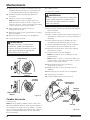
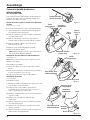
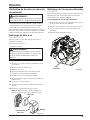
Assembly
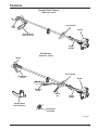
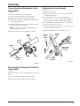
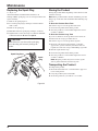
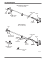
Connecting the Attachment to the
Upper Shaft
See Figure 2.
To connect the attachment to the upper shaft:
1. Loosen the knob by turning it counterclockwise.
2. Remove the end cap from the attachment shaft.
3. Align the button on the attachment shaft with the guide
recess on the upper shaft.
4. Slide the attachment shaft into the upper shaft until the
attachment shaft clicks into place.
Note: You may need to turn the attachment shaft to
properly align the two shafts.
5. Tighten the knob securely by turning it clockwise.
Removing the Attachment from the
Upper Shaft
See Figure 2.
Follow these steps to remove the attachment from the upper
shaft.
1. Loosen the knob by turning it counterclockwise.
2. Push the button while pulling out the attachment.
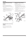
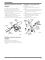
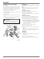
Attaching the Front Handle
See Figure 3.
To attach the front handle:
1. Remove the slotted Torx
™
screws to separate the handle
from the handle support.
2. Press the handle onto the top of the upper shaft, no
less than 10 in. (25.4 cm) from the center of the trigger
handle, angling the handle toward the trigger handle.
3. Place the handle along the upper shaft to a position that
allows for comfortable operation.
4. Place the handle support on the bottom of the tube on the
opposite side of the front handle.
5. Secure the handle with the slotted Torx
™
screws.
Assembly
Figure 2
Button
Attachment
Shaft
Guide
Recess
Upper
Shaft
Knob
Figure 3
Slotted
Torx
Screw
Front
Handle
Trigger
Handle
Barrier Bar
(Model Nos.
51993)
Handle
Support

14
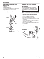
Attaching the Grass Deflector
WARNING:
The line cutting blade on the grass deflector
is sharp. Avoid contact with the blade. Failure
to avoid contact can result in serious personal
injury.
Note: To protect the operator, always be sure to attach the
grass deflector.
To Attach the Straight Shaft Grass Deflector
See Figure 5.
To attach the straight shaft grass deflector:
1. Remove the screw from the grass deflector.
2. Insert the tab on the mounting bracket in the slot on the
grass deflector.
3. Align the screw hole in the mounting bracket with the
screw hole in the grass deflector.
4. Insert the screw through the mounting bracket and into
the grass deflector.
5. Tighten the screw securely.
Figure 5
Assembly
Straight Shaft
Grass Deflector
Tab
Slot
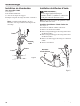
Attaching the Shoulder Strap
Model Nos. 51993
See Figure 4.
To attach the shoulder strap:
1. Connect the latch on the strap to the hanger bracket.
2. Adjust the strap to a comfortable position.
Note: To quickly release the product from the shoulder
strap, sharply pull the quick release tab.
Figure 4
Strap
Latch
Hanger
Bracket
Quick
Release
Tab
Assembly

15
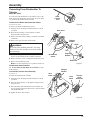
Converting From Brushcutter To
Trimmer
Model No. 51993
To convert from the brushcutter to the trimmer, remove the
blade, remove the brushcutter guard, attach the grass deflec-
tor, and install the trimmer head assembly.
To Remove the Blade and Brushcutter Guard
See Figures 6 and 7.
To remove the blade and brushcutter guard:
1. Align the slot in the flanged washer with the slot in the
gear head.
2. Place the head locking tool through the slot in the
flanged washer and gear head.
3. Remove the blade nut by turning it clockwise (left-hand-
ed threads).
4. Remove the cupped washer and the blade.
WARNING:
Be careful when handling the blade. It is sharp.
Failure to heed this warning can result in serious
personal injury.
5. Remove the flanged washer from the gear shaft and
retain it for the trimmer head assembly installation.
6. Remove the three screws securing the brushcutter guard.
7. Remove the brushcutter guard.
Note: Store the brushcutter parts together for future use.
To Attach the Grass Deflector
See To Attach the Straight Shaft Grass Deflector earlier
in this manual.
To Install the Trimmer Head Assembly
See Figure 8.
To install the trimmer head assembly:
1. Align the slot in the flanged washer with the slot in the
gear head.
2. Insert the head locking tool through the flanged washer
and gear head.
3. Install the drive shaft and trimmer head assembly onto
the gear shaft by turning the drive shaft counterclockwise
(left-handed threads).
4. Tighten the drive shaft securely.
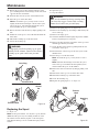
Figure 6
Figure 8
Assembly
Head
Locking
Tool
Figure 7
Slot
Gear Head
Brushcutter
Guard
Flanged
Washer
Blade
Blade Nut
Slot
Cupped
Washer
Gear
Head
Trimmer
Head
Assembly
Drive
Shaft
Flanged
Washer
Assembly
Slot

16
Converting From Trimmer To Brushcutter
Model No. 51993
To convert from the trimmer to the brushcutter, remove the
trimmer head assembly, remove the grass deflector, attach
the brushcutter guard, and install the blade.
To Remove the Trimmer Head Assembly and Grass
Deflector
See Figures 9 and 10.
To remove the trimmer head assembly and grass deflector:
1. Align the slot in the flanged washer with the slot in the
gear head.
2. Insert the head locking tool through the flanged washer
and gear head.
3. Remove the drive shaft and trimmer head assembly by
turning the drive shaft clockwise (left-handed threads).
4. Remove the flanged washer and retain it for the blade
installation.
5. Remove the screw securing the grass deflector.
6. Remove the grass deflector.
Note: Store the trimmer head assembly parts together
for future use.
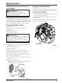
To Attach the Brushcutter Guard
See Figure 11.
Note: To protect the operator, always be sure to attach the
brushcutter guard.
To attach the brushcutter guard:
1. Place the guard onto the gear head as shown.
2. Insert the three hex head screws from the bottom through
the guard into the gear head.
3. Tighten the screws securely and torque to 40-50 in.lb.
To Install the Blade
See Figure 12.
To install the blade:
1. Place flanged washer over the gear shaft with the hollow
side toward the brushcutter guard.
2. Center the blade on the flanged washer, making sure the
blade fits flat and the raised hub goes through the hole in
the blade.
3. Install the cupped washer with the raised center away
from the blade.
4. Place the blade nut onto the gear shaft.
5. Insert the head locking tool through the flanged washer
and gear head.
6. Install the blade nut by turning it counterclockwise (left-
handed threads).
7. Tighten the blade nut and torque to 120 in.lb. minimum
(finger tight plus 1/2 turn).
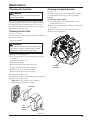
Figure 9
Figure 10
Figure 11
Figure 12
Assembly
Head
Locking
Tool
Gear
Head
Trimmer
Head
Assembly
Drive
Shaft
Flanged
Washer
Straight Shaft
Grass Deflector
Slot
Gear Head
Brushcutter
Guard
Hex Head
Screw
Brushcutter
Guard
Flanged
Washer
Blade
Blade Nut
Cupped
Washer
Gear Shaft
Assembly

17
Operation
Operation
Mixing the Fuel
DANGER:
Gasoline is extremely flammable and explosive.
A fire or explosion from gasoline will burn you
and others.
This product is powered by a 2-cycle engine and requires pre-
mixing gasoline and 2-cycle oil. The oil mix should be 50:1,
using oil that meets or exceeds JASO-FC specifications.
Follow these steps to mix the fuel.
1. Obtain a clean container that is approved for use with
gasoline.
2. Mix the 2-cycle engine oil provided with unleaded gaso-
line in the container, according to the instructions on the
oil carton.
Note: This engine is certified to operate on unleaded gaso-
line intended for automotive use with an octane rating of 87
[(R + M) / 2] or higher. Do not use automotive oil or 2-cycle
outboard oil. Store the container out of the reach of children.
Filling the Tank
WARNING:
Always stop the engine before filling the tank.
Never add fuel to a machine with a running or
hot engine. Move at least 30 ft. (9 m) away from
the refueling site before starting the engine. Do
not smoke while filling the tank.
To fill the tank:
1. Clean the surface around the fuel cap to prevent contami-
nation.
2. Loosen the fuel cap by turning it counterclockwise.
3. Pour the fuel mixture carefully into the tank.
4. Clean and inspect the gasket.
Note: Replace the fuel cap if the gasket is damaged.
5. Install the fuel cap and tighten it by turning it clockwise.
WARNING:
Check for fuel leaks. If you find any leaks,
correct the problem before using the product.
6. Wipe spilled fuel from the product.
7. Move at least 30 ft. (9 m) away before starting the
product.
Note: It is normal for the engine to emit smoke during
use.
WARNING:
Do not allow familiarity with tools to make you
careless. Remember that a careless fraction of a
second is sufficient to inflict serious injury.
WARNING:
Always wear safety goggles or safety glasses
with side shields when operating power tools.
Failure to do so could result in objects being
thrown into your eyes resulting in possible seri
-
ous injury.
WARNING:
Do not use any attachments or accessories not
recommended by the manufacturer of this tool.
The use of attachments or accessories not rec-
ommended can result in serious personal injury.
Applications
You may use this tool for the purposes listed below:
Cutting grass, weeds, and light undergrowth
(all models)
Edging along sidewalks and driveways (all models)
Cutting pulpy weeds, vines, and light brush
(Model No. 51993)
50:1 Gasoline to Oil Mixing Chart
Gasoline Oil
1/2 US gallon 1.3 oz.
1 US gallon 2.6 oz.
2 US gallons 5.2 oz.
1 liter 20 ml
2 liters 40 ml
3 liters 60 ml
4 liters 80 ml
5 liters 100 ml
+ =

18
WARNING:
The product may throw objects during opera-
tion, causing injury to the operator or to by-
standers. Always wear suitable eye protection,
long heavy pants, and boots while operating the
product.
Starting the Product
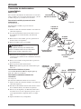
See Figures 13-15.
Starting the product differs depending on whether the engine
is cold or warm. Refer to the label on the air filter cover.
To Start a Cold Engine
To start a cold engine:
1. Lay the product on a flat, bare surface.
2. Toggle the switch to the I (ON) position.
3. Push the primer bulb up to eight times.
4. Set the choke lever to FULL (Choke Closed).
5. Squeeze throttle trigger fully (thru step 7) and pull starter
handle sharply (no more than 4x).
6. Set the choke lever to HALF (Choke Open).
7. Pull starter handle until engine runs, no more than 6
pulls.
8. Run the engine at full throttle for 20 seconds, then set the
choke lever to RUN.
Note: In cooler environments, additional pulls of the
starter handle may be required with the choke lever in the
FULL position.
Figure 14
To Start a Warm Engine
To start a warm engine:
1. Lay the product on a flat, bare surface.
2. Toggle the switch to the I (ON) position.
3. Push the primer bulb up to eight times.
4. Set the choke lever to RUN (Choke Open).
5. Pull the starter cord.
Note: If the product does not start, repeat the previous
steps.
Stopping the Product
See Figure 15.
To stop the product.
1. Release the trigger.
2. Toggle the switch to the O (OFF) position.
Figure 15
Operation
Figure 13
Lock-off
Button
Switch
Starter
Cord
Trigger
Primer
Bulb
Trigger
Switch
Set Choke to FULL
Set Choke to RUN
Operation

19
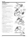
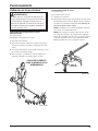
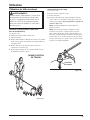
Operating the Trimmer
WARNING:
Always hold the string trimmer away from the
body, keeping clearance between the body and
the product. Any contact with the housing or
string trimmer cutting head can result in burns
and/or other serious personal injury.
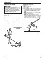
To Operate the Straight Shaft Trimmer
(Model No. 51973)
See Figure 16a.
To operate the straight shaft trimmer:
1. Start the trimmer.
2. Hold the trimmer at waist level with your right hand on
the trigger handle and your left hand on the front handle.
3. Place the product on the right side of your body with the
engine behind and away from your body.
4. Trim grass and weeds in a left-to-right motion with the
line parallel to the ground.
Figure 16a
Figure 16b
Operation
To Advance the Cutting Line
See Figure 16b.
To advance the cutting line:
1. Start the trimmer.
2. Tap the retaining cap lightly on the ground while the mo-
tor is running. The line will only advance with the engine
at full throttle. Do not hold the retaining cap on the
ground.
Note: The line cutting blade on the grass deflector will
cut the line to the proper length.
Note: To help prevent line tangle, tap only once to
lengthen the line. If additional line is required, wait a few
seconds before retapping the retaining cap. Do not allow
the line to wear too short. Keep the cutting line at full
length.
Retaining
Cap
PROPER OPERATING
POSITION
Operation

20
Operating the Brushcutter
(Model No. 51993)
See Figure 17.
To operate the brushcutter:
1. Start the brushcutter.
2. Hold the brushcutter at waist level with your right hand
(arm extended) on the trigger handle and your left hand
on the front handle.
3. Place the product on the right side of your body with the
engine behind and away from your body.
4. Brushcut weeds and vines in a right-to-left motion with
the blade parallel to the ground.
Figure 17
Operation
Cutting Tips
See Figure 18.
1. Avoid hot surfaces by always keeping the tool away
from your body. (Proper operating position is shown in
Figures 16a and 17.)
2. Keep the trimmer tilted toward the area being cut; this is
the best cutting area.
3. The straight shaft trimmer cuts when passing the unit
from left to right. This will avoid throwing debris at the
operator. Avoid cutting in the dangerous area shown in
figure 18.
4. Use the tip of string to do the cutting; do not force string
head into uncut grass.
5. Wire and picket fences cause extra string wear, even
breakage. Stone and brick walls, curbs, and wood may
wear string rapidly.
6. Avoid trees and shrubs. Tree bark, wood moldings, sid-
ing, and fence posts can easily be damaged by the string.
Figure 18
Straight Shaft Trimmer
Dangerous
Cutting Area
Direction of
Rotation
Best Cutting
Area
PROPER OPERATING
POSITION
Operation
La page est en cours de chargement...
La page est en cours de chargement...
La page est en cours de chargement...
La page est en cours de chargement...
La page est en cours de chargement...
La page est en cours de chargement...
La page est en cours de chargement...
La page est en cours de chargement...
La page est en cours de chargement...
La page est en cours de chargement...
La page est en cours de chargement...
La page est en cours de chargement...
La page est en cours de chargement...
La page est en cours de chargement...
La page est en cours de chargement...
La page est en cours de chargement...
La page est en cours de chargement...
La page est en cours de chargement...
La page est en cours de chargement...
La page est en cours de chargement...
La page est en cours de chargement...
La page est en cours de chargement...
La page est en cours de chargement...
La page est en cours de chargement...
La page est en cours de chargement...
La page est en cours de chargement...
La page est en cours de chargement...
La page est en cours de chargement...
La page est en cours de chargement...
La page est en cours de chargement...
La page est en cours de chargement...
La page est en cours de chargement...
La page est en cours de chargement...
La page est en cours de chargement...
La page est en cours de chargement...
La page est en cours de chargement...
La page est en cours de chargement...
La page est en cours de chargement...
La page est en cours de chargement...
La page est en cours de chargement...
La page est en cours de chargement...
La page est en cours de chargement...
La page est en cours de chargement...
La page est en cours de chargement...
La page est en cours de chargement...
La page est en cours de chargement...
La page est en cours de chargement...
La page est en cours de chargement...
La page est en cours de chargement...
La page est en cours de chargement...
La page est en cours de chargement...
La page est en cours de chargement...
La page est en cours de chargement...
La page est en cours de chargement...
La page est en cours de chargement...
La page est en cours de chargement...
La page est en cours de chargement...
La page est en cours de chargement...
La page est en cours de chargement...
La page est en cours de chargement...
La page est en cours de chargement...
La page est en cours de chargement...
La page est en cours de chargement...
La page est en cours de chargement...
La page est en cours de chargement...
La page est en cours de chargement...
La page est en cours de chargement...
La page est en cours de chargement...
La page est en cours de chargement...
La page est en cours de chargement...
La page est en cours de chargement...
La page est en cours de chargement...
-
 1
1
-
 2
2
-
 3
3
-
 4
4
-
 5
5
-
 6
6
-
 7
7
-
 8
8
-
 9
9
-
 10
10
-
 11
11
-
 12
12
-
 13
13
-
 14
14
-
 15
15
-
 16
16
-
 17
17
-
 18
18
-
 19
19
-
 20
20
-
 21
21
-
 22
22
-
 23
23
-
 24
24
-
 25
25
-
 26
26
-
 27
27
-
 28
28
-
 29
29
-
 30
30
-
 31
31
-
 32
32
-
 33
33
-
 34
34
-
 35
35
-
 36
36
-
 37
37
-
 38
38
-
 39
39
-
 40
40
-
 41
41
-
 42
42
-
 43
43
-
 44
44
-
 45
45
-
 46
46
-
 47
47
-
 48
48
-
 49
49
-
 50
50
-
 51
51
-
 52
52
-
 53
53
-
 54
54
-
 55
55
-
 56
56
-
 57
57
-
 58
58
-
 59
59
-
 60
60
-
 61
61
-
 62
62
-
 63
63
-
 64
64
-
 65
65
-
 66
66
-
 67
67
-
 68
68
-
 69
69
-
 70
70
-
 71
71
-
 72
72
-
 73
73
-
 74
74
-
 75
75
-
 76
76
-
 77
77
-
 78
78
-
 79
79
-
 80
80
-
 81
81
-
 82
82
-
 83
83
-
 84
84
-
 85
85
-
 86
86
-
 87
87
-
 88
88
-
 89
89
-
 90
90
-
 91
91
-
 92
92


Toro 18in Gas Straight-Shaft Trimmer Manuel utilisateur
- Catégorie
- Coupe-herbe
- Taper
- Manuel utilisateur
- Ce manuel convient également à
dans d''autres langues
Documents connexes
-
Toro 25cc Power Head Manuel utilisateur
-
Toro 51948 Mode d'emploi
-
-
-
-
-
-
-