Englander 30-NCH Manuel utilisateur
- Catégorie
- Poêle à bois
- Taper
- Manuel utilisateur

INSTALLATION & OPERATION MANUAL
Manufactured By:
England’s Stove Works, Inc.
PO Box 206
Monroe, VA 24574
Rev. 12/2016
Wood Stove
MODELS 30-NC / 50-SNC30 / 50-TNC30
SAVE THESE INSTRUCTIONS

WELCOME!
Introduction
•
PrecautionaryStatements...........3
•
ThankYou!………….…………............4
Installation
•
BeforeInstallation………….….........5
•
CorrectFlueSize……….....................6
•
FlueSystemGuidelines................7
•
Floor&WallProtection..............10
•
SideHeatShields........................12
•
BrickLayout................................12
•
RoomAirBlowers
…………………....13
•
Installation..................................14
•
MobileHomeInstallation...........15
•
OutsideAir
Hook‐Up
...................15
Operation
•
AirInletControl..........................16
•
BuildingaFire............................16
Maintenance
•
GlassCare...................................17
•
GlassGasket................................17
•
DoorGasket................................18
•
FiberBoard.................................18
•
BurnerTubes...............................18
•
Creosote......................................20
•
AshDisposal................................20
Questions
•
HintsandTips.....................................21
PartsandOptions
•
Parts&OptionsList.............................23
•
Legs&PedestalInstallation...............24
Warranty
•
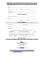
SampleTag..........................................25
•
Warranty
Details
.................................26
•
WarrantyRegistrationForm...............27
ImportantInformation
EPAandSafetyInfo…………….…………29
IMPORTANTNOTES:CLEARANCESMAYONLYBEREDUCEDBYMEANSAPPROVEDBYTHE
REGULATORYAUTHORITYHAVINGJURISDICTION
DONOTCONNECTTOANYAIRDISTRIBUTIONDUCTORSYSTEM.
DONOTBURNGARBAGEORFLAMMABLEFLUIDSSUCHASGASOLINE,NAPHTHAORENGINEOIL.
DONOTUSECHEMICALSORFLUIDSTOSTARTTHEFIRE.

INSTALLATION & OPERATION MANUAL
MODEL NUMBERS: 30-NCP 50-SNC30P 50-TNC30P
30-NCL 50-SNC30L 50-TNC30L
30-NCG 50-SNC30G 50-TNC30G
Thank you for purchasing this product from a fine line of heating equipment.
We wish you many years of safe heating pleasure with your new heating appliance.
Save These Instructions.
NOTE: IF YOU HAVE A PROBLEM WITH THIS UNIT DO NOT RETURN IT TO
THE DEALER. CONTACT CUSTOMER SERVICE @ 1-800-245-6489.
Questions? Need Parts or Options? www.heatredefined.com
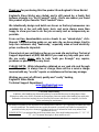
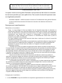
Please Note the Following Precautionary Statements:
CAUTION: This stove must be installed in accordance with the Manufactured Home and Safety
Standard (HUD), CFR 3280, Part 24 and must comply with local building and fire
codes. Failure to follow these instructions could result in property damage, bodily
injury or even death. Keep children, furniture, fixtures and all combustibles away
from any heating appliance.
NOTE: THIS STOVE IS MOBILE HOME AND DOUBLE WIDE APPROVED (WITH OUTSIDE
AIR HOOK-UP) FOR THE PEDESTAL MODEL ONLY – NOT FOR LEG MODELS. DO
NOT INSTALL IN A SLEEPING ROOM. THE STRUCTURAL INTEGRITY OF THE
MOBILE HOME FLOOR, WALL AND CEILING/ROOF MUST BE MAINTAINED.
CAUTION: This unit must be installed in accordance with these instructions and must comply
with local building and fire codes. Failure to do so could result in a chimney or
house fire. Keep children, furniture, fixtures, and all combustible materials away
from any heating appliance. Refer to this owner’s manual for all clearances to
combustible materials.
SAVE THIS MANUAL FOR FUTURE REFERENCE.
Read this entire manual before you install and use your new room heater. If this room
heater is not properly installed, a house fire may result. To reduce the risk of fire,
follow the installation instructions. Failure to follow instructions may result in
property damage, bodily injury, or even death.
England’s Stove Works highly recommends the use of smoke detectors and Carbon Monoxide
detectors with any hearth product, including this unit. Follow all manufacturers’ instructions
when using smoke or Carbon Monoxide detectors
.

4
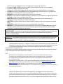
Thank you for purchasing this fine product from England’s Stove Works!
England's Stove Works was started, and is still owned by, a family that
believes strongly in a "Do It Yourself" spirit – that’s one reason you found
this product at your favorite “Do It Yourself” store.
We intentionally design and build our stoves so that any homeowner can
maintain his or her unit with basic tools, and we're always more than
happy to show you how to do the job as easily and as inexpensively as
possible.
From our free, downloadable service sheets to our "wizard-style," click-
through Troubleshooting guide on our web site, we have always tried to
help our customers stay "heat-ready," especially when oil and electricity
prices continue to skyrocket.
Please look at our vast Help section on our web site and call our Technical
Support department at (800) 245-6489 if you need any help with your unit.
We are nearly always able to help “walk you through” any repairs,
problems or questions you may have.
PLEASE NOTE: While information obtained on our web site and through
our 800 number is always free of charge, there will be a service charge
incurred with any “on-site” repairs or maintenance that we may arrange.
Wishing you years of efficient, quality and “comfy” heating,
England’s Stove Works
Technical Support Department
www.HeatRedefined.com
(800) 245-6489
This manual is available for free download on the manufacturer’s web site. It is a copyrighted document and resale
is strictly prohibited. The manufacturer may update this manual occasionally and cannot be responsible for
problems including injuries or damages resulting from the use of information found in any manual from
unauthorized sources.
PLEASE NOTE: If you purchased this model from certain stores, their model number may end in “L” “LC” “H”
“CT”
,
etc. This manual does a
pp
l
y
to those models as well.
CAUTION: Stove is heavy.
In addition, when handling any sheet metal products, be aware that there may be sharp edges or burrs.
Although we make every effort to eliminate any sharp edges, please use caution when handling any metal parts.
Remember to disconnect (unplug) the stove from the power source and allow it to completely cool down
before performing any maintenance.

5
CAUTION
If you have any doubt concerning your ability to complete your installation in a professional-like
manner after reading these instructions, you should obtain the services of an installer who is versed in
all aspects as to the correct and safe installation. Do not use temporary, makeshift compromises
during installation.
BEFORE INSTALLATION OF YOUR APPLIANCE
1. HOT WHILE IN OPERATION. KEEP CHILDREN, CLOTHING AND FURNITURE
AWAY. CONTACT MAY CAUSE SKIN BURNS.
2.
DO NOT BURN GARBAGE OR FLAMMABLE FLUIDS.
3.
Check with the building inspector’s office for compliance with local codes; a permit may be
required.
4.
This appliance requires a masonry or prefabricated chimney listed to ULC S629 (Canada) and
UL103HT (U.S.) sized correctly.
5.
A 6” diameter flue is required for proper performance.
6.
Always connect this unit to a chimney and NEVER vent to another room or inside a building.
7.
DO NOT connect to any duct work to which another appliance is connected, such as a
furnace.
8.
DO NOT connect this unit to a chimney flue serving another appliance.
9.
DO NOT USE CHEMICALS OR FLUIDS TO START THE FIRE.
10.
The connector pipe and chimney should be inspected periodically and cleaned if necessary.
11.
Remember the clearance distances when you place furniture or other objects within the area.
DO NOT store wood, flammable liquids or other combustible materials too close to the unit.
12.
Contact your local fire authority for information on how to handle a chimney fire. Have a
clearly understood plan to handle a chimney fire. In the event of a chimney fire, turn air control
to a closed position and CALL THE FIRE DEPARTMENT.
13.
DO NOT tamper with the combustion air control beyond normal adjustment.
14.
Once the required draw is obtained, operate only with doors closed; open doors slowly when
re-fueling (this will reduce or eliminate smoke from entering the room).
15.
Visit our web site at www.heatredefined.com for helpful information, frequently asked
questions, parts/accessory orders and more. Customer Service: (800) 245-6489.
Note on Outside Air Hookup: You can use an outside air hookup with this unit. We highly recommend it for
homes built since the more air-tight construction standards went into effect. This involves connecting a metal pipe
(usually three inches (3”) in diameter - check your stove - and the pipe can be flex or rigid) from the air inlet pipe
located on the bottom rear of the stove through your floor or wall. The outside end of this pipe should be covered
in some manner (i.e. with a screen) to keep it clear of foreign matter. Be sure to keep it above the snowdrift line
and clear of leaves and other debris. It is necessary to use this hookup if installing in a mobile home or
double-wide – See “Outside Air Connection” section of manual.
A kit is available from England’s Stove Works, Inc. designed for connecting this unit to outside
combustion air. [Part No. AC-OAK3]

6
WHY THE CORRECT FLUE SIZE IS IMPORTANT: 6”
“Draft” is the force that moves air from the appliance up through the chimney. The amount of draft in
your chimney depends on the length of the chimney, local geography, nearby obstructions, and other
factors. Too much draft may cause excessive temperatures in the appliance. An uncontrolled burn or
a glowing red part or chimney connector can indicate excessive draft. Inadequate draft may cause
back puffing into the room and “plugging” of the chimney and/or cause the appliance to leak smoke
into the room through appliance and chimney connector joints.
Today’s solid fuel appliances are much more efficient than in the past. The units are designed to give
you controlled combustion, as well as maximum heat transfer, using less fuel to do so.
The design of your new appliance is such that the exhaust “smoke” is now at lower temperatures than
in the past, therefore requiring proper chimney size to give adequate draft. If your chimney is too
large, the heater will have a difficult time raising the temperature of the flue enough to provide
adequate draft, which can cause a "smoke back," poor burn, or both.
Should you experience such problems, call in a local chimney expert.
With the door closed, the rate of burning is regulated by the amount of air allowed to enter the unit
through the air control. With experience, you will be able to set the control for heat and burning time
desired.
Attempts to achieve higher output rates that exceed heater design specifications can result in
permanent damage to the heater. The recommended wood load is level with the top of the firebricks.
Overloading may prevent sufficient air entering the heater to properly fuel the fire.
Do not tamper with the combustion air control beyond the normal adjustment capacity.
Operate this heater only with the door closed.
DO NOT OVERFIRE. If the heater or chimney connector glows, you are overfiring.
ALWAYS PROVIDE A SOURCE OF FRESH AIR INTO THE ROOM WHERE THE UNIT IS
INSTALLED. FAILURE TO DO SO MAY RESULT IN AIR STARVATION OF OTHER FUEL
BURNING APPLIANCES AND THE POSSIBLE DEVELOPMENT OF HAZARDOUS CONDITIONS.
THIS HEATER IS EXTREMELY HOT WHILE IN OPERATION. SERIOUS BURNS CAN RESULT
FROM CONTACT. CAUTION SHOULD BE OBSERVED, ESPECIALLY WHEN CHILDREN ARE
PRESENT.
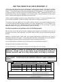
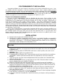
CLEARANCE TO COMBUSTIBLES (See Illustration 1)
Appliance Clearances Unprotected Surfaces Protected Surfaces (NFPA-211)
Side (A) Rear (B) Corner (D) Side (A) Rear (B) Corner (D)
No stove heat shields 20-in 14-in 15-in 12-in 12-in 12-in
Side and Rear shields, single
wall chimney connector
21-in 8-in 15-in N/A N/A N/A
Side and Rear shields, double
wall connector
20-in 5-in** 15-in 12-in 5-in** 12-in
NOTE: Flue Connector to back wall (C):
1. Single wall connector with rear shield = 18”
2. Single wall connector with rear & side shields = 10”
3. Double wall connector with rear & side shields = 7”
NOTE: Flue Connector to corner (E):
1. Single wall connector with rear shield = 20.5”
2. Single wall connector with rear & side shields = 19.5”
**Please Note that the AC-16 blower requires approx. 7” if installed on the rear of the unit
CANADA Clearance to Combustibles (See Illustration 1) – see p. 7 for USA

7
FLUE SYSTEM
1. Existing Flue System
If you have chosen a freestanding unit, this stove is designed to connect to an existing flue system,
such as masonry or a pre-manufactured Class A flue system. If you have a masonry flue system, the
inner liner should be inspected carefully for cracks; if there is no liner in your chimney, we recommend
you install a steel liner or have one installed. If you have an existing pre-manufactured system the
inner liner should be inspected for warping or buckling. Either type chimney system should be
thoroughly cleaned before installing your new stove. We strongly recommend you have a qualified
chimney sweep clean and inspect your entire system, as the sweep can spot problems you might
overlook. The sweep in most cases can make any necessary repairs or recommend a qualified
person to do so.
It is not permissible to connect this unit to a chimney that is servicing another unit.
2. Flue Size
The proper flue size is determined by measuring the inside diameter of the flue collar on the unit.
This stove is equipped with a six inch (6”) TOP EXHAUST FLUE COLLAR. Therefore, the connector
pipe should be six inches (6”) and never less in diameter than the collar on the stove. Your unit may
require an adapter (AC-1677) which will reduce the 6” connector pipe by
1
/
8
”. This is necessary to
accommodate pipe variation from different manufacturers and maintain a good seal. The area of the
chimney liner must also be equal to or greater than the area of the flue collar on the stove. If the area
of the flue is greater than the collar, it should never be more than two and
1
/
2
(2.5) times greater.
The black connector pipe should be 24 gauge steel and eighteen inches (18.0”) from a
combustible wall or eighteen inches (18.0”) from a combustible ceiling. This clearance can be reduced
by using double wall or single wall stovepipe shields.
3. Installation of a New Flue System
Note: Flue systems and flue pipe are not furnished with the unit.
Masonry Flue: In the event that you plan to install or have a system installed, there are several
approaches that you can take. In the middle and late seventies masonry flue systems became very
popular, and today this type system is satisfactory. If you are considering a masonry system, you
should consult with your local building officials for the proper procedures on this type chimney. We
recommend you consult with and have your flue built by a licensed, bonded contractor. Most masonry
chimney systems are placed against an outside wall and extend upward beside the house. The flue
thimble is then inserted through the wall, making the connection with the stovepipe and the vertical
flue. Exercise extreme caution when drilling through the wall -- you must maintain proper clearance
between the connecting liner and any combustible material in the wall.
We also recommend you have a flue clean-out door located at least two feet (2’) below your
thimble for easy cleaning of the system. This door should be made as airtight as possible. It is the
consumer’s responsibility to ensure the chimney system is safe and in good operating condition.
The manufacturer will not be held responsible for an accident attributed to a unit connected to a faulty
chimney system.
CLEARANCE TO COMBUSTIBLES (See Illustration 1)
Appliance Clearances Unprotected Surfaces Protected Surfaces (NFPA-211)
Side (A) Rear (B) Corner (D) Side (A) Rear (B) Corner (D)
No stove heat shields 20-in 14-in 15-in 12-in 12-in 12-in
Side and Rear shields, single
wall chimney connector
19-in 8-in 14-in 12-in 8-in 12-in
Side and Rear shields, double
wall connector
20-in 5-in** 15-in 12-in 5-in** 12-in
NOTE: Flue Connector to back wall (C):
1. Single wall connector with rear shield = 18”
2. Single wall connector with rear & side shields = 10”
3. Double wall connector with rear & side shields = 7”
NOTE: Flue Connector to corner (E):
1. Single wall connector with rear shield = 20.5”
2. Single wall connector with rear & side shields = 19.5”
**Please Note that the AC-16 blower requires approx. 7” if installed on the rear of the unit
USA Clearance to Combustibles (See Illustration 1) – see p. 6 for Canada

8
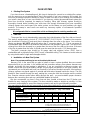
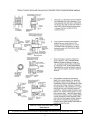
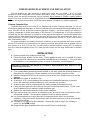
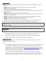
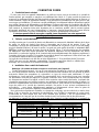
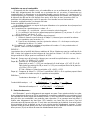
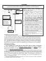
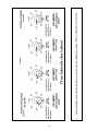
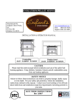
INSTALLATION APPLICATIONS
Illustration 1
18.0” Min.
18” Min.
18.0” Min.
18.0” Min.
NOTE:
1.
Horizontal run not to exceed 6’.
2. Total flue length should not
exceed 25’.
3. Floor protection required:
Min. size 39” x 52.5”.
4. Always check local codes for
clearances, installation, etc.
See Note
(
3
)
See Note
(
3
)
See Note (3)
See Note (3)
And Floor Protection section
B
D
Masonr
y
Chimne
y
(Exterior) Wall
Supported
(Interior) Ceiling
Supported
Single Wall
Chimney
Connector
Lined with
clay tile or
other liner
C
E
A
*IMPROPER INSTALLATION: The manufacturer will not be held responsible for damage caused by
the malfunction of a stove due to improper installation. Do not use makeshift methods or material
which may compromise the installation. England’s will not be liable for consequential or indirect
damages to property or persons resulting from the use of this product.
Call
(
800-245-6489
)
and/or consult a
p
rofessional installer if
y
ou have an
y
q
uestions.
Single Wall
Chimney
Connector
Class “A”
Chimney System
Followallventingsystemmanufacturer’s
installationrequirementsANDtheir
requiredclearances.
18” Min.

9
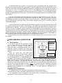
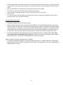
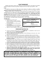
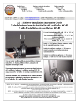
INSTALLATION APPLICATIONS, Cont’d.
Illustration 1b
(InCanada,theinstallationmustconformtoCAN/CSA‐B365whenpassingthroughcombustibleconstruction.)

10
8”
Pre-Manufactured Flue System: In the past few years pre-manufactured flue systems have
become very popular, because this type system is easily installed and, when done correctly, is very
safe. There are many pre-manufactured flue systems on the market, and when making your choice it
should be U.L., (U.L.C. if Canada), B.O.C.A. or I.C.B.O. approved. Any of these systems are
constructed of the proper materials and meet the proper safety standards. Your local dealer normally
handles an approved brand of flue pipe. There are two very popular methods for installation of this
type system.
The first, most popular and least expensive is through the ceiling and out the roof. This is the
most direct route and creates a good draw because it requires less pipe. It is less expensive because
insulated pipe is needed only from the ceiling to the roof and above -- single wall 24 gauge or thicker
pipe is used from the unit to the ceiling if you maintain eighteen inches (18.0”) of clearance from all
combustible material.
The second method for installing a pre-manufactured system is to exit through the wall and run
the system vertically up the outside of the structure. This method is more expensive because more
insulated pipe is required -- you must use insulated pipe through the wall and up the outside of the
structure. In either installation, proper clearances to combustibles should be maintained. Your flue
pipe manufacturer furnishes a wall thimble or ceiling support box and, when installed properly, the
correct clearances are achieved. If you are unable to install this type system your local dealer may be
able to recommend a qualified contractor for this installation. It is the customer’s responsibility to
ensure that his system is installed properly and is in good operating condition.
The manufacturer will not be responsible for an accident caused by a unit connected to a faulty
flue system.
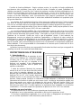
FLOOR AND WALL PROTECTION
1. Floor Protection
You will not need any floor protection if your
floor is constructed of a non-combustible material
such as brick or concrete. If your floor is
constructed with a combustible material such as
hardwood, carpet or linoleum, you must place
protection between the stove and the combustible
material.
There are many floor and wall board
manufacturers, and you should be very cautious
in choosing the proper protection. The type board
you choose should be U.L. rated and listed (ULC
if Canada). After examining the area you plan to place your stove and determining it requires a
board, the next step is to select the proper size. The stove you choose will determine the size
board that is required. The approved protector board should be large enough to provide a
minimum of eight inches (8”) behind the unit, eight inches (8”) on both sides and sixteen inches
(16”) in the front where the door is located. *NOTE: For Canada, 450 mm is required in front and
200 mm on the sides and back. The protection must have an R-value of 1.5 (English units) or
equivalent (See “Installation on a Combustible Floor”). This stove requires a minimum 39.0” x
52.5” floor protection.
Installation on a Concrete Floor
An appliance mounted on a concrete floor does not require floor protection.
Carpeting and any other combustible material must not cover the Floor Protector.
If a combustible surface is applied to the concrete floor, a clearance must be maintained
equivalent to the area reserved for the floor protector.
Floor Protector
-Minimum R
value of 1.5
-Minimum size:
39”W
x 52.5”D
*See NOTE
for Canada

11
Installation on a Combustible Floor
If the appliance is to be installed on a combustible floor or a combustible floor covering, it must
be installed on a 1” thick non-combustible millboard floor protector or a durable equivalent, with a
“R” factor of at least “1.5” (English units) or equivalent. The pad must be installed beneath the
unit, extending 16” (U.S., 450 mm Canada) on the side equipped with a door, and 8” on all other
sides (200 mm Canada). The pad must cover any horizontal chimney connector runs and extend
2” beyond each side.
Alternate Floor Protection:
An easy means of determining if a proposed alternate floor protector meets requirements is to
follow this procedure:
1) Convert specification to R-value:
i R-value is given – no conversion is needed
ii k-factor is given with a required thickness (T) in inches: R = 1/k x T
iii C-factor is given: R = 1/C
2) Determine the R-value of the proposed alternate floor protector:
i Use the correct formula given in step 1 (above) to convert values not expressed as “R.”
ii For multiple layers, add R-values of each layer to determine overall R-value.
3) If the overall R-value of the system is greater than the R-value of the specified floor protector,
the alternate is acceptable.
EXAMPLE:
The specified floor protector should be ¾” thick material with a k-factor of 0.84. The proposed
alternate is 4” brick with a C-factor of 1.25 over 1/8” mineral board with a k-factor of 0.29.
Step (a): Use formula above to convert specification to R-value.
R = 1/k x T = 1/0.84 x .75 = 0.893
Step (b): Calculate R of proposed system.
4” brick of C = 1.25, therefore R brick = 1/C =1/1.25 = 0.80
1/8” mineral board of k = 0.29, therefore Rmin.bd. = 1/0.29 x 0.125 = 0.431
Total R = Rbrick + Rmineral board = 0.8 + 0.431 = 1.231
Step (c): Compare proposed system of R of 1.231 to specified R of 0.893. Since proposed
system R is greater than required, the system is acceptable.
Definitions:
Thermal conductance = C = ____Btu_____ = ____W____
(hr)(ft
2
)(deg F) (m
2
)(deg K)
Thermal conductivity = k = __(Btu)(inch)__ = ____W___ = ____Btu____
(hr)(ft
2
)(deg F) (m)(deg K) (hr)(ft)(deg F)
Thermal resistance = R = (ft
2
)(hr)(deg F) = (m
2
)(deg K)
Btu W
2. Wall Protection
Please see Illustration 1 for clearances to walls. In some areas local codes may require thirty-
six inches (36”) from a combustible; therefore it is very important that you check with local officials.
If you need to place your unit closer to a combustible wall, some protection will be necessary. If an
approved wall board is used this will reduce your clearance by two thirds (2/3); however, a one
inch (1”) air space has to be between the board and the wall. If you have a ceiling flue hook-up,
you will need protection from the floor to the ceiling if you do not meet the normal clearances. If
you have a wall flue hook up, you will need wall protection at least twelve inches (12”) above the
wall thimble.

12
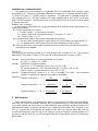
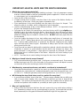
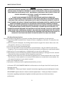
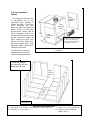
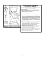
3. Side Heat Shields
This accessory item comes
with the hardware (six (6)
mounting screws) necessary to
install it on the rear of the
stove. This is a two-piece heat
shield, but is installed one
piece at a time. There are pre-
punched holes on each side of
the Rear Heat Shield; while
holding each piece of the Side
Heat Shield in place, align the
pre-punched holes in the Side
Heat Shield with the existing
holes in the Rear Heat Shield,
and fasten with the screws
provided.
See Illustration 1 for
clearances with and without
side heat shields.
Rear Heat
Shield
Side
Heat
Shield
Side
Heat
Shield
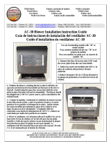
Illustration 3 – Side Heat Shield and Optional Blower Installation
Install AC-30 Optional
Blower on these (4) mounting
holes. See “Optional
Blower” Instructions.
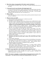
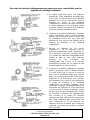
BRICK LAYOUT
1 – (Unmarked on diagram) – 9” x 4” x 1.25” brick (Qty. 25) 3 – 4” x 2 ½ ” x 1.25” brick (Qty. 1)
2 – 4” x 2” x 1.25” brick (Qty. 1) 4 – Metal plate (Ash Drawer Plate, Qty. 1)
4
Steel
Riser
All Unmarked
Brick are Size “1”
3

13
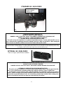
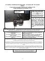
STANDARD (AC-16) BLOWER
OPTIONAL (AC-30) BLOWER
There is a larger, optional blower available.
Install AC-16 Blower here,
using the (4) supplied
mounting screws
The optional heat circulation blower on this stove requires periodic lubrication; this lubrication should be performed no less than
every three months of normal operation. To properly lubricate the blower, use an eye dropper or similar dispensing device to drip
5-7 droplets of SAE 20 oil into the oil port on the side of the blower motor.
ROOM AIR BLOWER: MODEL AC-16
120 VOLTS, 60Hz, 0.75 AMPS, 2900 RPM
DANGER: RISK OF ELECTRIC SHOCK. DISCONNECT POWER BEFORE SERVICING UNIT.
ALWAYS FOLLOW ALL CODES AND OWNER’S MANUALS!
BLOWER MOTOR OPERATING INSTRUCTIONS:
This unit is set up for installation of an optional 2-speed blower motor. The fan speed should be run on
“Low” when the unit is operating at lower burn settings, and set to “High” for high burns. When routing the
p
ower cord, be sure that the cord does not come into contact with an
y
hot surface.
OPTIONAL BLOWER: MODEL AC-30
120 VOLTS, 60Hz, 0.75 AMPS, 3000 RPM
DANGER: RISK OF ELECTRIC SHOCK. DISCONNECT POWER BEFORE SERVICING UNIT.
OPTIONAL BLOWER MOTOR OPERATING INSTRUCTIONS:
This unit is set up for installation of a variable speed optional blower motor. The fan speed should be
run on “Low” when the unit is operating at lower burn settings, and set to “High” for high burns.
See Illustration 3 on the previous page (“Side Heat Shields”) for installation location of your optional
blower. Remove rectangle cover plate if installed. Fasten blower motor to rear heat shield with the four
screws that are provided with your unit. Air should flow upwards when installed. When routing power
cord, be sure that the cord does not come into contact with any hot surface.

14
FREESTANDING PLACEMENT AND INSTALLATION
The first problem you may encounter is getting your stove into your home -- all of our stove
products are well constructed, which makes them rather heavy. Three to four adults can normally
handle a unit, but we still recommend using a handcart. Never attempt to handle a heating product
alone!!! The door and brick can be temporarily removed to lighten the unit (refer to Brick Layout).
After the unit is placed into position, install the spring handles and attach any optional equipment.
Chimney Connector Pipe
The black pipe must be six inches (6”) in diameter and at least 24 gauge steel pipe. Do not use
aluminum or galvanized steel pipe, as it will not withstand the extreme temperatures generated by the
stove. Also, do not use single wall connector pipe as a chimney -- you must connect your stove to a
chimney comparable to those listed earlier in this manual. The crimped end of your pipe should be
inserted into the flue collar and, by doing this, all the pipe will be reversed. If you use this method the
creosote will run back down the inside of your pipe and not out of the joints onto your stove. As a
safety precaution, all joints should be sealed with high temperature silicone (AC-RTV3) and secured
with sheet metal screws.
For proper operation the chimney connector should be as short as possible and never exceed a
six foot (6’) horizontal run. Horizontal runs of chimney connector pipe should have an upward slope of
one quarter of an inch (1/4”) per foot. You will need to maintain eighteen inches (18”) of clearance
from the ceiling and eighteen inches (18”) from the wall, unless you are using double wall or shielded
pipe.
INSTALLATION
1. Remove all parts from inside the stove body.
2. Select the proper location for the stove. These appliances must not be installed any closer
than the minimum clearance to combustible materials shown in Illustration 1. The stove must
be installed on a non-combustible surface as shown in Illustration 1 and Illustration 2.
3. If non-combustible materials have been installed on the walls, obtain the minimum clearances
from either the manufacturer of these materials or the local building inspector’s office.
4. Install the stovepipe INSIDE the flue collar on the top of the stove, between the stove and the
chimney.
5. DO NOT use a grate to elevate the fire.
6. A clearance of 18.0 inches between the stovepipe and combustible materials is required.
Check with authorities having jurisdiction in your area with any questions.
7. All pipe sections must be connected with the male (crimped) end toward the stove.
8. Fasten the stove pipe to the flue collar by the use of three sheet metal screws. Do the same
at each additional joint to make the entire installation rigid.
9. Maintain the required diameter flue for the entire installation.
10. If you are connecting the stove to an old masonry flue, be sure to have it inspected for cracks
and general condition. Resizing with a stainless steel liner may be required.
11. It is recommended that no more than two 90-degree bends be used in the stovepipe
installation. More than two 90-degree bends may decrease the amount of draw, and possibly
cause smoke spillage.
12. A damper is not required in this installation. Remove the damper plate in the chimney or
secure it in the OPEN position.
13. Single wall flue pipe assemblies must not exceed 10 feet in overall length.
FAILURE TO FOLLOW THE MINIMUM CLEARANCE REQUIREMENTS MAY RESULT IN AN
UNSAFE INSTALLATION.

15
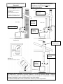
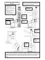
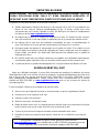
CHIMNEY
Mobile Home Installation
Secure the heater to the floor using the two holes in the pedestal. The wood stove MUST be
secured to the floor of the mobile home using lag bolts and the holes provided in the bottom of the unit
for this purpose. Use a #8 copper wire to ground stove to frame of mobile home. If the unit is on a
combustible surface, you will need to drill matching holes in the floor protection that you choose (see
Floor Protection section). Do not disturb the structural integrity of the home, and be sure the unit is
permanently electrically grounded to the chassis of your home. Remember that outside combustion
air is mandatory, and not to install the unit in a sleeping room of the home.
Outside Air Connection
When installing this model in a mobile home or double wide it is necessary to supply the
combustion air into the unit from outside the dwelling. NOTE: THIS STOVE IS MOBILE HOME AND
DOUBLE WIDE APPROVED (WITH OUTSIDE AIR HOOK-UP) FOR THE PEDESTAL MODEL ONLY
– NOT FOR LEG MODELS.
This can be done by running a thin gauge three inch (3”) pipe (flex or rigid) from the air inlet pipe
located on the rear of the stove through the floor or wall (measure pipe to ensure you obtain the
correct size). The outside end of this pipe should be covered in some manner (i.e. screen) to keep it
clear of foreign matter. Be sure to keep it above the snowdrift line and clear of leaves and other
debris. If you are installing this stove in a regular dwelling this connection is not necessary, but is
recommended in air-tight homes.
A kit is available from England’s Stove Works, Inc. designed for connecting this unit to outside
combustion air. [Part No. AC-OAK3]
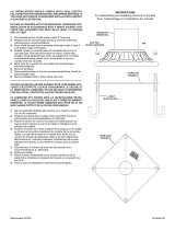
REFER TO CHIMNEY AND CHIMNEY CONNECTOR MANUFACTURER’S INSTRUCTIONS
WARNING: INSTALL VENT AT CLEARANCES SPECIFIED BY THE
VENT MANUFACTURE
R
3 Ft. min. from
Roof Penetration
Min. overall
height from floor
15 Ft.
CONTACT YOUR LOCAL BUILDING AUTHORITY FOR
APPROVED METHODS OF INSTALLATION
1. This appliance requires a masonry or pre-
manufactured chimney listed to UL103HT sized
correctly (ULC S629 if Canada).
2. If a masonry chimney is used, it is advisable to
have your chimney inspected for cracks, and check
the general condition before installing your unit.
Relining may be required to reduce the flue
diameter to the appropriate functional size.
3. To help ensure a good draft, the top of the chimney
should be at least 3 feet above the point of
penetration through the roof, and be at least 2 feet
higher than any point of the roof within 10 feet.
4. The chimney connector shall not pass through an
attic, roof space, closet, concealed space, floor,
ceiling, wall, or any partition of combustible
construction. (Canada: Where passage through a
wall or partition of combustible construction is
desired, the installation shall conform with
CAN/CSA-B365).
5. The minimum overall height of your chimney
should be 15 feet from the floor.
6. Do not use makeshift compromises during
installation.
Illustration 5
Single wall flue pipe
assemblies must not
exceed 10 feet in
overall length.
2 Ft. higher than
nearest point of roof
within 10 ft.

16
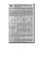
CONTROL SETTINGS for Air Inlet Control
Burn Rate Inlet Air Setting
Low Fully Closed
Med. Low ¼ Open
Med. High ¾ Open
Hi
g
h Full
y
O
p
en
OPERATION
Do not use a grate or elevate the fire. Build the wood fire directly on the bricks. When the stove is
used for the first time, solvents in the paint will smoke off as the stove “cures.”
WOOD –
This heater is designed to burn natural wood only. Higher efficiency and lower emissions
generally result when burning air-dried seasoned hardwood, as compared to softwood or to green or
freshly-cut hardwood.
Use only dry, seasoned wood. Green wood, besides burning at only 60 percent of the fuel value
of dry wood, deposits creosote on the inside of the stove and along the chimney. This can cause
extreme danger of chimney fire. To be called “seasoned,” wood must be dried for a year.
Regardless of whether the wood is green or seasoned, it should be stored in a ventilated, sheltered
area to allow proper drying during the year. Wood should be stored beyond recommended
clearances from combustibles.
DO NOT BURN: Treated Wood, Garbage, Solvents, Trash, Cardboard, Colored Paper or Coal.
FIRST FIRE –
Remember to ventilate well.
Allow the stove to cure before burning for
long periods of time at high temperatures.
Flat spots on the painted surface are
normal.
Shiny spots on the painted surface (before burning) are normal.
Call Customer Service at (800) 245-6489 if you have any questions.
BUILDING A FIRE
1. Open the air inlet control fully (NOTE: The control is located under the ash drawer. Pulling
out on the control opens it).
2. Place a small amount of crumpled paper in the stove.
3. Cover the paper with a generous amount of kindling in a “teepee” shape, and a few small
pieces of wood.
4. Ignite this fuel and close the door most of the way (leave it open slightly).
5. Add larger pieces of wood as the fire progresses, being careful not to overload. Do not fill the
firebox beyond the firebrick area. A coal bed of (ideally) 1” to 2” should be established to
achieve optimum performance.
6. This unit is designed to function most effectively when air is allowed to circulate to all areas of
the firebox. A good way of achieving this is to rake a small (1” to 2” wide) “trough” in the
center of the coal bed, from front to back, prior to loading the fuel.
7. Once fuel has been loaded, close the door and fully open the air inlet control, until the fire is
well established (approximately 20 minutes), being careful not to over-fire.
8. Readjust the air inlet control to the desired burn rate. If excessive smoke fills the firebox, open
the air inlet control slightly, until flames resume and the wood is sufficiently ignited. Basically,
Closed = “Low;” ½ Way Open = “Medium;” and Fully Open = “High.”
9. When refueling, adjust the air control to the fully open position. When the fire brightens,
open the door VERY slowly and carefully. This will prevent gases from igniting and causing
smoke and flame spillage.
10. At this point you may add fuel, being careful not to overload.
NEVER USE GASOLINE, GASOLINE-TYPE LANTERN FUEL, KEROSENE, CHARCOAL
LIGHTER FLUID, OR SIMILAR LIQUIDS TO START OR ‘FRESHEN UP’ A FIRE IN
THIS HEATER. KEEP ALL SUCH LIQUIDS WELL AWAY FROM THE HEATER WHILE
IT IS IN USE.

17
GLASS CARE
The following use and safety tips should be observed:
1. Inspect the glass regularly for cracks or breaks. If you detect a crack or a break, extinguish
the fire immediately, and contact your dealer or Customer Service at (800) 245-6489 for
replacement (or log on to www.heatredefined.com ).
2. Do not slam the door or otherwise impact the glass. When closing door, make sure that logs
or other objects do not protrude and impact the glass.
3. Do not clean the glass with materials which may scratch (or otherwise damage) the glass.
Scratches on the glass can develop into cracks or breaks.
4. Never attempt to clean the glass while the unit is hot. If the deposit is not very heavy, normal
glass cleaners are adequate with a plain, non-abrasive scouring pad. Heavier deposits may
be removed with the use of an oven cleaner.
5. NEVER put substances that can ignite explosively inside the unit, since even small explosions
in confined areas can blow out the glass.
6. This unit has an airwash system, designed to reduce deposits on the glass.
GASKET REPLACEMENT
After extensive use, the sealing material which provides glass and door seal may need to be
replaced if it does not sustain its resilience. Inspect the glass and door seal periodically to ensure
proper seal. If the gaskets become frayed or worn, replace immediately. Contact your dealer or
Customer Service at (800) 245-6489 or www.heatredefined.com for approved replacement parts.
The following steps should be followed for replacement of the glass gasket:
1. Ensure that the appliance is not in operation, and is thoroughly cooled.
2. Remove the screws and glass holders.
3. Lift glass out.
4. Remove the old gasket, and clean the glass.
5. Replace the new gasket, starting at the bottom of the glass and working along the edges. Be
sure to center the gasket channel on the glass.
6. Trim the gasket to length and butt the ends together.
7. Replace the glass and holders in the door. Tighten, being sure not to over-tighten the screws.
REPLACE GLASS ONLY WITH HIGH-TEMPERATURE ROBAX PYROCERAM OF THE
PROPER SIZE AND THICKNESS.
You may order parts and options on our web site: www.heatredefined.com ,
or by calling (800) 516-3636 (parts orders only, call 800-245-6489 for technical questions).

18
The following steps should be followed for replacement of the door gasket:
1. Ensure the appliance is not in operation and is thoroughly cooled.
2. Remove the old door gasket and clean the gasket channel.
3. Using an approved high-temperature gasket cement, apply a thin coat in the bottom of the
channel.
4. Starting at the hinge side of the door, work into the channel around the door unit, trim to length
and butt the ends together.
5. Close the door and allow three to four hours for the cement to set before restarting any fire.
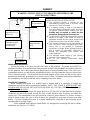
FIBER BOARD: CARE & MAINTENANCE
THIS WOOD HEATER UTILIZES NEW TECHNOLOGY, WHICH INCLUDES CERAMIC FIBER
BOARD THAT IS LOCATED IN THE FIREBOX, AND RESTS ON TOP OF
FOUR STAINLESS STEEL TUBES.
DO NOT REMOVE THIS CERAMIC FIBER BOARD!!!
IT IS A NECESSARY COMPONENT OF THE FIREBOX.
ALSO PLEASE NOTE: THE CERAMIC FIBER BOARD MAY BECOME LOOSE DURING INITIAL
SHIPPING. BE SURE IT IS LYING FLAT, ON TOP OF THE STAINLESS STEEL TUBES, AND
PUSHED ALL THE WAY TO THE BACK OF THE UNIT, WITH NO GAPS BETWEEN IT
AND THE BACK WALL.
Call (800) 245-6489 if questions.
MAINTENANCE: This unit is equipped with a ceramic Fiber Board ceiling baffle (two pieces). After
extensive use, the board should be removed and cleaned.
The following steps should be followed for cleaning or replacement:
1. Ensure the appliance is not in operation and is completely cooled down.
2. There is one screw in each stainless steel tube holder, located in the fire box ceiling. Remove
the screws from the front and middle tube holders.
3. Shift each loose tube to the right, so that one end comes completely out of the socket. Drop
the end down and pull it out by pulling it back to the left.
4. Drop the first board down and push the left corner to the top left. Bring the right corner down to
the bottom right of your door opening, and pull the right side out first. Repeat for the second
board piece.
5. Vacuum the boards off and blow the carbon out of the tubes, if there is any build-up.
6. Re-install the boards and tubes, reversing the same method they were removed.

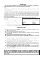
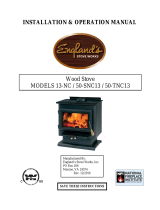
19
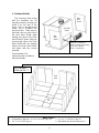
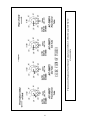
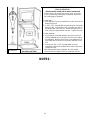
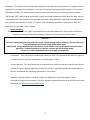
Placement of Stainless Steel Burner Tubes for all 30-NC, 50-SNC30 and 50-TNC30
stove models.

20
CREOSOTE
When wood is burned slowly, it produces tar and other organic vapors. These combine with moisture
to form creosote. Creosote vapors condense in the relatively cool chimney flue of a slow-burning fire
– as a result, creosote residue accumulates on the lining of the flue. If ignited, this creosote makes an
extremely hot fire. The chimney should be inspected on a regular basis during the heating season, to
determine if a creosote build-up has accumulated. If it has, the creosote should be removed to
reduce the risk of chimney fire.
WAYS TO PREVENT AND KEEP UNIT FREE OF CREOSOTE
1. Burn with the air control fully open for several minutes at numerous intervals throughout each
day during the heating season, being careful not to over-fire the unit. This should remove the
slight film of creosote that accumulates during low burn periods.
2. Burn the stove with the draft control fully open for approximately 20-30 minutes every time you
apply fresh wood. This allows wood to achieve the charcoal stage faster, and burns wood
vapors which might otherwise be deposited within the system.
3. BURN ONLY SEASONED WOOD. Avoid burning wet or green wood. Seasoned wood is
wood that has been dried for at least one year.
4. A small, hot fire is preferable to a large, smoldering one that can deposit creosote within the
system.
5. Establish a routine for fuel, wood burner and firing technique. Check daily for creosote build-
up until experience shows you how often you need to clean to be safe. Keep in mind that the
hotter the fire, the less creosote is deposited, and weekly cleanings may be necessary in
milder weather, although monthly cleanings may be enough in the coldest months. Contact
your local authority for information on how to handle a chimney fire, and have a clearly-
understood plan to handle a chimney fire.
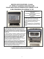
ASH DISPOSAL
Regularly inspect the ash build-up in your unit and remove as necessary. Ashes can be removed
from the unit by shoveling them off the firebrick. This unit has an ash drawer plate (see Illustration 4)
that can be removed from the stove; once removed, the ashes can be raked through the opening and
into the ash pan.
Caution: The ash drawer plate can be extremely hot!! Never remove red-hot ashes from the
appliance; allow ashes to cool before dropping into the ash pan. Ashes should be placed in a metal
container with an airtight lid. The ashes should be placed on a noncombustible surface and
completely away from any combustible materials. The ashes should remain in the airtight container
until they have completely cooled.
WARNING: THINGS TO REMEMBER IN CASE OF A CHIMNEY FIRE:
1. CLOSE DRAFT CONTROL 2. CALL THE FIRE DEPARTMENT
La page est en cours de chargement...
La page est en cours de chargement...
La page est en cours de chargement...
La page est en cours de chargement...
La page est en cours de chargement...
La page est en cours de chargement...
La page est en cours de chargement...
La page est en cours de chargement...
La page est en cours de chargement...
La page est en cours de chargement...
La page est en cours de chargement...
La page est en cours de chargement...
La page est en cours de chargement...
La page est en cours de chargement...
La page est en cours de chargement...
La page est en cours de chargement...
La page est en cours de chargement...
La page est en cours de chargement...
La page est en cours de chargement...
La page est en cours de chargement...
La page est en cours de chargement...
La page est en cours de chargement...
La page est en cours de chargement...
La page est en cours de chargement...
La page est en cours de chargement...
La page est en cours de chargement...
La page est en cours de chargement...
La page est en cours de chargement...
La page est en cours de chargement...
La page est en cours de chargement...
La page est en cours de chargement...
La page est en cours de chargement...
La page est en cours de chargement...
La page est en cours de chargement...
La page est en cours de chargement...
La page est en cours de chargement...
La page est en cours de chargement...
La page est en cours de chargement...
La page est en cours de chargement...
La page est en cours de chargement...
La page est en cours de chargement...
La page est en cours de chargement...
La page est en cours de chargement...
La page est en cours de chargement...
La page est en cours de chargement...
La page est en cours de chargement...
La page est en cours de chargement...
-
 1
1
-
 2
2
-
 3
3
-
 4
4
-
 5
5
-
 6
6
-
 7
7
-
 8
8
-
 9
9
-
 10
10
-
 11
11
-
 12
12
-
 13
13
-
 14
14
-
 15
15
-
 16
16
-
 17
17
-
 18
18
-
 19
19
-
 20
20
-
 21
21
-
 22
22
-
 23
23
-
 24
24
-
 25
25
-
 26
26
-
 27
27
-
 28
28
-
 29
29
-
 30
30
-
 31
31
-
 32
32
-
 33
33
-
 34
34
-
 35
35
-
 36
36
-
 37
37
-
 38
38
-
 39
39
-
 40
40
-
 41
41
-
 42
42
-
 43
43
-
 44
44
-
 45
45
-
 46
46
-
 47
47
-
 48
48
-
 49
49
-
 50
50
-
 51
51
-
 52
52
-
 53
53
-
 54
54
-
 55
55
-
 56
56
-
 57
57
-
 58
58
-
 59
59
-
 60
60
-
 61
61
-
 62
62
-
 63
63
-
 64
64
-
 65
65
-
 66
66
-
 67
67


Englander 30-NCH Manuel utilisateur
- Catégorie
- Poêle à bois
- Taper
- Manuel utilisateur
dans d''autres langues
- English: Englander 30-NCH User manual
Documents connexes


Autres documents
-
 Summers Heat 50-SNC13 Mode d'emploi
-
Vermont Castings WR244 Le manuel du propriétaire
-
 Summers Heat 50-SHSSW01LC Manuel utilisateur
-
 Summers Heat 50-SHW06L Manuel utilisateur
-
 Summers Heat 55-SHP10L Manuel utilisateur
-
 Summers Heat 55-SHPCAB80S Mode d'emploi
-
 Kichler Lighting 9549BKT Manuel utilisateur
-
HARVIA 20 BOILER Le manuel du propriétaire


