Transition Networks CSDTF30xx-11x Manuel utilisateur
- Catégorie
- Convertisseurs de média réseau
- Taper
- Manuel utilisateur

Installation . . . . . . . . . . . . . . . . . .2
Operation . . . . . . . . . . . . . . . . . . .6
Cable Specifications . . . . . . . . . . .7
Technical Specifications . . . . . . . .8
Troubleshooting . . . . . . . . . . . . . .9
Compliance Information . . . . . . .12
* Typical maximum cable distance. Actual
distance is dependent upon the physical
characteristics of the network.
CSDTF3027-115 75 ohm BNC coax
100 m (328 ft.)*
ST, 1300 nm multimode
5 km (3.1 miles)*
Part Number Port One - Copper Port Two - Duplex Fiber-Optic
CSDTF3011-115 75 ohm BNC coax
100 m (328 ft.)*
ST, 850 nm multimode
2 km (1.2 miles)*
CSDTF3012-115 75 ohm BNC coax
100 m (328 ft.)*
ST, 1310 nm single mode
8 km (4.8 miles)*
CSDTF3013-115 75 ohm BNC coax
100 m (328 ft.)*
SC, 850 nm multimode
2 km (1.2 miles)*
CSDTF3014-115 75 ohm BNC coax
100 m (328 ft.)*
SC, 1310 nm single mode
20 km (12.4 miles)*
CSDTF3015-115 75 ohm BNC coax
100 m (328 ft.)*
SC, 1310 nm single mode
40 km (24.8 miles)*
CSDTF3016-115 75 ohm BNC coax
100 m (328 ft.)*
SC, 1310 nm single mode
60 km (37.3 miles)*
CSDTF3017-115 75 ohm BNC coax
100 m (328 ft.)*
SC, 1550 nm single mode
80 km (49.7 miles)*
CSDTF3018-115 75 ohm BNC coax
100 m (328 ft.)*
MT-RJ, 1300 nm multimode
2 km (1.2 miles)*
CSDTF3022-115 75 ohm BNC coax
100 m (328 ft.)*
ST, 1310 nm single mode
15 km (9.3 miles)*
CSDTF3025-115 75 ohm BNC coax
100 m (328 ft.)*
MT-RJ, 1310 nm single mode
20 km (12.4 miles)*
User’s Guide
CSDTF30xx-11x
Slide-in-Module Media Converter
• E1 with Remote Management
• Coax (BNC) to Fiber
Transition Networks CSDTF30xx-11x series media
converter, designed to be installed into the Transition
Networks PointSystem™ chassis, encodes and decodes
E1 coax copper signals over fiber optic cable to extend
the distance and transmission reliability of high-speed E1
data traffic. The CSDTF30xx-11x is framing independent
(as ESF vs. D4) and supports all common line codes (e.g., AMI, B8ZS, HDB3).
The CSDTF30xx-11x is designed to be installed in pairs. For example, install one
CSDTF3011-115 as the local media converter and another CSDTF3011-115 as the
remote media converter.

224-hour Technical Support: 1-800-260-1312 -- International: 00-1-952-941-7600
CSDTF30xx-11x
* Typical maximum cable distance. Actual distance is dependent upon the
physical characteristics of the network. (TX) = transmit (RX) = receive
Part Number Port One - Copper Port 2 - Simplex Fiber Optic
CSDTF3029-115 and CSDTF3029-116 are intended to be
installed in the same link where one is the local converter and
the other is the remote converter.
CSDTF3029-117 and CSDTF3029-118 are intended to be
installed in the same link where one is the local converter and
the other is the remote converter.
CSDTF3029-115 75 ohm BNC coax
100 m (328 ft.)*
SC, 1310 mn (TX)/1550 nm (RX)
single mode, 20 km (12.4 miles)*
CSDTF3029-116 75 ohm BNC coax
100 m (328 ft.)*
SC, 1550 mn (TX)/1310 nm (RX)
single mode, 20 km (12.4 miles)*
CSDTF3029-117 75 ohm BNC coax
100 m (328 ft.)*
SC, 1310 mn (TX)/1550 nm (RX)
single mode, 40 km (24.8 miles)*
CSDTF3029-118 75 ohm BNC coax
100 m (328 ft.)*
SC, 1550 mn (TX)/1310 nm (RX)
single mode, 40 km (24.8 miles)*
Installation
CAUTION: Wear a grounding device and observe electrostatic discharge
precautions when setting the jumper. Failure to observe this caution could
result in damage to, and subsequent failure of, the media cverter.
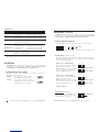
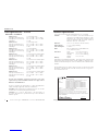
Set the Hardware/Software Jumper
The jumper is located on the circuit board. Use needle-nose pliers to move
the jumper to the desired position.
Hardware The media converter mode is
determined by the switch settings.
Software The media converter mode is
determined by the most-recently saved,
on-board microprocessor settings. Software Mode
Hardware Mode
HS
HS
E1 Configuration (switch 4)
IMPORTANT: Switch 4 MUST be set to
the “down” position to set the media
converter for E1 configuration.
E1 Configuration (down)
1342
IMPORTANT !
[email protected] -- Click the “Transition Now” link for a live Web chat. 3
Switch 2. Fiber -- Transmit All Ones
Up - Disables the Transmit All Ones
function on the fiber interface.
Down - Transmits an “all ones” pattern
on the fiber interface when the signal
detect on the coax interface is lost.
Switch 3. Not in use
Fiber - Transmit All Ones - Disabled
Fiber - Transmit All Ones - Enabled
1342
Installation -- Continued
CAUTION: Wear a grounding device and observe electrostatic discharge
precautions when setting the switches. Failure to observe this caution could
result in damage to, and subsequent failure of, the media converter.
Set the Configuration Switches
The configuration switches are located on the side of the media converter.
Use a small, flat-blade screwdriver or a similar device to set the recessed
switches.
Transmit All Ones (switches 1 & 2)
The Transmit All Ones function allows the insertion of an “all ones” pattern on
the interface when the signal detect is lost, creating an alarm condition at the
device connected to the interface.
Switch 1. Coax -- Transmit All Ones
Up - Disables the Transmit All Ones
function on the coax interface.
Down - Transmits an “all ones” pattern
on the coax interface when the signal
detect on the fiber interface is lost.
3412
Down Not UsedUp
key:
Coax - Transmit All Ones - Disabled
Coax - Transmit All Ones - Enabled
1342

424-hour Technical Support: 1-800-260-1312 -- International: 00-1-952-941-7600
CSDTF30xx-11x
Installation -- Continued
Set the Loop-Back Switch
Hardware Mode:
The loop-back switch is located on the front panel of the media converter and
is used for installation and network debugging procedures.
To set the switch, use a small flat-blade screwdriver or a
similar device (see the drawing to the right).
CL (Coax loop-back) Enable loop-back on the local coax interface.
-- (Center position) Normal operation.
FL (Fiber loop-back) Enable loop-back on the local fiber interface.
Software Mode:
If both media converters are under software control, the network administrator
can initiate the loop-back test function on the coax interface (local or remote)
or on the fiber interface (local or remote). These four loop-back test scenarios
are described in detail on page 11.
CL FL
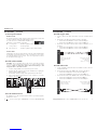
Install the Slide-in-Module
CAUTION: Wear a grounding device and observe electrostatic discharge
precautions when installing the CSDTF30xx-11x slide-in-module media
converter. Failure to observe this caution could result in damage to, and
subsequent failure of, the media converter.
1. Locate an emply installation slot in the PointSystem™ chassis
2. Carefully slide the slide-in-module into the installation slot, aligning the
module with the installation guides.
3. Ensure that the module is firmly seated against the back of the chassis.
4. Push in and rotate the panel fastener screw clockwise to secure the
module to the chassis front.
CFMFF100 CFMFF100
CETCF100 CFETF100
CFMFF100
SPD PWR
FRX
CRX
FLNK
CLNK
100BASE-TX
RX
TX
100BASE-FX
Link Alert
ED
050½
LA PWR
RXF
RXC
LNK
COL
LKS
PWR
LKM
10BASE-2
10BASE-FL
LKS
PWR
LKM
LKS
PWR
LKM
Multimode
Singlemode
TX
RX
TX
RX
Multimode
Singlemode
TX
RX
TX
RX
Multimode
Singlemode
TX
RX
TX
RX
I
0
TERM
INIT
RX
TX
LNK
PWR
CPSMM120
SERIAL
10BASE-T
R
E
S
E
T
I
0
Panel Fastener Screw
FLCL
SDC
RX
TX
Fiber
PWRSDF
RX
TX
Coax
Power the Media Converter
The CSDTF30xx-11x slide-in-module media converter is powered through the
PointSystem™ chassis.
[email protected] -- Click the “Transition Now” link for a live Web chat. 5
Installation -- Continued
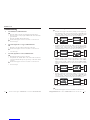
Install the Copper Cable
1. Locate or build coax cables with female connectors installed at both
ends.
2. Connect the coax cables to the media converter as described:
• Connect the female TX cable connector to the male TX port.
• Connect the female RX cable connector to the male RX port.
3. Connect the coax cables to the other device (switch, workstation, etc.) as
described:
• Connect the female TX cable connector to the male RX port.
• Connect the female RX cable connector to the male TX port.
Install the Fiber Cable
1. Locate or build fiber cable with male, two-stranded TX to RX connectors
installed at both ends.
2. Connect the fiber cables to the local media converter as described:
• Connect the male TX cable connector the female TX port.
• Connect the male RX cable connector to the female RX port.
3. Connect the fiber cables to the remote media converter as described:
• Connect the male TX cable connector the female RX port.
• Connect the male RX cable connector to the female TX port.
Connect the fiber cable
to the local media
converter as shown.
Connect the fiber cable
to the remote media
converter as shown
RX
TX
RX
TX
Connect the coax cable
to the media converter
as shown.
Connect the coax cable
to the other device
(switch, work
station, etc.) as shown
RX
TX
RX
TX

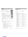
Operation
After installation, the media converter should function without
operator intervention. Use the status LEDs to monitor the media
converter operation in the network.
SDC (Signal Detect / Coax) On = The coax link is up.
SDF (Signal Detect / Fiber) On = The fiber link is up.
PWR (Power) On = The media converter is
connected to external power.
Remote Management
The CSDTF30xx-11x chassis media converter can remotely
manage the SSDTF30xx-11x, the stand-alone version of the
media converter.
For example, a local CSDTF3011-115 converter (that is
installed in a managed Transition Networks PointSystem™
chassis) is connected, via fiber, to a remote SSDTF3011-115
converter. An example of a managed single-fiber network
has a local CSDTF3029-115 converter connected, via fiber,
to a remote SDTF3029-116.
See the SNMP section (below) for a list of commands that
can be used to monitor and manage the CSDTF30xx-11x
and SSDTF30xx-11x converters.
NOTE: In a managed network, both the local and remote media converters
must be set to “software” mode (see page 2).
SNMP
See the on-line documentation that comes with Transition Networks
FocalPoint™ software for applicable commands and usage.
Use SNMP at an attached terminal or at a remote location to monitor the
media converter by monitoring:
• Media converter power
• Copper link and fiber link status (local and/or remote)
• AIS detected on copper link and fiber link (local and/or remote)
• Hardware switch settings
Also, use SNMP to enter network commands that:
• Bootload the firmware (local only)
• Enable/disable loopback on the copper link (local and/or remote)
• Enable/disable loopback on the fiber link (local and/or remote)
• Enable/disable Transmit All Ones on the fiber link when the copper
link is down (local and/or remote)
• Enable/disable Transmit All Ones on the copper link when the fiber
link is down (local and/or remote)
• Power-down the media converter
CSDTF30xx-11x
624-hour Technical Support: 1-800-260-1312 -- International: 00-1-952-941-7600
CSDTF115
FLCL
SDC PWRSDF
RX
TX
Fiber
RX
TX
Coax
[email protected] -- Click the “Transition Now” link for a live Web chat. 7
Fiber Cable
Single mode fiber (recommended): 9 µm
Multimode fiber (recommended): 62.5/125 µm
Multimode fiber (optional): 100/140, 85/140, 50/125 µm
CSDTF3011-115 850 nm multimode
Fiber Optic Transmitter Power: min: -14.0 dBm max: -12.0 dBm
Fiber Optic Receiver Sensitivity: min: -25.0 dBm max: -12.0 dBm
Link Budget: 11.0 dB
CSDTF3012-115 1310 nm single mode
Fiber-optic Transmitter Power: min: -27.0 dBm max: -10.0 dBm
Fiber-optic Receiver Sensitivity: min: -37.0 dBm max: -14.0 dBm
Link Budget: 10.0 dB
CSDTF3013-115 850 nm multimode
Fiber Optic Transmitter Power: min: -19.0 dBm max: -14.0 dBm
Fiber Optic Receiver Sensitivity: min: -32.5 dBm max: -14.0 dBm
Link Budget: 13.5 dB
CSDTF3014-115 1310 nm single mode
Fiber-optic Transmitter Power: min: -15.0 dBm max: -8.0 dBm
Fiber-optic Receiver Sensitivity: min: -31.0 dBm max: -8.0 dBm
Link Budget: 16.0 dB
CSDTF3015-115 1310 nm single mode
Fiber Optic Transmitter Power: min: -8.0 dBm max: -2.0 dBm
Fiber Optic Receiver Sensitivity: min: -38.0 dBm max: -8.0 dBm
Link Budget: 30.0 dB
CSDTF3016-115 1310 nm single mode
Fiber-optic Transmitter Power: min: -5.0 dBm max: 0.0 dBm
Fiber-optic Receiver Sensitivity: min: -38.0 dBm max: -8.0 dBm
Link Budget: 33.0 dB
CSDTF3017-115 1550 nm single mode
Fiber-optic Transmitter Power: min: -5.0 dBm max: 0.0 dBm
Fiber-optic Receiver Sensitivity: min: -34.0 dBm max: -7.0 dBm
Link Budget: 29.0 dB
CSDTF3018-115 1300 nm multimode
Fiber-optic Transmitter Power: min: -19.0 dBm max: -14.0 dBm
Fiber-optic Receiver Sensitivity: min: -33.5 dBm max: -14.0 dBm
Link Budget: 14.5 dB
Cable Specifications
Copper Cable
E1:
Cable Type: RG-59
Gauge: 24 to 22 AWG
Differential Characteristic Impedance: 75 ohm +/- 10%

824-hour Technical Support: 1-800-260-1312 -- International: 00-1-952-941-7600
CSDTF30xx-11x
Cable Specifications -- Continued
Fiber Cable -- Continued
CSDTF3022-115 1310 nm single mode
Fiber Optic Transmitter Power: min: -15.0 dBm max: -5.0 dBm
Fiber Optic Receiver Sensitivity: min: -25.0 dBm max: -14.0 dBm
Link Budget: 10.0 dB
CSDTF3025-115 1310 nm single mode
Fiber-optic Transmitter Power: min: -11.0 dBm max: -3.0 dBm
Fiber-optic Receiver Sensitivity: min: -20.0 dBm max: -3.0 dBm
Link Budget: 9.0 dB
CSDTF3027-115 1300 nm multimode
Fiber Optic Transmitter Power: min: -19.0 dBm max: -15.0 dBm
Fiber Optic Receiver Sensitivity: min: -32.5 dBm max: -14.0 dBm
Link Budget: 13.5 dB
CSDTF3029-115 1310 nm (TX)/1550 nm (RX) simplex
Fiber-optic Transmitter Power: min: -13.0 dBm max: -6.0 dBm
Fiber-optic Receiver Sensitivity: min: -32.0 dBm max: -3.0 dBm
Link Budget: 19.0 dB
CSDTF3029-116 1550 nm (TX /1310 nm (RX) simplex
Fiber-optic Transmitter Power: min: -13.0 dBm max: -6.0 dBm
Fiber-optic Receiver Sensitivity: min: -32.0 dBm max: -3.0 dBm
Link Budget: 19.0 dB
CSDTF3029-117 1310 nm (TX)/1550 nm (RX) simplex
Fiber-optic Transmitter Power: min: -8.0 dBm max: -3.0 dBm
Fiber-optic Receiver Sensitivity: min: -33.0 dBm max: -3.0 dBm
Link Budget: 25.0 dB
CSDTF3029-118 1550 nm (TX)/1310 nm (RX) simplex
Fiber-optic Transmitter Power: min: -8.0 dBm max: -3.0 dBm
Fiber-optic Receiver Sensitivity: min: -33.0 dBm max: -3.0 dBm
Link Budget: 25.0 dB
The fiber optic transmitters on this device meet Class I Laser safety
requirements per IEC-825/CDRH standards and comply with 21
CFR1040.10 and 21CFR1040.11.
Product is certified by the manufacturer to comply with DHHS Rule
21/CFR, Subchapter J applicable at the date of manufacture.
CAUTION: Visible and invisible laser radiation when open. Do not stare
into the beam or view directly with optical instruments.
CAUTION: Use of controls, adjustments or the performance of
procedures other than those specified herein may result in hazardous
radiation exposure.
[email protected] -- Click the “Transition Now” link for a live Web chat. 9
Technical Specifications
For use with Transition Networks Model CSDTF30xx-11x or equivalent
Standards Emissions: CISPR A; Telecordia TR-NWT-001089
(designed to meet; NOT tested); FCC Part 68; T1/E1
Physical layer: ITU-T, ANSI, AT&T, and ETSI; European
Technical Standard: TBR 12; British Technical
Publication: PD 7024 : 1994 (NTR 4)
Dimensions 3.4" x 5" x 0.87" (86 mm x 182 mm x 22 mm)
Shipping Weight 3 oz. (91 g) (approximately)
Power Consumption 3.7 Watts
MTBF 478,901 (MIL217F2 V5.0) (MIL-HDBD-217F)
1,333,687 (Bellcore7 V5.0)
Environment Tmra*: 0 to 50°C (32° to 122° F )
Storage Temp: -15° to 65°C (5° to 149°F)
Humidity: 5 to 95%, non condensing
Altitude: 0 to 10,000 feet
Warranty Lifetime
*Manufacturer’s rated ambient temperature. Tmra range for this slide-in-module
depends on the physical characteristics and the installation configuration of the
Transition Networks PointSystem™ chassis in which this slide-in-module will be
installed.
The information in this user’s guide is subject to change. For the most up-to-date
information on the CSDTF30xx-11x media converter, view the user’s guide on-
line at www.transition.com.
Declaration of Conformity
Name of Mfg: Transition Networks
6475 City West Parkway, Minneapolis MN 55344 USA
Model: CSDTF30xx-11x Series Media Converter
Part Number: CSDTF3011-115, CSDTF3012-115, CSDTF3013-115,
CSDTF3014-115, CSDTF3015-115, CSDTF3016-115,
CSDTF3017-115, CSDTF3018-115, CSDTF3022-115,
CSDTF3025-115, CSDTF3027-115, CSDTF3029-115,
CSDTF3029-116, CSDTF3029-117, CSDTF3029-118
Regulation: EMC Directive 89/336/EEC
Purpose: To declare that the CSDTF30xx-11x to which this declaration refers is
in conformity with the following standards.
CISPR 22:1993; EN 55022:1998+A1:2000 Class A; EN 55024:1998; FCC Part 15
Subpart B; EN 61000-3-2:1995+A14:2000: 61000-3-3:1995; CFR 21 Subpart J
I, the undersigned, hereby declare that the equipment specified above conforms to the above
Directive(s) and Standard(s).
August 8, 2002
Stephen Anderson, Vice-President of Engineering Date

10 24-hour Technical Support: 1-800-260-1312 -- International: 00-1-952-941-7600
CSDTF30xx-11x
Troubleshooting
1. Is the PWR (Power) LED illuminated?
NO
• Ensure the media converter is inserted properly into the chassis.`
• Ensure the power cord is properly installed in the chassis and in the
grounded outlet.
• Ensure the grounded outlet provides power.
• Contact Tech Support: 1-800-260-1312, Int’l: 00-1-952-941-7600.
YES
• Proceed to step 2.
2. Is the SDC (Signal Detect / Copper) LED illuminated?
NO
• Check the coax copper cables for the proper connection.
• Contact Tech Support: 1-800-260-1312, Int’l: 00-1-952-941-7600.
YES
• Proceed to step 3.
3. Is the SDF (Signal Detect / Fiber) LED illuminated?
NO
• Check the fiber cables for proper connection.
• Verify that the TX and RX cables on the local media converter are
connected to the RX and TX ports, respectively, on the remote media
converter.
• Contact Tech Support: 1-800-260-1312, Int’l: 00-1-952-941-7600.
YES
• Proceed to step 4.
[email protected] -- Click the “Transition Now” link for a live Web chat. 11
FiberCopper Copper
Local
Converter
w/ SNMP Management
Remote
Converter
Bit Error Test
Equipment
Remote
Device
FiberCopper Copper
Local
Converter
w/ SNMP Mana
g
ement
Remote
Converter
Bit Error Test
Equipment
Remote
Device
FiberCopper Copper
Local
Converter
w/ SNMP Management
Remote
Converter
Bit Error Test
Equipment
Remote
Device
FiberCopper Copper
Local
Converter
w/ SNMP Management
Remote
Converter
Bit Error Test
Equipment
Remote
Device
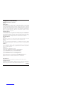
4. Is Data Transfer Failing?
YES
• Verify the local copper connection by starting a local copper loop-
back (hardware mode: set the loop-back switch on the local media
converter to “CL”, software mode: enter the local copper loop-back
command) and then use a bit error test unit to run a bit error test.
• Verify the local fiber connection by starting a remote fiber loop-back
(hardware mode: set the loop-back switch on the remote media
converter to “FL”, software mode: enter the remote fiber loop-back
command) and then use a bit error test unit to run a bit error test.
• Verify the remote copper connection by starting a remote copper
loop-back (hardware mode: set the loop-back switch on the remote
media converter to “CL”, software mode: enter the remote copper
loop-back command) and then use a bit error test unit to run a bit
error test.
• Verify the remote fiber connection by starting a local copper loop-
back (hardware mode: set the loop-back switch on the local media
converter to “FL”, software mode: enter the local fiber loop-back
command) and then use a bit error test unit to run a bit error test.
• Contact Tech Support: 1-800-260-1312, Int’l: 00-1-952-941-7600.
NO
• Contact Tech Support: 1-800-260-1312, Int’l: 00-1-952-941-7600.

Trademark Notice
All trademarks and registered trademarks are the property of their respective owners.
Copyright Restrictions
© 2002-2004 Transition Networks. All rights reserved. No part of this work may be
reproduced or used in any form or by any means - graphic, electronic, or mechanical -
without written permission from Transition Networks. Printed in the U.S.A.
33247.D
Compliance Information
CISPR22/EN55022 Class A + EN55024
CE Mark
FCC Regulations
This equipment has been tested and found to comply with the limits for a Class A digital
device, pursuant to part 15 of the FCC rules. These limits are designed to provide reasonable
protection against harmful interference when the equipment is operated in a commercial
environment. This equipment generates, uses, and can radiate radio frequency energy and, if
not installed and used in accordance with the instruction manual, may cause harmful
interference to radio communications. Operation of this equipment in a residential area is
likely to cause harmful interference, in which case the user will be required to correct the
interference at the user's own expense.
Canadian Regulations
This digital apparatus does not exceed the Class A limits for radio noise for digital apparatus
set out on the radio interference regulations of the Canadian Department of Communications.
Le présent appareil numérique n'émet pas de bruits radioélectriques dépassant les limites
applicables aux appareils numériques de la Class A prescrites dans le Règlement sur le
brouillage radioélectrique édicté par le ministère des Communications du Canada.
European Regulations
Warning
This is a Class A product. In a domestic environment this product may cause radio
interference in which case the user may be required to take adequate measures.
Achtung !
Dieses ist ein Gerät der Funkstörgrenzwertklasse A. In Wohnbereichen können bei Betrieb
dieses Gerätes Rundfunkstörungen. In diesem Fäll ist der Benutzer für Gegenmaßnahmen
verantwortlich.
Attention !
Ceci est un produit de Classe A. Dans un environment domestique, ce produit risque de
créer des interférences radioélectriques, il appartiendra alors à l'utilsateur de prende les
measures spécifiques appropriées.
Contact Us:
Technical support is available 24 hours a day.
US and Canada: 1-800-260-1312 International: 00-1-952-941-7600
Chat live via the Web with Transition Networks Technical Support.
Log onto www.transition.com and click the Transition Now link.
Transition Networks provides seminars via live web-based training.
Log onto www.transition.com and click the Learning Center link.
Send an e-mail anytime to our technical support staff: [email protected]
Transition Networks, 6475 City West Pkwy, Minneapolis, MN 55344, USA
telephone: 952-941-7600 -- toll free: 800-526-9267 -- fax: 952-941-2322
-
 1
1
-
 2
2
-
 3
3
-
 4
4
-
 5
5
-
 6
6
-
 7
7


Transition Networks CSDTF30xx-11x Manuel utilisateur
- Catégorie
- Convertisseurs de média réseau
- Taper
- Manuel utilisateur
dans d''autres langues
Documents connexes
-
Transition Networks J/E-CF-02 Manuel utilisateur
-
-
-
Transition Networks TN-CWDM-SFP-1290 Manuel utilisateur
-
-
-
Transition Networks Switch CERTXFX01(SM) Manuel utilisateur