Tesy ELECTRIC WATER HEATER Mode d'emploi
- Taper
- Mode d'emploi

BG 3-5
Инструкция за употреба и поддръжка
EN ELECTRIC WATER HEATER 6-8
Instructions for use and maintenance
RU
9-11
Инструкция по употреблению обслужванию
ES
TERMO DE AGUA ELÉCTRICO 12-14
Instrucciones de uso y mantenimiento
PT CALENTADOR DE AQUA ELÉCTRICO 15-17
Manual de instalação e uso
DE
ELEKTRISCHER WARMWASSERSPEICHER 18-20
Gebrauchsanleitung und pege
RO
BOILER ELECTRIC 21-23
Instrucțiuni de utilizare și întreinținere
PL
ELEKTRYCZNY PODGRZEWACZ WODY
24-26
Instrukcja instalacji, użytkowania i obsługi
CZ ELEKTRICKÝ OHŘÍVAČ VODY 27-29
Návod k použití a údržbě
RS
ELEKTRIČNI BOJLER 30-32
Uputstvi za upotrebu i održavanje
HR
ELEKTRIČNE GRIJALICE VODE 33-35
Upute za uporabu i održavanje
UA
36-38
Керівництво з установки й експлуатації
GR ΗΛΕΚΤΡΙΚO ΘΕΡΜΟΣΙΦΝΟ 39-41
Οδηγίες χρήσεις και συντήρησης
MK
42-44
Инструкции за употреба и одржување
FR
CHAUFFEEAU ÉLECTRIQUE
45-47
Instruction d’installation et de fonctionnement


Инструкция за употреба и поддръжка 3
BG
Български
I.
1. Настоящото техническо описание и инструкция за експлоатация има за цел да Ви запознае с изделиeтo и условията за неговото правилно монтиране и
експлоатация. Инструкцията е предназначена и за правоспособните техници, които ще монтират първоначално уреда, демонтират и ремонтират в случай на
повреда.
2. Спазването на указанията в настоящата инструкция е преди всичко в интерес на купувача. Заедно с това е и едно от гаранционните условия, посочени в
гаранционната карта, за да може купувачът да ползва безплатно гаранционно обслужване. Производителят не отговаря за повреди в уреда, причинени в
резултат на експлоатация и/или монтаж, които не съответстват на указанията и инструкциите в това ръководство.
3. Електрическият бойлер отговаря на изискванията на EN 60335-1, EN 60335-2-21.
4. Този уред е предназначен да бъде използван от деца на 8 и над 8 годишна възраст и хора с намалени физически, чувствителни или умствени
способности, или хора с липса на опит и познания, ако са под нaблюдение или инструктирани в съответствие с безопасната употребата на уреда
и разбират опасностите които могат да възникнат.
5. Децата не трябва да си играят с уреда.
6. Почистването и обскужването на уреда не трябва да се извършва от деца които не са под надзор.
ВНИМАНИЕ! Неправилният монтаж и свързване на уреда може да го направи опасен за здравето и живота на потребителите,
като е възможно да нанесе тежки и трайни последствия за тях, включително но не само физически увреждания и/или
смърт. Това също може да доведе до щети за имуществото им /увреждане и/или унищожаване/, както и на това на трети лица,
причинени включително но не само от наводняване, взрив и пожар.
Монтажът, свързването към водопроводната и електрическата мрежа, и въвеждането в експлоатация следва да бъдат извършвани
само и единствено от правоспособни електротехници и техници за ремонт и монтаж на уреда, придобили своята правоспособност
на територията на държавата, на която се извършват монтажът и въвеждането в експлоатация на уреда и в съответствие с
нормативната и уредба.
Забраняват се всякакви промени и преустройства в конструкцията и електрическата схема на бойлера. При
констатиране на такива гаранцията за уреда отпада. Като промени и преустройства се разбира всяко премахване
на вложени от производителя елементи, вграждане на допълнителни компоненти в бойлера, замяна на елементи с аналогични
неодобрени от производителя.
------------------------------------------------------------------------------------------------------------------------------------------------------------------------------------------------------------------------------------
------------------------------------------------------------------------------------------------------------------------------------------------------------------------------------------------------------------------------------
1. Електрическият бойлер
да се монтира само в помещения с нормална пожарна обезопасеност.
2. При монтаж в баня той трябва да бъде монтиран на такова място, че да не бъде обливан с вода от душ или душ-слушалка.
3. Електрическият бойлер е предназначен за експлоатация само в закрити и отопляеми помещения, в които температурата не пада под 4°C и не е предназначен
да работи в непрекъснато проточен режим.
4. При монтаж към стена - уредът се окачва за носещaтa планкa монтиранa към корпуса му. Окачването става на две куки (min. Ø 10 mm) закрепени надеждно
към стената (не са включени в комплекта за окачване).
------------------------------------------------------------------------------------------------------------------------------------------------------------------------------------------------------------------------------------
------------------------------------------------------------------------------------------------------------------------------------------------------------------------------------------------------------------------------------
1. Уредът е предназначен да обезпечава с гореща вода битови обекти, имащи водопроводна мрежа с налягане не повече от 6 bars (0.6 MPa).
2. - , . Той се поставя на входа за студена вода, в съответствие
със стрелката на корпуса му, която указва посоката на входящата вода.
: Ако местните регулации (норми) изискват използването на друг предпазен клапан или устройство (отговарящ на EN 1487 или EN 1489),
то той трябва да бъде закупен допълнително. За устройства отговарящи на EN 1487 максималното обявено работно налягане трябва да бъде 0.7 MPa. За
други предпазни клапани, налягането на което са калибрирани трябва да бъде с 0.1 MPa под маркираното на табелката на уреда. В тези случаи възвратно
предпазния клапан доставен с уреда не трябва да се използва.
3. Възвратно-предпазният клапан и тръбопровода от него към бойлера трябва да бъдат защитени от замръзване. При дрениране с маркуч –
свободният му край трябва винаги да е отворен към атмосферата (да не е потопен). Маркуча също трябва да е осигурен срещу замръзване.
4. За безопасната работа на бойлера, възвратно-предпазния клапан редовно да се почиства и преглежда дали функционира нормално /да
не е блокиран/, като за районите със силно варовита вода да се почиства от натрупания варовик. Тази услуга не е предмет на гаранционното
обслужване.
5. За избягване причиняването на вреди на потребителя и на трети лица в случаи на неизправност в системата за снабдяване с топла вода е
необходимо уреда да се монтира в помещения имащи подова хидроизолация и дренаж в канализацията. В никакъв случаи не слагайте под уреда
предмети, които не са водоустойчиви. При монтиране на уреда в помещения без подова хидроизолация е необходимо да се направи защитна вана
под него с дренаж към канализацията
6. При експлоатация (режим на нагряване на водата), е нормално да капе вода от отвора за източване на предпазния клапан. Същият трябва
да бъде оставен открит към атмосферата. Трябва да бъдат взети предварителни мерки за отвеждане или събиране на изтеклото количество за
избягване на щети.
7. При вероятност температурата в помещението да спадне под 0°С, бойлерът трябва да се източи.
Когато се налага и е задължително първо да прекъснете електрическото захранване към него. Спрете подаването на вода към уреда.
Отворете крана за топла вода на смесителната батерия. Отворете крана 7 (фиг. 4) за да източите водата от бойлера. Ако в инсталацията не е инсталиран такъв,
бойлерът може да бъде източен директно от входящата му тръба, като предварително бъде разкачен от водопровода
.
------------------------------------------------------------------------------------------------------------------------------------------------------------------------------------------------------------------------------------
------------------------------------------------------------------------------------------------------------------------------------------------------------------------------------------------------------------------------------
1. Не включвайте бойлера без да сте се убедили, че е пълен с вода.
2. При свързване на бойлера към електрическата мрежа да се внимава за правилното свързване на защитния проводник (при модели без шнур
с щепсел).
3. При модели, които нямат монтиран захранващ шнур с щепсел, в електрическия контур за захранване на уреда трябва да бъде вградено
устройство което осигурява разединяване на всички полюси в условията на свръхнапрежение категория III.
4. Ако захранващия шнур (при моделите окомплектовани с такъв) е повреден той трябва да бъде заменен от сервизен представител или лице
с подобна квалификация за да се избегне всякакъв риск.
5. При бойлерите за хоризонтален монтаж, изолацията на захранващите проводници от електрическата инсталация трябва да бъдe защитенa
от допир с фланеца на уреда (в зоната под пластмасовия капак). Примерно с изолационен шлаух с температурна устойчивост по-голяма от 90°C.
6. По време на загряване от уреда може да има шум от свистене (завираща вода). Това е нормално и не индикира повреда. Шумът се засилва с
времето и причината е натрупания варовик.
,
TESY . , .

4 Инструкция за употреба и поддръжка
BG II.
1. Номинална вместимост, литри - виж табелката върху уреда
2. Номинално напрежение - виж табелката върху уреда
3. Номинална мощност - виж табелката върху уреда
4. Номинално налягане - виж табелката върху уреда
Това не е водопроводно налягане. То е обявено за уреда и се
отнася до изискванията на стандартите за безопасност.
5. Тип на бойлера - затворен акумулиращ водонагревател, с
топлоизолация
6. Дневно потребление на електроенергия - виж Приложение I
7. Обявен товарен профил - виж Приложение I
8. Количеството на смесена вода при 40°C V40 в литри - виж Приложение I
9. Максимална температура на термостата - виж Приложение I
10. Фабрично зададени температурни настройки - виж Приложение I
11. Енергийна ефективност при подгряване на водата - виж Приложение I
III.
Уредът се състои от корпус, фланец в долната си част /при
бойлери за вертикален монтаж/ или в страни /при бойлери
за хоризонтален монтаж/, предпазен пластмасов панел и
възвратно-предпазен клапан.
1. Корпусът се състои от стоманен рeзервоар
(водосъдържател) и кожух (външна обвивка) с топлоизолация
между тях от екологично чист високоплътен пенополиуретан, и
две тръби с резба G ½ “ за подаване на студена вода (със син
пръстен) и изпускане на топла (с червен пръстен).
Вътрешния резервоар в зависимост от модела може да бъде
два вида:
•От черна стомана защитена със специално стъкло-
керамично или емайлово покритие
•От неръждаема стомана
2. На фланеца е монтиран електрически нагревател. При
бойлерите със стъкло-керамично покритие е монтиран и
магнезиев протектор.
Електрическият нагревател служи за нагряване на водата в
резервоара и се управлява от термостата, който автоматично
поддържа определена температурата.
Уредът разполага с вградено устройство за защита от
прегряване (термоизключвател), което изключва нагревателя
от електрическата мрежа, когато температурата на водата
достигне твърде високи стойности.
3. Възвратно-предпазният клапан предотвратява пълното
изпразване на уреда при спиране на подаването на студена
вода от водопроводната мрежа. Той защитава уреда от
повишаване на налягането във водосъдържателя до стойност
по-висока от допустимата при режим на загряване ( ! при
повишаване на температурата водата се разширява и
налягането се повишава), чрез изпускане на излишъка през
дренажния отвор.
Възвратно-предпазният клапан не може да защити
уреда при подавано от водопровода налягане по-
високо от обявеното за уреда. Подаването на по-високо от
обявеното в тази инструкция водопроводно налягане към
уреда може да го увреди, при което гаранцията му отпада
и производителят не носи отговорност за евентуални
причинени щети.
IV.
ВНИМАНИЕ! Неправилният монтаж и свързване на
уреда може да го направи опасен за здравето и
живота на потребителите, като е възможно да нанесе
тежки и трайни последствия за тях, включително но не
само физически увреждания и/или смърт. Това също може
да доведе до щети за имуществото им /увреждане и/или
унищожаване/, както и на това на трети лица, причинени
включително но не само от наводняване, взрив и пожар.
Монтажът, свързването към водопроводната и
електрическата мрежа, и въвеждането в експлоатация
следва да бъдат извършвани само и единствено от
правоспособни електротехници и техници за ремонт и
монтаж на уреда, придобили своята правоспособност на
територията на държавата, на която се извършват
монтажът и въвеждането в експлоатация на уреда и в
съответствие с нормативната и уредба.
1.
ВАЖНО:
Инсталирането на уреда е за сметка на купувача.
Препоръчва се монтирането на уреда да е максимално близко
Препоръчва се монтирането на уреда да е максимално близко
до местата за използване на топла вода, за да се намалят
топлинните загуби в тръбопровода. При монтаж в баня той
трябва да бъде монтиран на такова място, че да не бъде
обливан с вода от душ или душ-слушалка.
•вертикален монтаж GCV (фиг. 1a, таблица 1) -
При монтаж към
стена - уредът се окачва за носещaтa планкa монтиранa
към корпуса му. Окачването става на две куки (min. Ø 10
mm) закрепени надеждно към стената (не са включени в
комплекта за окачване). Конструкцията на носещата планка,
при бойлери за вертикален монтаж е универсална и позволява
разстоянието между куките да бъде от 220 до 310 мм - фиг. 1a.
•хоризонтален монтаж - GCH и GCVHL модели (фиг.1b, 1c ) - При
хоризонтален монтаж разстоянията между куките са различни за
различните обеми и са посочени в таблица 2 - фиг.1b и таблица
3 - фиг.1c
.
За избягване причиняването на вреди на потребителя и на
трети лица в случаи на неизправност в системата за
снабдяване с топла вода е необходимо уреда да се монтира в
помещения имащи подова хидроизолация и дренаж в канализацията.
В никакъв случаи не слагайте под уреда предмети, които не са
водоустойчиви. При монтиране на уреда в помещения без подова
хидроизолация е необходимо да се направи защитна вана под него
с дренаж към канализацията.
Забележка: защитната вана не влиза в комплекта и се
избира/закупува от потребителя.
Производителят не носи отговорност за евентуални щети при
неспазване на условията, описани по-горе.
2.
Фиг.4: a - за вертикален; b - хоризонтален монтаж;
Където: 1-Входяща тръба; 2 – предпазен клапан; 3-редуцир
вентил (при налягане във водопровода над 0.6 MPa); 4-
спирателен кран; 5 – фуния с връзка към канализацията;
6-маркуч; 7 – кран за източване на бойлера
При свързването на бойлера към водопроводната мрежа трябва
да се имат предвид указателните цветни знаци /пръстени/ на
тръбите: син - за студена /входящата/ вода, червен - за гореща
/изходящата/ вода.
Той се поставя на входа за студена вода, в съответствие със
стрелката на корпуса му, която указва посоката на входящата
вода.
Изключение: Ако местните регулации (норми) изискват
използването на друг предпазен клапан или устройство
(отговарящ на EN 1487 или EN 1489), то той трябва да бъде
закупен допълнително. За устройства отговарящи на EN 1487
максималното обявено работно налягане трябва да бъде
0.7 MPa. За други предпазни клапани, налягането на което
са калибрирани трябва да бъде с 0.1 MPa под маркираното
на табелката на уреда. В тези случаи възвратно предпазния
клапан доставен с уреда не трябва да се използва.
Не се допуска друга спирателна арматура между възвратно-
предпазния клапан (предпазното устройство) и уреда.
Наличието на други (стари) възвратно-предпазни клапани
може да доведе до повреда на вашия уред и те трябва да се
премахнат.
Не се допуска навиването на клапана към резби с дължина над
10 мм., в противен случай това може да доведе до повредата
на вашия клапан, което е опасно за вашия уред.
При бойлерите за вертикален монтаж предпазният клапан
трябва да бъде свързан към входящата тръба при свален
пластмасов панел на уреда.
Възвратно-предпазният клапан и тръбопровода от него към
бойлера трябва да бъдат защитени от замръзване. При
дрениране с маркуч – свободният му край трябва винаги да е
отворен към атмосферата (да не е потопен). Маркуча също трябва
да е осигурен срещу замръзване.
За да напълните уреда с вода, първо отворете само крана за
топла вода на смесителната батерия след него. След това
отворете крана за студена вода преди него. Уредът е напълнен,
когато от смесителната батерия потече непрекъсната струя
вода. Затворете крана за топла вода.
Когато се налага изпразване на бойлера е задължително първо
да прекъснете електрическото захранване към него. Спрете
подаването на вода към уреда. Отворете крана за топла вода на
смесителната батерия. Отворете крана 7 (фиг. 4) за да източите
водата от бойлера. Ако в инсталацията не е инсталиран такъв,
бойлерът може да бъде източен бойлерът може да бъде източен
директно от входящата му тръба, като предварително бъде
разкачен от водопровода
При свалянето на фланеца е нормално да изтекат няколко
литра вода останали във водосъдържателя.
При източване трябва да се вземат мерки за
предотвратяване на щети от изтичащата вода.
В случай, че налягането във водопроводната мрежа надвишава
посочената стоност в параграф I по-горе, то е необходимо
да се монтира редуцир вентил, в противен случай бойлера
няма да бъде експлоатиран правилно. Производителят не
поема отговорност за произтеклите проблеми от неправилна
експлоатация на уреда.
3.
Преди да включите електрическото захранване, уверете се че
уреда е пълен с вода.

Инструкция за употреба и поддръжка 5
BG
Български
3.1. При моделите снабдени със захранващ шнур в комплект
с щепсел свързването става, като той бъде включен в
контакт. Разединяването от електрическата мрежа става, като
изключите щепсела от контакта.
Контакт трябва да бъде правилно свързан към отделен токов
кръг осигурен с предпазител. Той трябва да бъде заземен.
3.2. Водонагреватели окомплектовани със захранващ шнур
без щепсел
Уредът трябва да бъде свързан към отделен токов кръг
от стационарната електрическата инсталация, осигурен с
предпазител с обявен номинален ток 16А (20A за мощност >
3700W). Свързването трябва да е постоянно – без щепселни
съединения. Токовият кръг трябва да бъде осигурен с предпазител
и с вградено устройство, което осигурява разединяване на всички
полюси в условията на свръхнапрежение категория III.
Свързването на проводниците на захранващия шнур на уреда
трябва да бъде изпълнено както следва:
•Проводник с кафяв цвят на изолацията – към фазовия
проводник от електрическата инсталация (L)
•Проводник със син цвят на изолацията – към неутралния
проводник от електрическата инсталация (N)
•Проводник със жълто-зелен цвят на изолацията – към
защитния проводник от електрическата инсталация ( )
3.3. При модели, които нямат монтиран захранващ шнур с
щепсел.
Уредът трябва да бъде свързан към отделен токов кръг
от стационарната електрическата инсталация, осигурен с
предпазител с обявен номинален ток 16А (20A за мощност
> 3700W). Свързването се осъществява с медни едножилни
(твърди) проводници - кабел 3 x 2,5 mm2 за обща мощност
3000W (кабел 3 x 4.0 mm2 за мощност > 3700W).
В електрическия контур за захранване на уреда трябва да
бъде вградено устройство което осигурява разединяване на
всички полюси в условията на свръхнапрежение категория III.
За да се монтира захранващия електрически проводник към
бойлера е необходимо да се свали пластмасовия капак
Свързването на захранващите проводници трябва да е в
съответствие с маркировките на клемите, както следва:
•фазовия към означение A или А1 или L или L1
•неутралния към означение N (B или B1 или N1)
•Задължително е свързването на защитният проводник към
винтовото съединение, означено със знак .
След монтаж, пластмасовият капак се поставя отново!
Пояснение към фиг.3:
TS – термоизключвател; TR – терморегулатор; S – ключ (при
моделите с такъв); R – нагревател; IL – сигнална лампа; F –
фланец.
V.
Магнезиевият аноден протектор допълнително защитава
вътрешната повърхност на водосъдържателя от корозия. Той е
износващ се елемент, който подлежи на периодична подмяна,
която е за сметка на потребителя.
С оглед на дългосрочната и безаварийна експлоатация на
Вашия бойлер производителят препоръчва периодичен преглед
на състоянието на магнезиевия анод от правоспособен техник
и подмяна при необходимост, като това може да стане по време
на периодичната профилактика на уреда. За извършване
на подмяната се обърнете към оторизиран сервиз или
правоспособен техник!
VI.
.
1.
1.1.
Фиг. 2 където:
1 - Бутон на електрически ключ (при модели с ключ)
2 - Светлинни индикатори
3 - Ръкохватка за терморегулатор (интегрирана с бутона на
електрическия ключ)
1.2. .
Включването на бойлера се осъществява посредством
устройството вградено в инсталацията, описанo в подточка
3.3 от параграф V или свързване на щепсела с електрически
контакта (ако модела е с шнур с щепсел).
: Моделите са с вграден в бойлера ключ и е
необходимо да включите и него.
Посредством бутона на електрическия ключ се управлява
режима на включване/изключване на захранването към
нагревателя.
Бутонът на електрическия ключ на уреда е означен с знак
.
Той е релефен.
За да включите електрическият ключ натиснете бутона до упор
и отпуснете. Бутонът остава натиснат, което означава, че е
включен. Светлинните индикатори също светват.
За да изключите електрическия ключ натиснете бутона до
упор, след което го отпуснете. Бутонът трябва да изпъкне,
което означава, че е изключен. Светлинните индикатори също
изгасват.
“ON”
“OFF”
Контролни лампи (индикатори)
Светят в червен цвят – уредът е в режим на загряване на
водата;
Светят в син цвят – водата в уреда е загрята и терморегулатора
е изключил захранването на нагревателя.
Индикаторите не светят, когато:
електрическият ключ на уреда е изключен, или
няма подадено електрическо захранване към уреда, или
температурната защита на уреда е изключила – виж т.2 по-долу.
1.3.
Тази функция дава възможност за избор на желаната
температура. За да направите своя избор завъртете
ръкохватката от панела, като поставите маркера в съответната
позиция (фиг.2). За повишаване на температурата завъртете в
посока на часовниковата стрелка.
Веднъж месечно поставяйте ръкохватката на позиция за
максимална температура, за период от едно денонощие (освен
ако уреда работи постоянно в този режим), виж Приложение-I -
Максимална температура на термостата. Така се осигурява по-висока
хигиена на загряваната вода.
•
Поставете ръкохватката на позиция „MIN“ съгласно фиг.2.
При тази настройка уреда поддържа температура която не
позволява водата в него да замръзне.
ВАЖНО: Електрическото захранване на уреда трябва да бъде
включено. Вграденият в бойлера ключ също трябва да е
включен. Предпазния клапан и тръбопровода от него към уреда
задължително трябва да са осигурени срещу замръзване
• ПЕСТЕНЕ НА ЕЛЕКТРОЕНЕРГИЯ – При този
режим температурата на водата достига до около 60°С. По този
начин се намаляват топлинните загуби.
2.
Уредът е оборудван със специално устройство
(термоизключвател) за защита от прегряване на водата,
което изключва нагревателя от електрическата мрежа, когато
температурата достигне твърде високи стойности.
След задействане това устройство не се самовъзстановява и
уредът няма да работи. Обърнете се към оторизиран сервиз за
отстраняване на проблема.
VII.
При нормална работа на бойлера, под въздействието на
високата температура на повърхността на нагревателя се
отлага варовик /т.н.котлен камък/. Това влошава топлообмена
между нагревателя и водата. Температурата на повърхността
на нагревателя и в зоната около него се повишава. Появява
се характерен шум /на завираща вода/. Терморегулатора
започва да включва и изключва по-често. Възможно е
“лъжливо” задействане на температурната защита. Поради
това производителят на този уред препоръчва профилактика
на всеки две години на Вашият бойлер от оторизиран
сервизен център или сервизна база, като услугата е за
сметка на клиента. Тази профилактика трябва да включва
почистване и преглед на анодния протектор (при бойлери със
стъклокерамично покритие), който при необходимост да се
замени с нов.
За да почистите уреда използвайте влажна кърпа. Не
използвайте абразивни или съдържащи разтворител
почистващи вещества.
Старите електроуреди съдържат ценни материали
и поради това не трябва да се изхвърлят заедно с
битовата смет! Молим Ви да съдействате с активния
си принос за опазване на ресурсите и околната
среда и да предоставите уреда в организираните
изкупвателни пунктове(ако има такива).

6 Instructions for use and maintenance
EN I. IMPORTANT RULES
1. This technical description and instructions manual was prepared in order to acquaint you with the product and the conditions of proper installation and
use. These instructions were also intended for use by qualied technicians, who shall perform the initial installation, or disassembly and repairs in the event of a
breakdown.
2. Following the current instructions will primarily be of interest to the consumer, but along with this, it is also one of the warranty conditions, pointed out in the
warranty card, so that the consumer can benet from the free warranty services. The producer is not responsible for damages in the appliance that have appeared
as a result of operation and/or installation not corresponding to the instructions here.
3. The electric water heater complies with the requirements of
EN 60335-1, EN 60335-2-21.
4. This appliance can be used by children aged from 8 years and above and persons with reduced physical, sensory or mental capabilities or lack of experience and
knowledge if they have been given supervision or instruction concerning use of the appliance in a safe way and understand the hazards involved.
5. Children shall not play with the appliance.
6. Cleaning and user maintenance shall not be made by children without supervision.
Attention! Improper installation and connection of the appliance may make it hazardous for the health and life of consumers. It may
cause grievous and permanent consequences, including but not limited to physical injuries and/or death. Improper installation and
connection of the appliance may also lead to damage to the consumers’ property /damage and/ or destruction/, or to that of third persons,
as a result of, but not limited to ooding, explosion and/or re.
Installation, connection to the main water and power supply, and putting into operation must be carried out by certied electricians and technical
personnel certied in installation of this category of appliances, who have obtained their license in the state where the installation and commissioning
of the appliance are carried out, and in compliance with its local legislation.
All alterations and modications to the water heater’s construction and electrical circuitry are forbidden. If such alterations or modications are established
during inspection, the appliance’s warranty shall be null and void. Alterations and modications shall mean each instances of removal of elements incorporated
by the manufacturer, building in of additional components into the water heater, replacement of elements by similar elements unapproved by the manufacturer.
-----------------------------------------------------------------------------------------------------------------------------------------------------------------------------------------------------------------------------
Mounting
----------------------------------------------------------------------------------------------------------------------------------------------------------------------------------------------------------------------------
1. The water heater must only be mounted in premises with normal re resistance
.
2. In the event the device is mounted in a bathroom, the selected location must exclude the possibility of water spray contact from the showerhead or portable
showerhead attachment.
3. The water heater is designed to operate only in closed and heated premises where the temperature is not lower than 4°C and it is not designed to operate in a
continuous protracted regime.
4. The appliance is axed to a wall via the mounting brackets attached to the unit’s body (if the brackets are not attached to the unit’s body, they must be axed in
place via the provided bolts).
-----------------------------------------------------------------------------------------------------------------------------------------------------------------------------------------------------------------------------
Water heater connection
-----------------------------------------------------------------------------------------------------------------------------------------------------------------------------------------------------------------------------
1. The appliance is intended to supply hot water to household sites equipped with a piping system working at pressure below 6 bar (0,6 Mpa).
2. .
The safety return-valve must be mounted on the cold water supply pipe, in observance of the direction arrow stamped on its body, indicating the incoming
water’s direction. Additional stopcocks must not be mounted between the safety return-valve and the water heater.
Exception: If the local regulations (norms) require the usage of another protection valve or mechanism (in accordance with EN 1487 or EN 1489), then it must be
bought additionally. For mechanisms operating in accordance with EN 1487 the announced operational pressure must be no more than 0.7 MPa. For other protection
valves, the pressure at which they are calibrated must be 0.1 MPa lower than the one marked on the appliance’s sign. In these cases the safety valve which the appliance
is supplied with should not be used.
3. The safety valve and the pipe between the valve and the water heater must be protected from freezing. During hose draining - its free end must be always open
to the atmosphere (not to be immersed). Make sure that the hose is also protected from freezing.
4. In order to secure the water heater’s safe operation, the safety return-valve must undergo regular cleaning and inspections for normal functioning /the valve
must not be obstructed/, and for the regions with highly calcareous water it must be cleaned from the accumulated lime scale. This service is not provided under
warranty maintenance
.
5. In order to prevent injury to user and third persons in the event of faults in the system for providing hot water, the appliance must be mounted in premises
outtted with oor hydro insulation and plumbing drainage. Don’t place objects, which are not waterproof under the appliance under any circumstances. In
the event of mounting the appliance in premises not outtted with oor hydro insulation, a protective tub with a plumbing drainage must be placed under the
appliance.
6. During operation – regime of heating the water – water drops through the drainage opening of the protection valve are usual.
The protection valve should be left
open to the atmosphere. Measures should be taken to lead and collect the leakages in order to prevent damages.
7. If the probability exists for the premise’s temperature to fall below 0°С, the water heater must be drained.
In the event you must empty the water heater, rst you must cut o its power supply. The inow of water from the water mains must rst be terminated and the hot
water tap of the mixing-faucet must be opened. The water tap 7 (g 4) must be opened to drain the water from water tank. If there is no such tap build in the pipe
line, than the water can be drain directly from inlet pipe of water tank after when you disconnect it from water main.
-----------------------------------------------------------------------------------------------------------------------------------------------------------------------------------------------------------------------------
Connection to the electrical network
-----------------------------------------------------------------------------------------------------------------------------------------------------------------------------------------------------------------------------
1. Do not switch on the water heater unless you established it was lled with water.
.
2. Upon connecting the water heater to the electric mains care must be taken to connect the safety lead
.
3. Models without power cord
,
the circuit has to be supplied with a safety fuse (16A) and with inbuilt device to ensure disconnection of all pole pieces in the
conditions of over-voltage from category III
.
4. If the power supply cord (of models that have one) is damaged, it must be replaced by a service representative or a person with similar qualication, to avoid any
risk
.
5. For water heaters intended for horizontal mounting
t
he power supply conductor insulation from xed wiring must be protected from direct contact with
the ange (in zone under the plastic panel). For example, insulating sleeving having temperature rating higher than 90 °C can be used
.
6. During the heating the appliance could produce a hissing noise (the boiling water). This is common and does not indicate any damage. The noise gets higher with
the time and the reason for this is the accumulation of limestone. To remove the noise the appliance must be cleaned from limestone. This type of cleaning is not
covered by the warranty
.
Dear Clients,
The TESY team would like to congratulate you on your new purchase. We hope that your new appliance shall bring more comfort to your home.

Instructions for use and maintenance 7
EN
English
II.
1. Nominal volume V, liters - see the appliance’s rating plate
2. Nominal voltage - see the appliance’s rating plate
3. Nominal power consumption - see the appliance’s rating plate
4. Nominal pressure - see the appliance’s rating plate
This is not the water mains pressure. This is the pressure that is
announced for the appliance and refers to the requirements of the
safety standards.
5. Water heater type - closed type accumulating water heater, with thermal
insulation
6. Daily energy consumption – see Annex I
7. Rated load prole - see Annex I
8. Quantity of mixed water at 40°C V40 litres - see Annex I
9. Maximum temperature of the thermostat - see Annex I
10. Default temperature settings - see Annex I
11. Energy eciency during water heating - see Annex I
III.
The appliance consists of a body, ange at the bottom side /for
water heaters intended for vertical mounting/ or at the sides /for
water heaters intended for horizontal mounting/, protective plastic
panel safety-return valve.
1. The body consists of a steel reservoir (water tank) and housing
(outer shell) with thermal insulation placed in-between made of
ecologically clean high density polyurethane foam, and two pipes
with thread G ½ ‘’ for cold water supply (marked by a blue ring) and
hot water outlet pipe (marked by a red ring).
The inner tank may be of two types depending on the model:
•Made of steel protected form corrosion by a special glass-
ceramics coating
•Made of stainless steel
2. The ange is outtted with: electric heater and thermostat.
The water heaters with glass-ceramics coating are outtted with a
magnesium protector.
The electric heater is used for heating the water in the tank and is
managed by the thermostat, which automatically maintains the set
temperature.
The thermostat has a built in overheating safety device, which
switches of power to the heater when the water temperature
reaches excessive values.
3. The safety-return valve prevents the appliance’s complete
emptying in the event the cold water supply is interrupted. The
valve protects the appliance from pressure increases higher than
the allowed value during heating (! pressure increases upon an
increase of temperature), via release of excess pressure during the
drainage opening.
The safety-return valve cannot protect the appliance in the event of
water mains pressure in excess of the acceptable pressure stated
for the appliance.
IV.
Attention! Improper installation and connection of the
appliance may make it hazardous for the health and life of
consumers. It may cause grievous and permanent consequences,
including but not limited to physical injuries and/or death. Improper
installation and connection of the appliance may also lead to
damage to the consumers’ property /damage and/ or destruction/,
or to that of third persons, as a result of, but not limited to ooding,
explosion and/or re. Installation, connection to the main water and
power supply, and putting into operation must be carried out by
certied electricians and technical personnel certied in installation
of this category of appliances, who have obtained their license in
the state where the installation and commissioning of the appliance
are carried out, and in compliance with its local legislation.
Notice: The installation of the unit is at the buyer’s expense.
1.
We recommend the mounting of the device at close proximity to
locations where hot water is used, in order to reduce heat losses
during transportation. In the event the device is mounted in a
bathroom, the selected location must exclude the possibility of
water spray contact from the showerhead or portable showerhead
attachment.
• (g. 1a, table 1) –
The appliance is axed to
a wall via the mounting brackets attached to the unit’s body (if the
brackets are not attached to the unit’s body, they must be axed in
place via the provided bolts). Two hooks are used for suspending
the appliance (min. Ø 10 mm) set rmly in the wall (not included in
the mounting set). The mounting bracket’s construction designed for
water heaters intended for vertical mounting is universal and allows a
distance between the hooks of 220 to 310 mm (g. 1a).
models (g.1b, 1c) – At horizontal
installation the distances between the carrying hooks are dierent with the
dierent capacities and these values are indicated in table 2 - g.1b and table
3 - g. 1c
.
In order to prevent injury to user and third persons in the event of
faults in the system for providing hot water, the appliance must be
mounted in premises outtted with oor hydro insulation and plumbing
drainage. Don’t place objects, which are not waterproof under the appliance
under any circumstances. In the event of mounting the appliance in
premises not outtted with oor hydro insulation, a protective tub with a
plumbing drainage must be placed under the appliance.
Notice: the set does not include a protective tub and the user
must select the same.
2.
Fig. 4:
Where: 1 - Inlet pipe; 2 - Safety valve; 3 - reducing valve (for water
main pressure > 0,6 MPa); 4 - Stop valve; 5 - Funnel connected to
the sewer network; 6 – Hose; 7 - Drain water tap.
Upon connecting the water heater to the water mains you must
consider the indicative color markings /rings/ axed to the pipes:
blue for cold /incoming/ water, red for hot /outgoing/ water.
The mounting of the safety return-valve supplied with the water
heater is obligatory. The safety return-valve must be mounted on
the cold water supply pipe, in observance of the direction arrow
stamped on its body, indicating the incoming water’s direction.
Additional stopcocks must not be mounted between the safety
return-valve and the water heater.
Exception: If the local regulations (norms) require the usage
of another protection valve or mechanism (in accordance with
EN 1487 or EN 1489), then it must be bought additionally. For
mechanisms operating in accordance with EN 1487 the announced
operational pressure must be no more than 0.7 MPa. For other
protection valves, the pressure at which they are calibrated must
be 0.1 MPa lower than the one marked on the appliance’s sign. In
these cases the safety valve which the appliance is supplied with
should not be used.
The presence of other /old/ safety return-valves may lead to a
breakdown of your appliance and they must be removed.
Other type of stopping armature is not allowed between the protection
return valve (the protective device) and the appliance.
The attaching of the safety return-valve to threads longer than 10 mm is not
allowed, otherwise this may damage the valve and poses danger for your
appliance.
With appliances for vertical assembly, the safety valve has to be
connected to the ingoing pipe with the safety plastic panel of the
appliance being taken o.
The safety valve and the pipe between the valve and the water heater
must be protected from freezing. During hose draining - its free end must
be always open to the atmosphere (not to be immersed). Make sure that the hose
is also protected from freezing.
Opening the cold-water stopcock of the water supply piping network
and opening the hot-water stopcock of the water-mixing faucet
carries out the lling of the water heater with water. After the lling is
complete, a constant stream of water must begin to ow from the
water-mixing faucet. Now you can close the hot water stopcock.
In the event you must empty the water heater, rst you must cut o
its power supply. The inow of water from the water mains must rst
be terminated and the hot water tap of the mixing-faucet must be
opened. The water tap 7 (g 3) must be opened to drain the water
from water tank. If there is no such tap build in the pipe line, than
the water can be drain directly from inlet pipe of water tank after
when you disconnect it from water main
In the event of removing the ange, the discharge of several liters of
water, which remain in the water tank, is normal.
Measures must be undertaken to prevent damage from discharging
water during draining
In case that the pressure in the water mains is over the value
pointed out in the above paragraph I, then it is necessary to
assemble a pressure reduce valve, otherwise the water heater
would not function properly. The Manufacturer does not assume any
liability for problems arising out of the appliance’s improper use.
3.
Make sure the appliance is full of water prior to switching on the
electrical mains power.
3.1. Models with power cord with a plug are connected by
inserting the plug into a contact. They are switched o the power
supply by drawing the plug out of the contact.

8 Instructions for use and maintenance
EN
The wall-plug must be properly connected to a separate electrical
circle that is provided with a protector. It must be earthed.
3.2. The appliance has to be connected to a separate electricity
circuit of the stationary electrical wiring. The connecting has
to be constant- with no plug contacts. The circuit has to be
supplied with a safety fuse (16A) and with inbuilt device to ensure
disconnection of all pole pieces in the conditions of over-voltage
from category III.
The connecting of the conductors of the supply cord of the
appliance has to be carried out as follows:
•conductor with brown insulation – to the phase conductor of the
electrical wiring (L)
•conductor with blue insulation- to the neutral conductor of the
wiring (N)
•conductor with yellow-green insulation – to the safety conductor
of the wiring ( )
3.3. Models without power cord
The appliance has to be connected to a separate electricity circuit
of the stationary electrical wiring. The circuit has to be supplied with
a safety fuse 16A (20A for power > 3700W). Copper single core
(rigid – non stranded) conductor shall be used for the connection –
cable 3 x 2.5 mm² (cable 3 x 2.5 mm² for power > 3700W).
The electrical circuit supplying the appliance must have an in-built
device ensuring the splitting of all terminal poles under conditions of
super-voltage of category III.
To install the power supply wire to the appliances remove the plastic
cover.
Connect the power wires in compliance with the marks on the
terminals, as follows:
•the phase - to mark A, A1, L or L1;
•the neutral - to N (B or B1 or N1)
•The safety wire must be obligatory connected to the screw joint
marked with .
After the installation, put the plastic cover back in its place!
Explanations to Fig. 3:
TS - thermal switch; TR - thermal regulator; S - switch (for models
that have one); R - heater; IL - light indicator; F - ange.
V.
The magnesium anode protects the water tank’s inner surface from
corrosion.
The anode element is an element undergoing wear and tear and is
subject to periodic replacement.
In view of the long-term and accident free use of your water
heater, the manufacturer recommends periodic inspections of
the magnesium anode’s condition by a qualied technician and
replacement whenever required, and this could be performed during
the appliance’s technical preventive maintenance.
For replacements, please contact the authorized service stations!
VI.
Before switching on the appliance for rst time, make sure that the
water heater is properly connected to the power supply network and
full with water.
1.
1.1. Control Elements
Fig. 2 where:
1 - Key of a power switch (on key models)
2 – luminous indicators
3 - Handle for thermoregulator (integrated with the key of the power
switch).
1.2. Switching on the appliance .
The boiler is switched on by means of the appliance incorporated in
the installation described in
subsection 3 of paragraph V or by connecting the plug to the
electrical socket (if the model is with a cord with a plug).
: The models have a built-in switch in the boiler and
you need to turn it on as well. The power switch button of the
appliance is embossed and is marked
.
The switching on-o mode of the power to the heater is controlled
by the power switch button.
To turn the power switch on, press the button until it stops and then
release it. The button remains pressed, which means it is on. The
light indicators also light up.
To turn o the power switch, press the button until it stops and then
release it. The button must stand out, which means it is o. The
light indicators also go out.
“ON”
“OFF”
Control lights (indicators)
Illuminated in red color - the appliance is in heating water mode;
Illuminated in blue color - the water in the appliance is heated and
the thermostat switches o the heater‘s power.
Indicators do not illuminate when:
the electrical switch of the appliance is switched o, or
no electrical power is supplied to the appliance, or
the temperature protection of the appliance has been switched o -
see section 2 below.
1.3. Setting the temperature
This function allows you to select the desired temperature. To make
your choice, turn the handle on the panel by placing the marker in
the appropriate position (Fig. 2). To increase the temperature, turn
clockwise.
Place the thermostat knob in position for maximum
temperature (unless it is on this position constantly), for
period of one day each month - see Annex-I Maximum
temperature of the thermostat. This ensures higher hygiene of the
used hot water.
•
Set the handle to the „MIN“ position according to gure 2. With this
setting, the appliance maintains a temperature that prevents the
water from freezing.
The power supply of the appliance must be switched on.
The safety valve and the pipeline from it to the appliance
compulsory must be secured against frost.
• e
At this mode, water temperature reaches up to approximately 60°С.
Heat losses are reduced in this way.
2.
The appliance is equipped with a special facility (thermal circuit-
breaker) for protection against over-heating of the water, which
is switching o the heater from the electricity network, when the
temperature reaches too high values.
When this device operates, it does not self-reset and the
appliance will not work. Please call an authorized service for
solving the problem.
VII.
Under normal use of the heater, under the inuence of high
temperature, lime scale /the so-called lime scale layer/ is deposited
upon the heating element’s surface. This worsens the heat
exchange between the heating element and water. The heating
element’s surface temperature increases along /of boiling water/.
The thermoregulator begins to switch on and o more frequently. A
‘’deceptive” activation of the thermal protection is possible. Due to
these facts, the manufacturer recommends preventive maintenance
of your water heater every two years by an authorized service
center or service base. This protective maintenance must include
cleaning and inspection of the anode protector (for water heaters
with glass-ceramic coating), which shall be replace with a new one
if need arises.
In order to clean the appliances use a damp cloth. Do not clean with
abrasive or solvent content detergents. Do not pour water over the
appliance.
Old electric appliances contain precious materials and
thus should not be thrown together with the household
litter. We kindly ask you make your active contribution for
protecting the resources and the environment by handing
over the appliance in the authorized buy-back stations (if
such exist).

Инструкция по эксплуатации обслуживанию 9Русский
RU
I.
1. Настоящая инструкция ознакомит Вас с изделием и условиями его правильного монтажа и эксплуатации. Инструкция предназначена также
для технических специалистов, которые будут выполнять первоначальный монтаж устройства, его демонтаж и ремонт в случае неполадок.
Соблюдение настоящей инструкции необходимо в интересах покупателя, а также является одним из условий, указанных в гарантии.
2. Прошу вас, имейте ввиду, что соблюдение указаний в настоящей инструкции прежде всего в интересе покупателя, но вместе с этим одно из
условий гарантий, указанных в карте гарантии, чтобы покупатель мог бы пользовать бесплатно гарантийное обслуживание. Производитель не
несет ответственость для увреждений прибора и возможных увреждений, причиненных в результате эксплуатации и/или установки, которые
не соответствуют на указания и инструкции в этом руководстве.
3. Электрический бойлер отвечает требованиям EN 60335-1, EN 60335-2-21.
4. Этот прибор предназначен быть использован детьми 8-ми и больше 8-ми летнего возраста и людьми с ограниченными физическими,
чувствительными или умственными способностями, или людьми с отсутствием опыта и познаний, если они под нaблюдением или их
инструктировали в соответствии с безопасным употреблением прибора и они понимают опасности, которые могли бы возникнуть.
5. Детям нельзя играть с прибором
6. Уборка и обслуживание прибора нельзя быть выполнена детьми, которые не контролируются.
ВНИМАНИЕ! Неправильная установка и подключение прибора могут сделать его опасным для здоровья и жизни
потребителей, а также может причинить серьезные и долговечные последствия для них, в том числе, но не только, к
физическим повреждениям и/или смерти. Это также может привести к ущербам их имущества /повреждению и/или
уничтожению/, а также таким третьих лиц, вызванным включительно, но не только, наводнением, взрывом, пожаром.
Монтаж, подключение к водопроводу и к электрической сети должны выполняться правоспособными электротехниками и техниками по
ремонту и монтажу приборов, которые получили свою правоспособность на территории страны, в которой осуществляется монтаж и
ввод в эксплуатацию прибора и в соответствии с нормами ее законодательства.
Любые изменения и переустройства в конструкции и электрической схеме бойлера запрещены. При их констатации гарантия
теряет свое действие. Под изменениями и переустройством подразумевается любое удаление заводских элементов, установка
в бойлере дополнительных компонентов, замена элементов аналогичными, но не одобренными производителем.
------------------------------------------------------------------------------------------------------------------------------------------------------------------------------------------------------------------------------------
------------------------------------------------------------------------------------------------------------------------------------------------------------------------------------------------------------------------------------
1. Бойлер следует устанавливать только в помещениях с нормальной пожарной безопасностью.
2. При монтаже в ванной комнате бойлер устанавливается в таком месте, куда не попадает вода из душа или душевого распылителя.
3. Бойлер предназначен для эксплуатации только в закрытых и отапливаемых помещениях, в которых температура не падает под 4°C и не
предназначен работать в непрерывном проточном режиме.
4. Бойлер монтируется с помощью планки прикрепленной к его корпусу (если она не закреплена, это следует выполнить с помощью
прилагаемых болтов).
------------------------------------------------------------------------------------------------------------------------------------------------------------------------------------------------------------------------------------
------------------------------------------------------------------------------------------------------------------------------------------------------------------------------------------------------------------------------------
1. Устройство предназначено для обеспечения горячей водой бытовых объектов, а также водопроводной сети с давлением не более 6 атм.
(0,6 Mpa).
2. Монтаж возвратно-предохранительного клапана, прилагаемого к бойлеру, является обязательным. Он монтируется на входе для
холодной воды, в соответствии с расположением стрелки на его корпусе, указывающей направление входящей воды. Не допускается
наличие другой останавливающей арматуры между клапаном и устройством.
: Если местные регуляции (нормы) требуют использование другого предохранительного клапана или устройства (отвечающее на
EN 1487 или EN 1489), его нужно купить дополнительно. Для устройств, отвечающих на EN 1487 максимальное объявленное рабочее давление
должно быть 0.7 MPa. Для других предохранительных клапанов, чье давление калиброванное, должно быть 0.1 MPa ниже указанного на
табличке прибора. В этих случаях нельзя использовать возвратно предохранительного клапана, который входит в комплекте поставки.
3. Возвратно предохранительный клапан и трубопровод от него к водонагревателю должны быть защищенными от замораживания. При
дренированием с шлангом – его свободный конец должен всегда быть открытым к атмосфере (Не погруженный). Шланг тоже должен быть
обеспечен против замораживания.
4. Для безопасной работы бойлера необходимо регулярно проверять работу (на предмет блокирования) и очищать возвратно-
предохранительный клапан, а в районах с жесткой водой очищать его от накипи. Эта услуга не входит в гарантийное обслуживание.
5. В целях безопасности потребителя и третьих лиц в случае неполадок в системе подачи горячей воды необходимо устанавливать
бойлер в помещениях, имеющих напольную гидроизоляцию и канализационный дренаж. Запрещается устанавливать бойлер на
неводоустойчивые предметы. При монтаже устройства в помещениях без напольной гидроизоляции необходимо под бойлером
установить защитную ванну с канализационным дренажом
6. При эксплуатации – (режим нагревания воды) – нормально капать вода из дренажного отверстия клапана. Тот же можно оставить
открытым к атмосфере. Надо принять меры для удаления или сбора оттока во избежания ущербов.
7. Если есть вероянтость, что температура в помещении понижится ниже 0°С, из бойлера нужно вылеть воду.
Если необходимо слить из бойлера воду, прежде всего, необходимо выключить его из электросети. Остановите подачу воды к прибору.
Откройте кран для теплой воды смесительной батерии. Откройте кран 7 (фиг. 4) для того, чтобы вытекла вода из бойлера. Если в установке
он не монтирован, то из бойлера можно вылеть воду прямо из входяшей из него трубы, которая предварительно может быть демонтиран
от водопровода.
------------------------------------------------------------------------------------------------------------------------------------------------------------------------------------------------------------------------------------
------------------------------------------------------------------------------------------------------------------------------------------------------------------------------------------------------------------------------------
1. Не включайте бойлер не убедившись, что он наполнен водой.
2. При подключении бойлера в электрическую сеть необходимо обратить внимание на правильное подключение защитного проводник.
3. В моделях без шнуром питания, В электрический контур питания должно быть установлено устройство, обеспечивающее разъединение
всех полюсов в условиях сверхнапряжения категории III.
4. Если шнур питания (в моделях, оснащенных таковым) поврежден, он должен быть заменен представителем сервиса или лицом с подобной
квалификацией во избежание любого риска.
5. У бойлеров для горизонтального монтажа изоляция провода электпитания рической инсталяции, должна защищать от прикосновения
с фланцом устройства (в зоне под пластиковой крышкой). Например при помощи изоляционной трубы с температурной устойчивостью
больше 90°C.
6. Во время нагревания прибор можете услышать свистящий шум (вода кипятит). Это нормально и не является неисправностью. Шум усиливаетсь
со времени и из-за накопления известняка. Чтобы устранить шум, необходимо почистить прибор. Эта услуга не покрывается гарантией.
,
TESY . , .

10 Инструкция по употреблению обслужванию
RU
II.
1. Номинальный объем V, литры см. табличку на приборе
2. Номинальное напряжение - см. табличку на приборе
3. Номинальная мощность - см. табличку на приборе
4. Номинальное давление - см. табличку на приборе
Это не давление водопроводной сети. Номинальное давление
относится к прибору и соответствует требованиям
стандартов безопасности.
5. Тип водонагревателя - закрытый накопительный
водонагреватель, с теплоизоляцией
6. Ежедневное потребление электроэнергии – см. Приложение I
7. Объявленный профиль нагрузки- см. Приложение I
8. Количество смешанной воды при 40°C V40 в литрах – см.
Приложение I
9. Максимальная температура термостата – см. Приложение I
10. Заводские настройки температуры – см. Приложение I
11. Энергоэффективность в режиме нагрева воды – см.
Приложение I
III.
Устройство состоит из корпуса, фланца в нижней части / у
водонагревателей, предназначенных для вертикальной установки
/ или в боковой части / у водонагревателей, предназначенных для
горизонтальной установки /, предохранительной пластмассовой панели
и предохранительного клапана.
1. Корпус состоит из стального резервуара (внутреннего бака) и кожуха
(внешняя обшивка) с теплоизоляцией между ними из экологического
чистого пенополиуретана высокой плотности, и двух патрубков с
резьбой G ½ - для подачи холодной воды (с синим кольцом) и для
выхода горячей воды (с красным кольцом).
Внутренний бак в зависимости от модели может быть двух видов:
•Из черной стали, защищенной специальным стеклокерамическим
антикоррозийным покрытием
•Из нержавеющей стали
2. На фланце устанавливаются нагревательный элемент и термостат.
В водонагреватели с внутренним баком со стеклокерамическим
покрытием устанавливается также и магниевый анод. Нагревательный
элемент служит для нагревания воды во внутреннем баке и управляется
термостатом, который автоматически поддерживает определенную
температуру.
Термостат снабжен встроенным устройством защиты от перегрева
(термовыключатель), которое выключает нагревательный элемент, когда
температура воды превышает допустимое значение.
3. Предохранительный клапан предотвращает утечку воды
из водонагревателя при остановке подачи холодной воды из
водопроводной сети. Он защищает устройство от повышения давления
во внутреннем баке свыше установленного в режиме нагрева (! при
повышении температуры вода расширяется) путем выпуска излишков
воды через дренажное отверстие
Предохранительный клапан не может защитить прибор в
случае подачи воды из водопроводной сети под давлением,
превышающим давление, разрешенное для безопасной эксплуатации
прибора.
IV.
ВНИМАНИЕ! Неправильная установка и подключение прибора
могут сделать его опасным для здоровья и жизни
потребителей, привести к серьезным и необратимым
последствиям, в том числе, к физическим повреждениям и/или
смерти. Неправильная установка и подключение прибора может
привести к повреждению и/или уничтожению имущества как
потребителей, так и третьих лиц, в частности, к затоплению,
взрыву, пожару. Монтаж, подключение к водопроводу и к
электрической сети должны выполняться квалифицированными
специалистами по монтажу и ремонту приборов, которые получили
свою квалификацию на территории страны, в которой
осуществляется монтаж и ввод в эксплуатацию прибора и в
соответствии с ее нормами .
Примечание: Установка прибора производится за счет покупателя.
1.
Водонагреватель рекомендуется устанавливать в максимальной
близости к месту использования горячей воды, чтобы сократить потери
тепла воды в трубопроводе. В ванной комнате водонагреватель
устанавливается в таком месте, куда не попадает вода из душа.
Водонагреватель устанавливается с помощью планки, прикрепленной к
его корпусу (если она не закреплена, это следует выполнить с помощью
креплений в комплекте водонагревателя). Установка осуществляется
с помощью двух крючков (мин. Ø 10 мм), прочно закрепленных
на стене (не входят в комплект). Конструкция несущей планки у
водонагревателей, предназначенных для вертикальной установки
универсальна, и позволяет установить расстояние между крючками
от 220 до 310 мм (рис.1а). У водонагревателей, предназначенных для
горизонтальной установки расстояние между крючками различные для
различных моделей, и указаны в таблице 2 (рис. 1c).
В целях безопасности потребителя и третьих лиц в случае
неполадок в системе водоснабжения необходимо
устанавливать водонагреватель в помещениях, имеющих напольную
гидроизоляцию и канализационный дренаж. Запрещается
устанавливать водонагреватель над предметами, не имеющими
защиты от воздействия воды. При установке прибора в помещениях
без напольной гидроизоляции необходимо под водонагревателем
установить защитную ванну с канализационным дренажом.
Примечание: защитная ванна не входит в комплект
водонагревателя.
2.
Рис. 4
Где: 1 - Входная труба; 2 - предохранительный клапан; 3 –
редукционный клапан (при давлении в водопроводе выше 0,7 МПа);
4 – запорный клапан; 5 – воронка, подсоединенная к канализационной
системе; 6 – шланг; 7 – кран для слива воды из водонагревателя.
При подключении водонагревателя к водопроводной сети
необходимо обратить внимание на кольца патрубков: синее
- для холодной / поступающей/ воды, красное для горячей /
выходящей/ воды.
Установка предохранительного клапана, входящего в комплект
водонагревателя, является обязательной. Предохранительный
клапан устанавливается на входящем патрубке / для холодной
воды, в соответствии с расположением стрелки на его корпусе,
указывающей направление потока воды.
Не допускается установка запорной арматуры между клапаном
и устройством. Исключение: если местные законодательные или
технические нормы требуют использование другого предохранительного
клапана или устройства (отвечающее требованиям стандартов EN 1487
или EN 1489), его необходимо приобрести дополнительно. Для устройств,
отвечающих требованиям стандартов EN 1487 максимальное заявленное
рабочее давление должно быть 0.7 МПа. Для других предохранительных
клапанов заявленное рабочее давление должно быть на 0.1 МПа ниже
указанного на табличке прибора. В этих случаях нельзя использовать
предохранительный клапан, который входит в комплект водонагревателя.
Наличие установленного стороннего /старого/
предохранительного клапана может привести к
повреждению водонагревателя, поэтому он должен быть
заменен.
Не допускается установка запорной арматуры между
предохранительным клапаном и прибором.
Не допускается закручивание клапана на резьбу длиной более 10 мм,
это может привести к повреждению клапана и поломке
водонагревателя.
Предохранительный клапан и патрубок, на котором он установлен
должны быть защищенными от замерзания.
При использовании дренажного шланга – его свободный конец не должен
погружаться в воду. Шланг должен быть защищен от замерзания.
Для заполнения водонагревателя водой необходимо открыть кран
подачи холодной воды из водопроводной сети и кран для горячей воды
смесителя. После наполнения водонагревателя водой из смесителя
потечет постоянная струя воды, после чего можно закрыть кран для
горячей воды смесителя.
Если необходимо слить из водонагревателя воду, прежде всего,
необходимо отключить его от электросети. Остановите подачу воды
к прибору. Откройте кран для горячей воды смесителя. Откройте
кран 7 (рис. 4) для того, чтобы слить воду из водонагревателя. Если в
установке он не монтирован, то из бойлера мажно вылеть воду прямо
из входяшей из него трубы, которая предварительно может быть
демонтиран от водопровода.
При снятии фланца обычно вытекает несколько литров воды,
оставшейся во внутреннем баке.
При сливе воды необходимо предпринять меры предосторожности
во избежание причинения ущерба и повреждений.
В случае, если давление в водопроводной сети превышает указанное
в параграфе I значение, то необходимо установить редукционный
клапан, в противном случае производителем не гарантируется
правильная работоспособность водонагревателя. Производитель
не несет ответственность за проблемы, связанные с неправильной
эксплуатацией прибора.
3. Подключение к электрической сети
Перед подключением водонагревателя к электрической сети
необходимо убедиться, что он заполнен водой.
3.1. Водонагреватель, оснащенный кабелем питания с вилкой,
подключается к электрической сети путем включения вилки в розетку.

Инструкция по эксплуатации обслуживанию 11Русский
RU
Отсоединение от электрической сети происходит выключением вилки
из розетки.
Розетка должна быть правильно подключена к электрической сети и
защищена автоматическим выключателем. Розетка должна быть
заземлена
3.2. Водонагреватель, оснащенный кабелем питания без вилки,
должен подключаться к отдельной цепи электрической сети,
защищенной автоматическим выключателем с заявленным
номинальным током 16А (20A для мощности более 3700 Вт).
Соединение должно быть неразрывным – без штепсельных
соединений. Автоматический выключатель должен обеспечивать
разъединение всех полюсов в условиях перенапряжения категории III.
Подключение проводов кабеля питания прибора должно происходить по
следующей схеме:
•Провод коричневого цвета – к проводу фазы электрической сети (L)
•Провод синего цвета – к проводу нуля электрической сети (N)
•Провод желто-зеленого цвета – к проводу заземления электрической
сети ( )
3.3.
подключаться к отдельной цепи электрической сети,
защищенной автоматическим выключателем с заявленным
номинальным током 16А (20A для мощности более 3700 Вт).
Соединение осуществляется медным проводом с одной жилой
(силовой кабель 3x2,5 мм² для общей мощности 3000Вт
(кабель 3x4.0 мм² для общей мощности более 3700Вт).).
Автоматический выключатель должен обеспечивать разъединение
всех полюсов в условиях перенапряжения категории III.
Для подсоединения кабеля питания к водонагревателю
необходимо снять пластмассовую крышку.
Подсоединение проводов должно быть в соответствии с
маркировками электрических зажимов:
•Провод фазы к обозначению A или А1 или L или L1
•Провод нуля к обозначению B или B1 или N1
•Провод заземления подсоединить к винтовому соединению,
обозначенному знаком .
После монтажа, пластмассовая крышка устанавливается на
место!
Пояснение к рис.3:
TS – термовыключатель; TR – терморегулятор; S –
выключатель (при моделях с таковым); R – нагревательный
элемент; IL – световой индикатор; F – фланец.
V.
Магниевый анод защищает внутреннюю поверхность
внутреннего бака от коррозии.
Это расходный элемент, который подлежит периодической
замене. В целях долгосрочной и безаварийной эксплуатации
вашего водонагревателя производитель рекомендует
периодически осуществлять проверку состояния магниевого
анода квалифицированным техническим специалистом и
осуществлять замену в случае необходимости. Замена может
проводиться и во время периодической профилактики прибора.
VI.
Перед первоначальным включением прибора убедитесь в том, что он
включен правильно в электрическую сеть и наполнен водой.
1.
1.1. Элементы управления
Рис. 2, где:
1 - Кнопка электрического выключателя (у моделей с
выключателем)
2 - Световые индикаторы
3 - Рукоятка для терморегулятора (встроена с кнопкой
электрического выключателя).
1.2. Включение устройства
Включение бойлера осуществляется посредством
переключателя, встроенного в установку, описанного в
подпункте 3.3 пункта V или связыванием штепселя с контактом
(если модель с шнуром с штепселем).
Примечание: При моделей с встроенным в бойлере
переключателем необходимо включить и его. Кнопка
электрического переключателя прибора означена знаком .
Она релефная.
Режим включения / выключения питания нагревателя
контролируется электрическим выключателем.
•Чтобы включить электрический выключатель, нажмите
кнопку до упора и отпустите ее. Кнопка остается нажатой, что
означает, что она включена. Светодиоды также загораются.
•Чтобы выключить электрический выключатель, нажмите
кнопку до упора, затем отпустите. Кнопка должна выделяться,
что означает, что она выключена. Светодиоды тоже гаснут.
“ON”
“OFF”
Контрольные лампы (индикаторы)
Светятся в красным цветом – прибор в режиме нагревания
воды
Светятся в синим цветом – вода в приборе нагрета и
терморегулятор выключился
Индикаторы не светятся, когда:
•электрический переключатель прибора выключен, или
•нет приложенного электрического питания прибора или
•температурная защита прибора выключилась – посмотри т. 2
ниже.
1.3.
Эта функция позволяет выбрать желаемую температуру. Чтобы
сделать свой выбор, поверните ручку на панели, поместив
маркер в соответствующее положение (рис.2). Чтобы увеличить
температуру, поверните ручку по часовой стрелке.
Раз в месяц устанавливайте ручку в положение максимальной
температуры на один день (если прибор не работает непрерывно в
этом режиме) - см. Приложение I Максимальная температура термостата. Это
обеспечивает более высокую гигиену используемой горячей воды.
•
Установите ручку в положение «MIN» в соответствии с рис.2.
В этом режиме прибор поддерживает температуру, которая
предотвращает замерзание воды.
ВАЖНО: Электрическое питание должно быть включено.
Предохранительный клапан и патрубок, на котором он установлен,
должны быть защищены от замерзания.
•e
При этом режиме вода нагревается до температуры около
60°С. При таком режиме достигается снижение потери тепла.
2.
Прибор оснащен специальным устройством
(термовыключатель) для защиты от перегрева воды, которое
выключает нагревательный элемент, когда температура воды
превышает допустимое значение.
Термовыключатель не имеет функции автоматического
включения после снижения температуры до допустимого
значения. Водонагреватель останется выключенным. Для
устранения данной проблемы обратитесь в специализированный
сервисный центр.
VII.
При нормальной работе водонагревателя под воздействием
высоких температур на поверхности нагревательного
элемента образуется накипь. Это ухудшает теплообмен между
нагревательным элементом и водой. Температура поверхности
нагревательного элемента и в зоне около него начинает
повышаться. Слышен характерный шум /закипающей воды/.
Терморегулятор начинает чаще включаться и выключаться.
Возможно также и «ложное» срабатывание термовыключателя.
По этой причине производитель рекомендует раз в два года
проводить профилактику вашего водонагревателя.
Для очистки поверхности прибора используйте влажную тряпку.
Не используйте абразивные чистящие средства или средства,
содержащие растворители. Запрещается поливать корпус
прибора водой.
Старые электроприборы представляют собой
совокупность технических материалов и поэтому не
могут быть утилизированы с бытовыми отходами!
Поэтому мы хотели бы попросить Вас активно
поддержать нас в деле экономии ресурсов и защиты
окружающей среды и сдать этот прибор в приемный пункт
утилизации.

12 Instrucciones de uso y mantenimiento
ES I. NORMAS IMPORTANTES
1. La descripción técnica e instrucciones de funcionamiento tienen como objetivo presentarle el producto y las condiciones un montaje y
funcionamiento correctos. Este manual va dirigido a los instaladores legalmente acreditados que llevarán a cabo el montaje y, posteriormente, el
desmontaje y posible sustitución del equipo en caso de deterioro o desgaste.
2. El cumplimiento de estas instrucciones es en benecio del usuario y comprador del equipo, así como una condición indispensable para la aplicación
de la garantía.
El fabricante no se hace responsable de los daños en el aparato y los daños causados por el uso o ensamblaje no conforme a las indicaciones e
instrucciones de este manual.
3. El termo eléctrico responde a los requerimientos de EN 60335-1, EN 60335-2-21
.
4. Este aparato puede ser manejado por niños mayores de 8 años, por personas con minusvalias sicas, sensoriales o mentales, o por personas que no hayan utilizado
antes un aparato similar si están bajo surpervision o reciben las instrucciones precisas para un correcto y seguro manejo del termo, siendo conscientes de los peligros
que puede suponer.
5. Los niños no deben jugar con el aparato.
6. La limpieza y mantenimiento del termo no puede ser realizada por niños sin supervisión.
¡OJO! La instalación y conexión incorrecta del equipo podrán hacerlo peligroso para la salud y la vida de los usuarios haciendo posibles los
daños graves y perdurables, incluso pero no limitados a la discapacidad física y/o muerte. También pueden causar daños/destrucción y/o
aniqulación de su propiedad, así como a la de terceros, por inundación, explosión, incendio y otros. La instalación, la conexión a la red de agua y a la
red eléctrica, así como la puesta en marcha deberán ser llevadas a cabo únicamente por electricistas y técnicos cualicados para la reparación y el montaje del
equipo que han adquirido sus competencias profesionales en el territorio del país donde se lleva a cabo el montaje y la puesta en marcha del equipo y en
conformidad con su normativa.
Queda terminantemente prohibido realizar modicaciones o cambios tanto en la estructura como en el circuito eléctrico del termo. Si se detecta alguna
modicación durante la inspección del aparato, la garantía quedará anulada inmediatamente. Por modicaciones o cambios se entienden la eliminación
de piezas o componentes originales del fabricante, la incorporación de elementos adicionales en el termo o el recambio de piezas por otros similares que no
hayan sido aprobados por el fabricante.
------------------------------------------------------------------------------------------------------------------------------------------------------------------------------------------------------------------------------------
Montje
------------------------------------------------------------------------------------------------------------------------------------------------------------------------------------------------------------------------------------
1. El termo debe montarse solamente en recintos con una seguridad anti incendios normal.
.
2. En caso de montar el termo en el cuarto de baño, debe ser instalado en un lugar en el que no pueda mojarse.
3. Está diseñado para funcionar en lugares cerrados y acondicionados en los que la temperatura no descienda por debajo de 4 ˚C y no está diseñado para funcionar de
forma continua
.
4. El aparato se ja a la pared mediante las placas que lleva incorporadas al cuerpo (si las placas no van ya incoporadas, deben ser acopladas al cuerpo
mediante los tornillos provistos).
------------------------------------------------------------------------------------------------------------------------------------------------------------------------------------------------------------------------------------
Conexión del termo a la red de tuberias
------------------------------------------------------------------------------------------------------------------------------------------------------------------------------------------------------------------------------------
1. El aparato tiene como n suministrar agua caliente sanitaria a nivel doméstico en aquellas casas con un sistema de tuberias con una presión de no más de 6 bar (0,6 MPa)
.
2. Es obligatorio que se monte la valvula de retorno de seguridad que incorpora el termo. Esta se debe colocar en la entrada del agua fria,
siguiendo el sentido indicado por la echa, que indica la direccion de entrada del agua. No se admite el montaje de llaves de paso adicionales entre
la válvula de retorno y el aparato.
Excepcion: Si las normativas locales requieren usar otra valvula de seguridad o dispositivo (que cumplen la normas EN 1487 o EN 1489) estos deben comprarse
por separado. Para dispositivos que cumplen la norma EN 1487, la presion maxima de trabajo anunciada debe ser de 0,7 MPa. Para otras valvulas de seguridad,
la presion a la que son calibradas debe ser 0,1MPa inferior que la indicada en la placa del aparato. En estos casos, la valvula de retorno, que se suministra con el
aparato, no debe ser utilizada.
3. La válvula de seguridad y la tuberia entre la válvula y el termo deben estar protegidos contra la congelación. Durante el vaciado de la manguera, su extremo libre
debe estar siempre abierto al atmósfera (nunca sumergido). Asegúrese de que la manguera también está protegida contra la congelación.
4. Para asegurar un funcionamiento correcto del termo, la válvula de retorno de seguridad debe someterse a una limpieza periodica e inspecciones
para asegurar un funcionamiento normal/ la ausencia de obstrucciones en la valvula/ y, en las regiones con aguas altamente mineralizadas, la
eliminacion de la cal acumulada. Este servicio no está incluido en los terminos de la garantia.
5. Para evitar danos en el usuario y/o terceras personas en caso de deterioro del sistema de suministro de agua caliente es necesario que el aparato se monte en
recintos donde haya un hidroaislamiento de suelo y canerias de desague. En ningun caso situe objetos debajo del termo que no sean impermeables. En el caso
de montar el aparato en recintos sin hidroaislamiento de suelo es necesario que se instale una cubeta de protección con canalizacion hacia la caneria de desagüe
debajo del aparato.
6. Durante el funcionamiento - fase de calentamiento del agua – es habitual que gotee agua a traves de la abertura de drenaje de la válvula de
seguridad. La válvula de seguridad debe estar abierta a la atmósfera. Además, deben tomarse medidas para conducir y recoger las fugas a n de
evitar danos.
7. Si se preve que se van a alcanzar temperaturas de congelación (bajo °С) el termo debe ser completamente vaciado.
En el caso de que necesite vaciar el termo, primero debera cortar el suministro electrico. Detenga igualmente el suministro de agua al termo. Abra
el grifo de agua caliente del grifo de mezcla. Abra el grifo 7 (Fig.4) para descargar el agua del termo. En caso de que falte ese grifo en la instalacion,
el agua puede descargarse directamente del tubo de entrada de agua, desconectando previamente el termo de las tuberias de agua.
------------------------------------------------------------------------------------------------------------------------------------------------------------------------------------------------------------------------------------
Conexión a la red eléctrica
------------------------------------------------------------------------------------------------------------------------------------------------------------------------------------------------------------------------------------
1. No conecte el termo sin estar seguro de que esta lleno de agua.
2. Durante la conexion del termo a la corriente electrica hay que tener especial cuidado al conectar el cable de seguridad.
3. Los modelos sin cable de alimentaciόn - el circuito debe estar provisto de un fusible de seguridad y contar con un dispositivo incorporado para
asegurar la desconexión de todas las piezas eléctricas en caso de sobretensión de la categoria III.
4. Si el cable de alimentación (en aquellos aparatos que lo incorporen) sufre danos, debe ser sustituido por el servicio tecnico ocial o por un
profesional con la formacion adecuada para ello, a n de evitar cualquier riesgo.
5. En los termos de montaje horizontal, los cables de alimentaciόn de la instalaciόn eléctrica deben estar protegidos frente un contacto con la brida
del aparato (en la zona de la tapa de plástico). Por ejemplo por un tubo aislante de resistencia térmica superior a 90°C.
6. Durante el proceso de calentamiento, la resistencia puede emitir un ligero ruido (agua hirviendo), lo cual es habitual y no implica ningun problema.
Sin embargo, si el ruido va a mas con el paso del tiempo puede que la razon sea la acumulacion de cal. Para eliminar el ruido será necesario limpiar el
aparato desencrustando la cal adherida.
Estimados clientes,
El equipo de TESY cordialmente le felicita su nueva compra. Esperamos que el nuevo aparato aporte confort a su hogar
.

Español Instrucciones de uso y mantenimiento 13
ES
II.
1. Capacidad nominal, litros – ver la placa de características del aparato.
2. Tensión nominal - ver la placa de características del aparato.
3. Consumo de energía nominal - ver la placa de características del aparato
4. Presión nominal - ver la placa de características del aparato
Ésta no es la presión de la red de suministro de agua. Es la
anunciada para el aparato y se reere a los requisitos de las
normas de seguridad.
5. Tipo de termo - termo cerrado de acumulación con aislamiento térmico
6. Consumo diario de electricidad - ver Anexo I
7. Perl de carga nominal - ver Anexo I
8. Cantidad de agua mezclada a 40 ° C V40 en litros - ver Anexo I
9. Temperatura máxima del termostato - ver Anexo I
10. Ajustes de temperatura de serie - ver Anexo I
11. Eciencia energética durante el calentamiento del agua - ver Anexo I
III. DESCRIPCIÓN Y FUNCIONAMIENTO
El aparato se compone de cuerpo, brida en la parte posterior (en termos
verticales) o en ambos lados (en termos horizontales); un panel de
proteccion de plastico y una valvula de retorno de seguridad.
1. El cuerpo se compone de un tanque de acero (contenedor de agua)
y una carcasa (envoltura externa) con aislamiento térmico entre ellos de
un poliuretano ecologico de alta densidad, y dos tubos con rosca G ½
para dar agua fria (de anillo azul) y agua caliente (de anillo rojo).
El tanque interno puede ser de dos tipos en funcion del modelo:
• De acero con una cobertura especial vitroceramica para evitar la
acumulacion de cal.
• De acero inoxidable.
2. La brida esta equipada con: resistencia eléctrica y termostato. Los
termos con cobertura de protección vitrocerámica incoporan también
un ánodo de magnesio.
La resistencia eléctrica sirve para calentar el agua en el tanque y es
controlada por el termostato, encargado de mantener la temperatura
congurada de forma constante.
El termostato incorpora un dispositivo de seguridad para evitar el
sobrecalentamiento, que apaga el termo cuando la temperatura del
agua ha subido a demasiados grados.
3. La válvula de retorno de seguridad protege al termo de vaciarse
por completo en caso de un corte en el suministro de agua fria. La
válvula protege al aparato de subidas de presion por encima de los
valores permitidos durante la fase de calentamiento (la presión se eleva
en cuanto se produce un incremento de la temperatura), mediante la
liberación del exceso de presión durante la apertura de drenaje.
La válvula de retorno de seguridad no puede proteger el aparato
cuando el suministro de agua viene con mayor presión que la
inidicada para el aparato.
IV. MONTAJE Y CONEXIÓN
¡OJO! La instalación y conexión incorrecta del equipo podrán
hacerlo peligroso para la salud y la vida de los usuarios haciendo
posibles los daños graves y perdurables, incluso pero no limitados a la
discapacidad física y/o muerte. También pueden causar daños/
destrucción y/o aniqulación de su propiedad, así como a la de terceros,
por inundación, explosión, incendio y otros. La instalación, la conexión a
la red de agua y a la red eléctrica, así como la puesta en marcha deberán
ser llevadas a cabo únicamente por electricistas y técnicos cualicados
para la reparación y el montaje del equipo que han adquirido sus
competencias profesionales en el territorio del país donde se lleva a cabo
el montaje y la puesta en marcha del equipo y en conformidad con su
normativa
.
Observacion: Instalar el aparato está a cargo del comprador.
1. Montje
Se recomienda que el montaje del aparato sea lo más cerca posible de
los puntos de suministro del agua caliente para con ello minimizar las
pérdidas de calor en la conducción de agua. En caso de montar el termo
en el cuarto de baño, debe ser instalado en un lugar en el que no pueda
mojarse.
•montaje vertical GCV (g.1a,tabla 1) -
El aparato se ja a la pared
mediante las placas que lleva incorporadas al cuerpo (si las placas
no van ya incoporadas, deben ser acopladas al cuerpo mediante los
tornillos provistos). El termo quedará colgado de la pared por la acción
de dos ganchos (min. F 10 mm) jados rmemente en la pared (no
incluidos en el set de montaje). La construcción de la placa que llevan
los termos de montaje vertical es universal y permite que la distancia
entre los ganchos sea de
220 a 310 mm - g.1a.
montaje horizontal - GCH, GCR (g.1b, g.1c) – En el montaje
horizontal las distancias entre los ganchos son diferentes y dependen
de la capacidad de la caldera. Se pueden ver en tabla 2 - g. 1b, tabla 3 -
g.1c.
Para evitar danos en el usuario y/o terceras personas en caso de
deterioro del sistema de suministro de agua caliente es necesario
que el aparato se monte en recintos donde haya un hidroaislamiento de
suelo y canerias de desague. En ningun caso situe objetos debajo del
termo que no sean impermeables. En el caso de montar el aparato en
recintos sin hidroaislamiento de suelo es necesario que se instale una
cubeta de protección con canalizacion hacia la caneria de desagüe
debajo del aparato.
Observacion: el set de montaje no incluye la cubeta de protección y es
el usario el que debe elegirla.
2. Conexión del termo a la red de tuberias
Fig. 4
Donde: 1. Tubo de entrada, 2. Válvula de seguridad 3. Válvula de
reduccion (en caso de una presión en en el suministro de agua de más
de 0.6 MPa), 4. Una válvula de parada 5. Embudo con una conexion al
desagüe. 6. Manguera 7. Grifo para descargar el agua.
Cuando se conecta el termo a la red de conduccion de agua hay que
tener en cuenta los signos de color indicadores (anillos) en los tubos:
azul – para agua fria /de entrada/, rojo – para el agua caliente /de salida/.
Es obligatorio que se monte la valvula de retorno de seguridad que
incorpora el termo. Esta se debe colocar en la entrada del agua fria,
siguiendo el sentido indicado por la echa, que indica la direccion de
entrada del agua. No se admite el montaje de llaves de paso adicionales
entre la válvula de retorno y el aparato.
Excepcion: Si las normativas locales requieren usar otra valvula de
seguridad o dispositivo (que cumplen la normas EN 1487 o EN 1489)
estos deben comprarse por separado. Para dispositivos que cumplen la
norma EN 1487, la presion maxima de trabajo anunciada debe ser de 0,7
MPa. Para otras valvulas de seguridad, la presion a la que son calibradas
debe ser 0,1MPa inferior que la indicada en la placa del aparato. En estos
casos, la valvula de retorno, que se suministra con el aparato, no debe
ser utilizada.
La presencia de otras /viejas/ válvulas de retorno puede provocar un
deterioro de su aparato, por lo que deben ser eliminadas.
No se admiten otras llaves de paso entre la válvula de seguridad y
el aparato.
No se permite la jación de la válvula de retorno de seguridad a
cables de longitud superior a 10mm, en caso contrario esto puede
causar el deterioro de su válvula y será peligroso para su aparato.
En los termos verticales, la válvula de protección debe estar
conectada a la tubería de entrada si el panel de plástico del
aparato está quitado. Después de su montaje, este debe adoptar la
posición marcada en la gura 2.
La válvula de seguridad y la tuberia entre la válvula y el termo
deben estar protegidos contra la congelación. Durante el vaciado
de la manguera, su extremo libre debe estar siempre abierto al atmósfera
(nunca sumergido). Asegúrese de que la manguera también está
protegida contra la congelación.
La apertura de la llave de agua fria de la red de suministro de agua y la
apertura de la llave de agua caliente del grifo de mezcla lleva a cabo el
llenado del termo de agua. Tras el completo llenado del termo, debe
comenzar un ujo constante de agua desde el grifo de mezcla de agua.
Ahora ya puede cerrar el grifo de agua caliente.
En el caso de que necesite vaciar el termo, primero debera cortar el
suministro electrico. Detenga igualmente el suministro de agua al
termo. Abra el grifo de agua caliente del grifo de mezcla. Abra el grifo 7
(Fig.4) para descargar el agua del termo.
Si no hay tal grifo construido en la
tubería, el termo puede drenarse directamente del tubo de entrada del tanque de
agua, desconectándolo de la red de agua antes de hacerlo
.
Cuando se quita la brida es normal que uyan unos litros de agua,
procedentes del tanque de agua.
Cuando se extrae, deben adoptarse unas medidas de prevención de
daños por el agua que se derrama.
Si la presión en la red de agua supera los valores indicados en el
párrafo 1, es necesaria la instalación de una válvula de reducción
de presión, de lo contrario el termo de agua no funcionará
correctamente. El fabricante no asume la fabricante de los
problemas causados por el uso incorrecto del aparato.
3.
Antes de conectar la alimentación eléctrica, asegúrese de que el
aparato está lleno de agua.
3.1. Los modelos provistos con cable de alimentación con
enchufe se conectan insertando el enchufe en el contacto. Para
apagarlo basta con desconectar el enchufe del contacto.
La toma debe estar conectada a un circuito separado provisto de un
mecanismo de seguridad. Se debe estar conectado a tierra.

14 Instrucciones de uso y mantenimiento
ES
3.2. Termos de agua equipados con cable de alimentaciόn sin
clavija de enchufe
El aparato tiene que estar conectado a un circuito eléctrico
separado del cableado electrico estacionario. La conexión tiene
que ser constante - sin clavija de enchufe. El circuito debe estar
provisto de un fusible de seguridad y contar con un dispositivo
incorporado para asegurar la desconexión de todas las piezas
eléctricas en caso de sobretensión de la categoria III.
Los cables de alimentaciόn del aparato deben conectarse de la
manera siguiente:
•Cable de aislamiento marrόn - al cable de fase de la instalaciόn
eléctrica (L).
•Cable de aislamiento azul - al cable neutro de la instalaciόn
eléctirca (N).
•Cable de aislamiento amarillo-verde - al cable protector de la
instalaciόn eléctrica ( ).
3.3. Termo de agua sin cable de alimentaciόn
El aparato debe conectarse a un circuito eléctrico individual de la
instalaciόn electrica ja, equipado con un fusible de seguridad con
corriente eléctrica nominal de 16A (20A para potencia > 3700W).
La conexiόn se realiza por cables de cobre con un hilo (sόlidos) –
cable 3x2,5 mm2 para potencia total de 3000W (cable 3x4.0mm2
para potencia > 3700W).
El circuito eléctrico debe contar con un dispositivo incorporado para
asegurar la desconexión de todas las piezas eléctricas en caso de
sobretensión de la categoria III.
Para conectar el cable de alimentación al termo, retire primero la
tapa de plástico (g. 2 a, b, c, d según el modelo comprado).
Conectar los cables de alimentación de la siguiente manera:
•cable correspondiente a fase conecte a señal A o А1 o L o L1.
•cable correspondiente a neutro conecte a señal N (B o B1 o N1).
•Es obligatoria la conexión del cable de seguridad a la junta de
tornillo con el enlace de tornillo, señalado con signo .
Después de montaje la tapa de plástico se pone de nuevo!
Aclaraciones de la g 3:
TS – interruptor térmico, TR – regulador térmico; S – interruptor
(para los modelos que lo tengan); R – calentador; IL – luz señal; F
– elemento de conexión.
V.
El ánodo de magnesio protege la supercie interna del tanque de
agua contra corrosión.
Se trata de un elemento de sacricio que debe ser sometido a
revisiones periodicas y ser sustituido cuando sea preciso.
A la vista del uso a largo plazo y aun sin averias, el fabricante
recomienda realizar una inspección periódica del ánodo por un
técnico autorizado, así como su sustitución en caso de necesidad.
Para realizar el recambio, contacte a los servicios autorizados!
VI.
Antes de encender el aparato por primera vez asegúrese de que el
termo ha sido conectado correctamente a la red eléctrica y de que
está lleno de agua.
1.
El encendido del termo se produce mediante un interruptor interno
de la instalación, descrito en la gura 3.3 de la sección V, o al
conectar el enchufe a la red eléctrica (si el modelo tiene un cable
con tomacorriente).
1.1. Elementos de control
g. 2 Donde:
1- Botόn de encendido eléctrico (en modelos con interruptor
eléctrico);
2- Indicadores luminosos;
3- Perilla del termorregulador (integrada con el interruptor de la
llave eléctrica)
1.2. Encender el aparato.
El termo eléctrico se enciende mediante el dispositivo incorporado
en la instalación descrita en el punto 3 del párrafo V o conectando
el enchufe a la toma de corriente (si el modelo tiene un cable con
un enchufe).
: Los modelos tienen un interruptor incorporado en el
termo eléctrico y necesita encenderlo también.
El interruptor de llave eléctrica controla el modo de encendido/
apagado de la alimentación del calentador.
La llave eléctrica del aparato está en relieve y está marcada
con un símbolo .
•Para encender la llave eléctrica, presione el interruptor hasta
que se detenga y suéltelo. El botón permanece presionado, lo
que signica que está activado. Los indicadores de luz también se
iluminan.
•Para apagar la llave eléctrica, presione el interruptor hasta
que se detenga, luego suéltelo. El botón debe sobresalir, lo que
signica que está apagado. Los indicadores de luz también se
apagan.
“ON”
“OFF”
Indicadores luminosos
Iluminado en rojo: el aparato está en modo de calentamiento del
agua;
Iluminado en azul: el agua del aparato está caliente y el termostato
desconecta la alimentación del calentador.
Los indicadores no se iluminan en caso de que:
Eel interruptor eléctrico esté desconectado o
El aparato no esté alimentado o
El dispositivo de protecciόn del aparato se haya desconectado –
véase punto 2.
1.3. Ajustar la temperatura
Esta función le permite seleccionar la temperatura deseada. Para
hacer su elección, gire la manecilla del panel, dejando el indicador
en la posición deseada (g. 2). Para subir la temperatura gire en el
sentido contrario del de las agujas del reloj.
Una vez por mes deje la manecilla en la posición de temperatura máxima por
un período de un día (a menos que el aparato funcione continuamente en
este modo); consulte el Apéndice I Temperatura máxima del termostato. Esto
asegura una mayor higiene del agua calentada.
•
Coloque la manecilla en la posición „MIN“ de acuerdo con la gura
2. Con esta conguración, el aparato mantiene una temperatura
que evita que el agua se congele.
: La fuente de alimentación del aparato debe estar conectada.
La válvula de seguridad y la tubería de ésta al aparato deben estar
aseguradas contra congelación.
• e
Durante este régimen de funcionamiento el agua alcanza una
temperatura de 60°С aproximadamente. De esta manera se
reducen las pérdidas de calor.
2.
El aparato está provisto de un mecanismo especial (desconector
de termo) para protegerlo del sobrecalentamiento del agua, que
desconecta el termo de la red eléctrica, cuando la temperatura
alcanza valores muy altos.
Después de la activación, el dispositivo no se resetea y el aparato no
se vuelve a encender. Póngase en contacto con un servicio técnico
autorizado para solucionar la inicidencia.
VII.
Bajo condiciones normales de funcionamiento del termo, y con
una alta temperatura en la supercie de la resistencia electrica,
se suelen producir depositos de cal. Esto empeora el intercambio
de calor entre la resistencia y el agua. Ello provoca que la
resistencia se sobrecaliente y provoque los ruidos tipicos del agua
en ebullicion. El termostato a su vez se enciende y apaga con
mayor frecuencia. Es posible asimismo que se active el modo de
proteccionpara evitar el sobrecalentamiento. Debido a esto, el
fabricante recomienda un mantenimiento preventivo cada dos años
por un servicio tecnico autorizado. Este mantenimiento debe incluir
la limpieza e inspección del ánodo, que deberá ser reemplazado
cuando sea necesario.
Para limpiar el aparato utilice un paño húmedo. No use limpiadores
abrasivos o aquellos que contengan disolventes. No eche agua por
encima del termo.
!Los aparatos electricos contienen materiales no
desechables, por lo que no deben ser tirados junto con la
basura domestica.
! Por ello le solicitamos que nos ayude a contribuir
activamente en el ahorro de recursos y en la proteccion
del medio ambiente entregando este aparato en los puntos de
recogida existentes!

Português Manual de instalação e uso 15
PT
I. REGRAS IMPORTANTES.
1. As descrições técnicas e o manual de instruções foram preparadas de forma a dar-lhe a conhecer o produto, a sua instalação e uso. Estas instruções devem ser
seguidas também por técnicos especializados, para fazer a montagem, desmontagem e reparação em caso de avaria.
2. A observância das indicações do presente manual de instruções é antes de mais no interesse do utente e ao mesmo tempo faz parte das condições de garantia
indicadas no certicado de garantia, para que o utente possa beneciar da assistência técnica gratuita. O fabricante não se responsabiliza por avarias no aparelho ou
por eventuais danos causados devido a uma exploração e/ou montagem não conformes às indicações e às instruções do presente manual.
3. O termoacumulador cumpre as normas EN 60335-1, EN 60335-2-21.
4. Este aparelho й destinado para ser utilizado por crianзas com idade de 8 anos e mais do que 8 anos e por pessoas com deciкncias fнsicas, sensoriais ou intelectuais
ou por pessoas sem experiкncia e conhecimentos caso elas sejam supervisonadas ou instruнdas de acordo com o uso seguro do aparelho e entendam os perigos que
possam ocorrer.
5. As crianзas nao tкm que brincar com o aparelho
6. A limpeza e a manutenзгo do aparelho nao devem ser efetuadas por crianзas, que nгo sгo supervisonadas
.
CUIDADO! A instalação e a conexão incorretas do aparelho irão torná-lo perigoso com graves consequências para a saúde e a vida do consumidor,
inclusive, mas não só até deciências físicas e/ou morte. Isto pode também causar danos à propriedade deles /danicação e/ou destruição/, como
também à de terceiros, causados por, mas não só, inundações, explosões, fogo.
A instalação, a conexão à alimentação de água e a conexão à rede elétrica, como também a introdução em serviço deve ser feita só e unicamente por eletricistas e
técnicos certicados para arranjos e instalação do aparelho que adquiriram capacidade no território do país onde a instalação e a introdução em serviçó são realizadas
de acordo com a legislação em vigor.
Todas as alterações e modicações introduzidas à construção do termoacumulador e circuito eléctrico estão proibidas. Se estas alterações ou
modicações foram feitas durante a instalação, a garantia do produto é nula. Alterações e modicações, signica a retirada de elementos
incorporados pelo fabricante, a adição de componentes ao termoacumulador ou a substituição de componentes por elementos similares não
aprovados pelo fabricante.
------------------------------------------------------------------------------------------------------------------------------------------------------------------------------------------------------------------------------------
Montagem
------------------------------------------------------------------------------------------------------------------------------------------------------------------------------------------------------------------------------------
1. O termoacumulador deve ser montado em acordo com as regras normais de resistência ao fogo.
2. Em caso da montagem do aparelho numa casa de banho, deve-se escolher uma zona fora do alcance de projecções de água.
3. O aparelho destina-se somente a ser utilizado em locais fechados e aquecidos em que a temperatura não ca inferior a 4° C e não se destina a trabalhar em regime
de passagem contínua.
4. O aparelho é suspenso à parede, através de suportes xos à unidade (em caso do suporte não estar xo ao aparelho, deve ser xado utilizando os dois pernos roscados
fornecidos).
------------------------------------------------------------------------------------------------------------------------------------------------------------------------------------------------------------------------------------
Tubos de ligação do termoacumulador
------------------------------------------------------------------------------------------------------------------------------------------------------------------------------------------------------------------------------------
1. O aparelho fornece água quente em casas com canalização de alta pressão, abaixo de 6 bar (0,6 MPa).
2. A montagem da válvula de segurança de retorno, fornecida com o termoacumulador, é obrigatória.
A válvula de segurança de retorno deve ser montada no tubo
de água fria fornecido, de acordo com a direcção da seta estampada no corpo de plástico, que indica a direcção de entrada de água. Quaisquer outros dispositivos de
segurança adicionais não devem ser montados entre a válvula de segurança de retorno e o termoacumulador.
Excepção: Se os regulamentos locais (normas) exigirem a utilização de outra válvula de segurança ou dispositivo (conforme à norma EN 1487 ou EN 1489), este último deve
ser comprado adicionalmente. Para os dispositivos conformes à norma EN 1487 a pressão máxima de serviço indicada deve ser 0.7 MPa. Para outras válvulas de segurança
a pressão em que são calibradas deve ser de 0.1 MPa abaixo da indicada na tabela do aparelho. Nestes casos a válvula de controlo e anti-retorno que é fornecida com o
aparelho não deve ser utilizada.
.
3. A válvula de controlo e anti-retorno e o respectivo tubo condutor que a liga ao esquentador de água devem estar protegidos contra congelamento.
Quando na drenagem é utilizada uma mangueira – a extremidade livre deve estar sempre orientada para a atmosfera (não debaixo de água). A
mangueira deve ser protegida contra congelamento.
4. Para garantir o funcionamento seguro do seu termoacumulador, a válvula de segurança e retorno deve ser regularmente limpa e inspecionada - a válvula não deve
estar obstruída - e, nas regiões com alto nível de calcário na água, tem de ser limpa dos resíduos acumulados. Este serviço não está coberto pela garantia de manutenção
.
5. Para evitar danos ao usuário, ou a terceiros, e em caso de falhas no sistema de fornecimento de água quente, o aparelho deverá estar montado num local onde o
chão esteja isolado ou tenha drenagem de água. Não colocar objectos que não sejam à prova de água debaixo do aparelho, em quaisquer circunstâncias. No caso do
aparelho não ser instalado de acordo com as condições atrás referidas, deve ser colocado um tubo de segurança, para eventual descarga, debaixo do aparelho.
6. Durante o funcionamento normal – (regime de aquecimento de água) – é normal aparecerem alguns pingos de água do orifício de drenagem da
válvula de segurança. A última deve estar aberta para a atmosfera. Devem ser tomadas as medidas de esvaziamento ou recolha da quantidade gotejada
para evitar danos sempre..
7. Na possibilidade de temperatura deixa debaixo do zero °С o esquentador deve vazar.
Caso tenha que esvaziar o termoacumulador, primeiro deve desligar o aparelho da rede eléctrica. Corta a água que corre para o esquentador.Abre a
torneira de água quente de bateria que mistura a água quente e água fria. Abre torneira 7 (gura 4) para vazar água no esquentador. Si na instalaçăo
năo ē instalado aquela torneira, o esquentador pode ser vazar directamente do tubo de entrada mas o esquentador deve ser despendurar de antemāo
do aqueduto.
------------------------------------------------------------------------------------------------------------------------------------------------------------------------------------------------------------------------------------
Ligações eléctricas
------------------------------------------------------------------------------------------------------------------------------------------------------------------------------------------------------------------------------------
1. Não ligar o termoacumulador sem que esteja cheio de água.
2. Quando ligar o termoacumulador à rede eléctrica, deve-se ter cuidados ao ligar o o terra.
3. Modelos de água sem cabo de alimentação - ocircuito eléctrico do aparelho tem de ter um ligador, assegurando a separação entre os pólos em carga,
segundo condições da categoria III da Alta tensão.
4. Se o cabo eléctrico de alimentação (nos modelos que o têm) está danicado, deve ser substituido por um serviço técnico especializado, ou por pessoa
de similares qualicações, para evitar qualquer risco.
5. Para termoacumuladores de montagem horizontal
o isolamento dos cabos de alimentacão da instalação elétrica deve ser protegido contra toque com o
flange do aparelho (na área debaixo da tampa plástica), por exemplo, por meio de um tubo de isolamento cuja resistência térmica seja superor a 90°C
.
6. Durante o aquecimento do aparelho pode haver um ruído especíco (a água que está a ferver). Isto é normal e não signica que existe alguma avaria.
Com o tempo o ruído torna-se mais intenso e a razão é o calcário acumulado. Para eliminar o ruído é necessário limpar o aparelho. Este serviço não faz
parte da assistência técnica incluída na garantia.
Estimados Clientes,
A equipa TESY congratula-se com a sua nova compra. Esperamos que o seu novo aparelho traga mais conforto ao seu lar.

16 Manual de instalação e uso
PT II.
1. Volume nominal, V litros - ver guras abaixo;
2. Voltagem nominal - ver guras abaixo;
3. Potência nominal de consumo - ver guras abaixo;
4. Pressão nominal - ver guras abaixo;
Esta não é a pressão da rede de distribuição de água. É a pressão
indicada para o aparelho e refere-se às exigências das normas de
segurança.
5. Tipo de termoacumulador - termoacumulador fechado com isolamento térmico;
6. Consumo diário de energia elétrica – consulte Anexo I
7. Perl de carga nominal - consulte Anexo I
8. Quantidade de água mista em 40°C V40 em litros - consulte Anexo I
9. Temperatura máxima do termóstato - consulte Anexo I
10. Congurações de fábrica da temperatura - consulte Anexo I
11. Eciência energética durante o aquecimento da água - consulte Anexo I
III.
O aparelho é composto pelo corpo, falange no lado inferior - para
termoacumuladores de instalação vertical - ou lateralmente - para
termoacumuladores de instalação horizontal - painel plástico de
protecção e válvula de segurança de retorno.
1. O corpo é composto por um reservatório de aço (depósito
de água), carcaça (corpo exterior) - com isolamento térmico
colocado no meio, feito espuma de poliuretano de alta densidade,
ecologicamente limpo - e dois tubos de rôsca G ½”: tubo de água
fria marcado a azul e tubo de saída para água quente marcado a
vermelho.
O reservatório interior pode ser de dois tipos, dependendo do
modelo:
•Fabricado em aço anti-corrosão, com revestimento especial vitro-
cerâmico;
•Fabricado em aço inox.
Os termoacumuladores verticais podem levar dentro uma unidade
permutadora (tubo de caldeira).
2. Um aquecedor eléctrico é montado ao ange. Os
termoacumuladores com revestimento vitro-cerâmico, são
consideram uma protecção de magnésio.
O termóstato tem um sistema de segurança de sobreaquecimento,
com interrupção de potência para o aquecimento quando a
temperatura da água atinge valores excessivos. Em caso disso, por
favor consulte o serviço de assistência técnica.
O aparelho tem incorporado dispositivo de protecção contra
sobreaquecimento (interruptor termostático) que desliga o
aquecedor da rede eléctrica quando a temperatura da água atinge
índices demasiado elevados.
3. A válvula de segurança de retorno impede que os aparelhos
vazem, no caso de interrupção da entrada de água fria. A válvula
protege o aparelho contra a subida de pressão acima do valor
permitido durante o aquecimento (em caso de aumento da
temperatura, a água aumenta de volume e a pressão aumenta,
libertando o excesso de pressão pela abertura para drenagem.
A válvula de segurança de retorno não pode proteger o aparelho,
caso haja um aumen
to de
pressão excedendo a pressão pré
estabelecida para o aparelho.
IV.
CUIDADO! A instalação e a conexão incorretas do aparelho irão
torná-lo perigoso com graves consequências para a saúde e a
vida do consumidor, inclusive, mas não só até deciências físicas e/ou
morte. Isto pode também causar danos à propriedade deles /danicação
e/ou destruição/, como também à de terceiros, causados por, mas não só,
inundações, explosões, fogo. A instalação, a conexão à alimentação de
água e a conexão à rede elétrica, como também a introdução em serviço
deve ser feita só e unicamente por eletricistas e técnicos certicados para
arranjos e instalação do aparelho que adquiriram capacidade no território
do país onde a instalação e a introdução em serviçó são realizadas de
acordo com a legislação em vigor.
Nota: Instalação da unidade está a cargo do comprador.
1.
Recomenda-se que a montagem do aparelho seja feita próxima dos locais
de uso de água quente, para reduzir a perda de aquecimento na passagem
pela canalização. Em caso da montagem do aparelho numa casa de banho,
deve-se escolher uma zona fora do alcance de projecções de água. Existem
dois modos de instalação possíveis:
•(g. 1a, tabela nº 1) para instalar o aparelho à
parede, deve prendê-lo com a ajuda da placa de apoio superior já montada.
São utilizados dois ganchos (min. Ø 10 mm) para suspender o aparelho. O
conjunto deve ser bem xo à parede (ganchos não incluídos no conjunto de
montagem). Os suportes do aparelho foram desenhados para montagem
vertical dos termoacumuladores e permitem uma distância dos furos entre
220 e 310 mm - g. 1a .
- GCH, GCR (g. 1b, g. 1c) – para instalar o
aparelho horizontalmente deve ter em conta que a distância entre os
ganchos varia conforme as diferentes capacidades indicadas na tabela nº2 -
g. 1b, tabela nº 3 - g. 1c.
Para evitar danos ao usuário, ou a terceiros, e em caso de falhas no
sistema de fornecimento de água quente, o aparelho deverá estar
montado num local onde o chão esteja isolado ou tenha drenagem de
água. Não colocar objectos que não sejam à prova de água debaixo do
aparelho, em quaisquer circunstâncias. No caso do aparelho não ser
instalado de acordo com as condições atrás referidas, deve ser colocado
um tubo de segurança, para eventual descarga, debaixo do aparelho.
Nota: O tubo de protecção não está incluído, o qual deve ser
seleccionado pelo usuário.
2.
Fig. 4
Onde: 1-Tubo de entrada; 2 – válvula de segurança; 3-válvula
de redução (para tensão do aquaduto superior a 0,6 MPa); 4 –
torneira de fechamento; 5 – funil de ligação com a canalização;
6-mangueira; 7 – torneira de vazar o esquentador.
Na ligação do termoacumulador à rede de água principal, devem-
se considerar as côres indicadas/círculos/pintados nos tubos: azul
para água fria (entrada) e vermelho para água quente (saída).
A válvula de segurança de retorno deve ser montada no tubo de
água fria fornecido, de acordo com a direcção da seta estampada
no corpo de plástico, que indica a direcção de entrada de água.
Quaisquer outros dispositivos de segurança adicionais não
devem ser montados entre a válvula de segurança de retorno e o
termoacumulador.
Excepção: Se os regulamentos locais (normas) exigirem a
utilização de outra válvula de segurança ou dispositivo (conforme
à norma EN 1487 ou EN 1489), este último deve ser comprado
adicionalmente. Para os dispositivos conformes à norma EN 1487 a
pressão máxima de serviço indicada deve ser 0.7 MPa. Para outras
válvulas de segurança a pressão em que são calibradas deve
ser de 0.1 MPa abaixo da indicada na tabela do aparelho. Nestes
casos a válvula de controlo e anti-retorno que é fornecida com o
aparelho não deve ser utilizada.
Caso existam válvulas de segurança de retorno antigas, que podem
conduzir a avarias do aparelho, as mesmas devem ser
retiradas.
É proibido colocar qualquer dispositivo de bloqueio entre a válvula de
controlo e anti-retorno (o dispositivo de segurança) e o aparelho.
O aperto da válvula de segurança de retorno em roscas com mais
de 10 mm de comprimento não é autorizado, pois pode causar
danos na válvula e pôr em perigo o seu aparelho.
Nos termoacumuladores com montagem vertical, a válvula de
segurança deve ser ligada ao tubo de entrada sendo levantado o
painel plástico do aparelho .
A válvula de controlo e anti-retorno e o respectivo tubo condutor que
a liga ao esquentador de água devem estar protegidos contra
congelamento. Quando na drenagem é utilizada uma mangueira – a
extremidade livre deve estar sempre orientada para a atmosfera (não
debaixo de água). A mangueira deve ser protegida contra congelamento.
Abrir a válvula da rede de água fria e, em seguida, abrir a
válvula da saída de água quente do termoacumulador. Quando o
enchimento estiver completo,o caudal de água será constante na
torneira.
Agora pode fechar a válvula (torneira) de água quente. Caso tenha
que esvaziar o termoacumulador, primeiro deve desligar o aparelho
da rede eléctrica. Corta a água que corre para o esquentador.
Abre a torneira de água quente de bateria que mistura a água
quente e água fria. Abre torneira 7 (gura 4) para vazar água no
esquentador. Si na instalaçăo năo ē instalado aquela torneira, o
esquentador pode ser vazar directamente do tubo de entrada mas
o esquentador deve ser despendurar de antemāo do aqueduto.
Em caso de remoção da membrana, a descarga de vários litros de
água que resta no reservatório,é normal.
Devem ser tomadas medidas para prevenir danos durante a
drenagem da água.
Se a pressão na rede de distribuição de água ultrapassar o valor
indicado no parágrafo I, neste caso será necessário montar uma
válvula redutora, caso contrário o esquentador de água não
funcionará correctamente. O fabricante não assume qualquer
responsabilidade por problemas causados por uso indevido do
aparelho.
3.
Assegure-se que o aparelho está cheio de água, antes de o ligar à
rede eléctrica.

Português Manual de instalação e uso 17
PT
3.1. Modelos com cabo de alimentação e cha são ligados a uma
tomada de corrente. Para desligar estes aparelhos tem de se
retirar a cha da tomada de corrente.
A tomada deve ser correctamente ligada ao ciclo de corrente próprio
protegido com fusível. E deve ser ligada à terra.
3.2. Aquecedores de água, equipados com cabo de alimentação
sem plugue
O aparelho deve ser conectado a um circuito elétrico separado
na instalação elétrica xa, equipado com um fusível cuja corrente
nominal declarada é 16А (20A para potência > 3700W). A conexão
deve ser permanente - sem plugues. O circuito elétrico deve
ser equipado com um fusível e com dispositivo incorporado que
proporciona desconexão de todos os pόlos caso uma sobretensão
de categoria III ocorrer.
A conexão dos condutores do cabo de alimentação do aparelho
deve ser realizada da seguinte maneira:
•Condutor de cor castanha do isolamento - ao conductor de fase
da instalação elétrica (L)
•Condutor de cor azul do isolamento - ao conductor neutro da
instalação elétrica (N)
•Condutor de cor amarela-verde do isolamento – ao condutor
protetivo da instalação elétrica ( )
3.3. Aquecedor de água sem cabo de alimentação
O aparelho deve ser conectado a um circuito elétrico separado
na instalação elétrica xa, equipado com um fusível cuja corrente
nominal declarada é 16А (20A para potência > 3700W). A conexão
realiza-se por meio de os de cobre sόlidos – cabo 3x2,5 mm² para
uma potência total de 3000W (cabo 3x4.0 mm² para uma potência
> 3700W).
O circuito eléctrico do aparelho tem de ter um ligador, assegurando
a separação entre os pólos em carga, segundo condições da
categoria III da Alta tensão.
Para instalar o cabo de alimentação no termoacumulador, remover
a tampa plástica.
A conexão dos os de alimentação devem estar em conformidade
com as marcações nos terminais da seguinte forma:
•о condutor de fase como uma indicação A оu A1 ou L ou L1
•o conductor neutro como uma indicação N (B ou B1 ou N1)
•É obrigatória a ligação do cabo de protecção para a junção de
parafuso marcada com o signo .
Depois da montagem a tampa de plástico coloca-se novamente!
Notas explicativas à g. 3
TS – interruptor térmico; TR – regulador térmico; S – interruptor
(para modelos com a existência deste); R - aquecedor; IL -
lâmpada de sinalização; F – falange.
V.
O anodo de magnésio protege a superfície interior do reservatório
da corrosão.
O elemento de anodo é um elemento interno que deve ser
substituído periódicamente.
No sentido de alcançar uma maior longevidade, o fabricante
recomenda inspecções periódicas ao estado do anodo de
magnésio, feitas por um técnico especializado, e substituídas
quando necessário, podendo esta análise ser feita durante a
manutenção técnica preventiva.
Para assistência técnica, contacte o serviço técnico autorizado.
VI.
Antes de ligar o aparelho pela primeira vez, assegurar-se que este
está correctamente ligado e o depósito de água cheio
1.
1.1. Elementos de controlo
Figura 2 onde:
1 - Botão do Interruptor (nos modelos com interruptor)
2 - Indicadores Luminosos
3 - Punho para termóstato (integrado com o Botão do Interruptor).
1.2. Ligar o aparelho.
O termoacumulador liga-se por meio do dispositivo incorporado na
instalação, descrito no ponto 3 do parágrafo V ou ao ligar a cha à
tomada elétrica (se o modelo for com um cabo e cha).
: Os modelos têm um interruptor integrado no
termoacumulador e é preciso ligá-lo também.
Por meio do botão do interruptor é controlado o modo Ligar/
Desligar da alimentação do aquecedor.
O botão do interruptor do aparelho tem relevo e está
marcado com um sinal
.
Para ligar o interruptor elétrico, pressione o botão até parar e
solte-o. O botão permanece pressionado, o que signica que está
ligado. Os indicadores luminosos também acendem.
Para desligar o interruptor elétrico, pressione o botão até parar e
solte-o depois. O botão deve salientar-se, o que signica que está
desligado. Os indicadores luminosos também se apagam.
“ON”
“OFF”
Lâmpadas de Controlo (Indicadores)
Luzem em vermelho - o aparelho está no modo de aquecimento da
água;
Luzem em azul - a água no aparelho é aquecida e o termóstato
desligou a alimentação do aquecedor.
Os indicadores não luzem quando:
o interruptor elétrico do aparelho está desligado, ou
não há alimentação elétrica fornecida ao aparelho, ou
a proteção térmica do aparelho foi desligada - ver o ponto 2 abaixo
1.3. Denição da temperatura
Esta função permite selecionar a temperatura desejada. Para fazer
a sua escolha, gire o punho do painel colocando o marcador na
posição apropriada (Figura 2). Para aumentar a temperatura, gire
no sentido horário.
Uma vez por mês, coloque a alça na posição de temperatura
máxima, durante um período de 24 horas (a menos que o
aparelho esteja funcionando de forma contínua neste modo) - consulte
Anexo - I Temperatura máxima do termóstato. Isso proporciona melhor
higiene à água aquecida.
•Modo „Anti-Gelo“
Coloque o manípulo na posição „MIN“ conforme a Figura 2. Com
esta conguração, o aparelho mantém uma temperatura que evita o
congelamento da água.
IMPORTANTE: A alimentação elétrica do aparelho deve estar
ligada. A válvula de segurança e o tubo saindo dela para o
aparelho devem ser obrigatoriamente protegidas contra congelamento.
•Poupança de energia - Posição e
Neste regime a temperatura da água atinge aproximadamente 60°
С. Isto permite reduzir as perdas térmicas.
2.
O aparelho tem dispositivo especial (interruptor termostático)
para protecção contra sobreaquecimento da água que desliga o
aquecedor da rede eléctrica quando a temperatura atinge níveis
demasiado altos.
Depois de o dispositivo estiver colocado em serviço não pode ser
auto-restituído e o aparelho não funcionará. Entre em contacto com
a ocina autorizada para resolver o problema.
VII.
Em condições normais de utilização, o termoacumulador,
com inuência de altas temperaturas e calcário depositado na
resistência, pode começar a ligar e desligar frequentemente.
Uma deterioração da protecção térmica é possível. Devido a
estes factos, o fabricante recomenda manutenção preventiva do
seu termoacumulador, por pessoal qualicado. Esta manutenção
preventiva tem de incluir limpeza e inspecção do anodo de
magnésio, o qual deve ser substituído em caso de necessidade.
Utilize um pano húmido para limpar o aparelho. Não utilize
produtos de limpeza abrasivos ou solventes. Não molhe o aparelho
com água.
Aparelhos eléctricos antigos são materiais que não
pertencem ao lixo doméstico! Por isso pedimos para que
nos apoie, contribuindo activamente na poupança de
recursos e na protecção do ambiente ao entregar este
aparelho nos pontos de recolha, caso existam.

18 Istruzioni di uso e manutenzione
DE I. WICHTIGE REGELN
1. Vorliegende technische Beschreibung und Bedienungsanleitung ist dazu bestimmt, Sie mit dem Gerät und den Erforderungen für seine richtigen Installation und
Betrieb bekannt zu machen. Die Anleitung ist auch für die geprüften Techniker bestimmt, welche das Gerät montieren und im Falle eines Fehlers demontieren und
reparieren werden.
2. Bitte beachten Sie, dass die Einhaltung der Hinweise in der vorliegenden Anleitung im Interesse des Käufers liegt. Zur gleichen Zeit wird sie als eine der
Garantiebedingungen erklärt, die in der Garantiekarte erwähnt sind, damit der Käufer kostenlose Garantieleistungen nutzen darf. Der Hersteller haftet nicht für
Beschädigungen am Gerät und eventuelle Schäden, die infolge eines Betriebes und/oder einer Montage, die den Hinweisen und den Instruktionen in dieser Anleitung
nicht entsprechen, verursacht sind.
3. Der elektrische Boiler entspricht den Erforderungen von EN 60335-1, EN 60335-2-21
.
4. Dieses Gerät ist dazu bestimmt, von Kindern, die 8 und über 8 Jahre alt sind, und Personen mit eingeschränkten physischen, empndlichen oder geistigen
Fähigkeiten, oder Menschen mit einem Mangel an Erfahrung und Wissen verwendet zu werden, soweit sie unter Beobachtung sind oder in Übereinstimmung mit dem
sicheren Umgang mit dem Gerät instruktiert sind und die Gefahren verstehen, die entstehen können.
5. Kinder sollten nicht mit dem Gerät spielen
6. Die Reinigung und die Wartung des Gerätes sollte nicht von Kindern durchgeführt werden, die nicht beaufsichtigt sind.
.
ACHTUNG! Fehlerhafte installation und anschluss des geräts kann gefährlich für die gesundheit und das leben der verbraucher sein, wobei es möglich ist, dass es
zu schweren folgen für die verbraucher führt, einschließlich aber nicht nur zu körperlichen behinderungen und/auch zum tod. Das könnte auch zu sachschäden
oder ihrer beschädigung und/oder vernichtung führen, sowie zu personenschaden, die durch überschwemmung, explosion oder feuer verursacht sind. Die Installation,
der Anschluss an das Wasserversorgungs- und Elektrizitätsnetz sowie die Inbetriebnahme des Geräts dürfen nur von qualizierten Elektrikern und Reparatur - und
Installationstechnikern vorgenommen werden, die ihre Kompetenzen auf dem Territorium des Staates und in Übereinstimmung mit den gesetzlichen Vorschriften des
entsprechenden Staates erworben haben, in dem die Installation und die Inbetriebnahme des Geräts geschehen.
Alle Änderungen und Umbau an der Konstruktion und dem elektrischen Plan des Boilers sind untersagt. Wenn solche festgestellt werden, wird die
Garantie für das Gerät aufgehoben. Unter Änderungen und Umbau versteht man jede Beseitigung von Teilen, welche vom Hersteller eingebaut sind,
Einbau zusätzlicher Bauteilen in den Boiler, Ersetzung von Teilen mit vergleichbaren Teilen, die vom Hersteller nicht zugestimmt sind.
------------------------------------------------------------------------------------------------------------------------------------------------------------------------------------------------------------------------------------
Montage
------------------------------------------------------------------------------------------------------------------------------------------------------------------------------------------------------------------------------------
1. Der Boiler soll nur in Räumen mit einer normalen Feuersicherung installiert werden.
2. Falls der Boiler in einem Badezimmer installiert wird, ist zu beachten, dass er nicht von der Dusche oder von der Handbrause mit Wasser übergossen wird.
3. Er ist nur für einen Gebrauch in geschlossenen und beheizten Räumen bestimmt, in denen die Temperatur unter 4°C nicht fällt. Er ist nicht bestimmt, in einem
ununterbrochenen gedehnten Modus betrieben zu werden.
4. Bei einer Befestigung an der Wand wird das Gerät an den tragenden Platten, die an seinem Körper montiert sind, gehängt (falls sie nicht montiert sind, müssen sie
mittels der beigelegten Bolzen montiert werden).
------------------------------------------------------------------------------------------------------------------------------------------------------------------------------------------------------------------------------------
Anschluss des Boilers an die öentliche Wasserversorgung
------------------------------------------------------------------------------------------------------------------------------------------------------------------------------------------------------------------------------------
1. Das Gerät ist bestimmt, heißes Wasser für den Haushalt und für kommunale Objekte zu versorgen, welche eine Wasserversorgung mit höchstens 6 bar (0.6 MPa)
haben
.
2. Das Montieren der Rückschlagklappe, welche samt mit dem Boiler verkauft wird, ist eine Soll-Vorschrift. Sie wird am Kaltwassereingang montiert, entsprechend dem
Pfeil auf dem Körper der Rückschlagklappe, welche die Richrung des Eingangswassers zeigt. Es ist keine andere Verschlussarmatur zwischen der Klappe und dem Gerät
zugelassen.
Ausnahme: Wenn die örtlichen Regelungen (Vorschriften) die Verwendung eines anderen Sicherheitsventils oder anderes Gerätes (die den EN 1487 oder EN 1489
entsprechen) erfordern, dann soll es zusätzlich gekauft werden. Für Einrichtungen, die den EN 1487 entsprechen, soll der maximale angekündigte Betriebsdruck 0.7
MPa sein. Für andere Sicherheitsventile soll der Druck, der eingestellt ist, mit weniger als 0.1 MPa unter dem Druck auf dem Typenschild des Gerätes sein. In diesen
Fällen soll das Sicherheitsventil, das mit dem Gerät angeliefert ist, nicht verwendet werden..
3. Das Sicherheitsventil und die Rohrleitungen an den Boiler müssen vor Frost geschützt werden. Bei einem Ablaufschlauch soll sein freier Teil immer
zu der Atmosphäre oen sein (aber nicht eingetaucht). Der Schlauch soll auch vor Frost geschützt werden..
4. Für die sichere Arbeit des Boilers ist es erforderlich, dass die Rückschlagklappe regelmäßig gereinigt und ihre normale Funktion geprüft wird /ob sie
nicht blockiert ist/, indem in den Gebieten mit stark kalkhaltiges /hartes/ Wasser die Reinigung vom angehäuften Kalkstein notwendig ist. Diese Leistung
gehört zu der Garantiewartung nicht. .
5. Um Schäden für den Verbraucher und Dritten, falls das System für Warmwasserversorgung Fehler zeigt, zu vermeiden, ist es notwendig, das Gerät in Räumen mit
Boden-Hydroisolierung und Drainage in die Kanalisation zu installieren. Keinesfalls stellen Sie bitte unter dem Gerät Gegenstände, die nicht wasserbeständig sind. Falls
das Gerät in einem Raum installiert wird, wo der Boden nicht hydroisoliert ist, ist es erforderlich, unter dem Gerät eine Schutzwanne mit Verbindung /Drainage/ zur
Kanalisation zu stellen.
6. Im Betrieb (Beim Modus Wassererhitzen) ist es normal, dass Wasser von dem Wasserablaufsloch des Ventils tropft. Das Wasserablaufsloch ist zu der
Atmosphäre oen zu lassen. Maßnahmen in Bezug auf das Beseitigen oder Sammeln der abgelaufenen Wassermenge sind zu treen, damit Schäden
vermieden werden.
7. Wenn es die Wahrscheinlichkeit besteht, dass die Raumtemperatur unter 0 °С fällt, soll der Boiler entleert werden.
Wenn eine Entleerung des Boilers erforderlich ist, sorgen Sie an erster Stelle dafür, dass die Stromversorgung des Boilers abgeschaltet wird. Stoppen Sie den Wasserzuuss an
das Gerät. Önen Sie den Warmwasserhahn der Mischbatterie. Önen Sie den Hahn 7 (Bild 4), um das Wasser aus dem Boiler zu entleeren. Wenn keiner solcher vorhanden ist,
kann der Boiler dierekt vom Eingangsrohr entleert werden, indem er zuerst von der Wasserleitung getrennt wird
.
------------------------------------------------------------------------------------------------------------------------------------------------------------------------------------------------------------------------------------
Anschluß an die Stromversorgung
------------------------------------------------------------------------------------------------------------------------------------------------------------------------------------------------------------------------------------
1. Schalten Sie den Boiler nicht ein, wenn Sie sich nicht vergewissert haben, dass er voll mit Wasser ist.
2. Beim Anschluß des Boilers an das Stromversorgungsnetz ist für den ordnungsgemäßen Anschluß des Schutzleiters (bei Modellen ohne Schnur mit Stecker) zu achten
.
3. Bei den Modellen, die ohne Versorgungsschnur und Stecker - Im elektrischen Versorgungskreis des Geräts muss eine Vorrichtung eingebaut werden,
welche die Trennung aller Pole bei Überspannung III.
4. Bei fehlerhafter Versorgungsschnur (bei den Modellen, welche mit solcher ausgerüstet sind), ist sie von einem Vertreter der Service oder andere
geprüfte Person ersetzt werden, um jades Risiko auszuschliessen.
5. Bei den Wassererwärmern mit horizontaler Montage unterscheiden - Die Isolation der Stromkabeln der Elektroinstallation müssen vor Kontakt mit dem
Flansch des Gerätes (im Bereich unter dem Kunststodeckel) geschützt werden. Beispielweise mittels eines Isolierschlauches mit Temperaturbeständigkeit
größer als 90 °C.
6. Während des Erhitzens kann ein pfeifendes (wie kochendes Wasser) Geräusch von dem Gerät gehört werden. Dies ist normal und ist kein Anzeichen
für eine Fehlfunktion. Das Geräusch nimmt im Laufe der Zeit zu. Der Grund dafür ist der angesammelte Kalkstein. Damit das Geräusch beseitigt wird, ist
es notwendig, dass man das Gerät reinigt. Diese Diensleistung ist bei der Garantiebedienung nicht enthalten.

Deutsch Istruzioni di uso e manutenzione 19
DE
II.
1. Nennvolumen V, Liter – s. das Schild auf das Gerät
2. Nennspannung - s. das Schild auf das Gerät
3. Nennleistung - s. das Schild auf das Gerät
4. Nenndruck – s. das Schild auf das Gerät
Dies ist der Druck des Wasserversorgungsnetzes nicht. Dies ist der für
das Gerät geltende Druck und bezieht sich auf die Anforderungen der
Sicherheitsnormen.
5. Typ des Boilers - geschlossener Speicher-Warmwassererwärmer, wärmeisoliert
6. Tageselektroenergieverbrauch - siehe Anhang I
7. Angegebenes Lastprol – siehe Anhang I
8. Menge des Mischwassers bei 40°C V40 in Litern - siehe Anhang I
9. Maximale Temperatur des Thermostats - siehe Anhang I
10. Standardtemperatureinstellungen - siehe Anhang I
11. Energieezienz bei der Wassererwärmung - siehe Anhang I
III.
Das Gerät besteht aus einem Körper, einem Flansch im unteren Teil
/ bei vertikaler Befestigung des Boilers/ oder seitlich / bei Boiler, die
horizontal zu befestigen sind /, einer Kunststo- Schutzplatte und einer
Rückschlagklappe.
1. Der Körper besteht aus einem Stahlbehälter (Wasserbehälter), einem
Mantel (Aussenhaut) und einer Wärmeisolierung zwischen Ihnen,
welche aus einem ökologisch reinen hochdichten
Polyurethanschaum, und zwei Rohren mit G ½ “- Gewinde für die
Kalt-Wasser-Zuführung (mit blauen Ring) und zum Ablassen des
Warmwassers (mit einem roten Ring).
Der Innenbehälter, kann modellbezogen zwei Typen sein:
•aus schwarzem Stahl mit einer speziellen glaskeramischen
Beschichtung oder emailbeschichtet
•aus rostfreiem Stahl
2. An dem Flansch ist ein elektrischer Heizer montiert. Bei den Boilern
mit einer glaskeramischen Beschichtung ist auch ein Magnesium-Schutz
montiert.
Der elektrische Heizer dient zur Erwärmung des Wassers im Behälter
und wird vom Thermostat geteuert, der automatisch die notwendige
Temperatur aufrecht erhält.
Das Gerät ist mit einer eingebauten Überhitzungsschutzvorrichtung
(Thermoschalter) ausgerüstet, welche den Heizer vom elektrischen
Diese Vorrichtung setzt nicht selbsttätig zurück.
3. Die Rückschlagklappe vermeidet das volle Ausleeren des Geräts
falls von der Wasserversorgung kein kaltes Wasser zugeführt wird.
Sie schutzt das Gerät bei der Heizung gegen Druckerhöhung im
Wasserbehälter über den zulässigen Wert ( ! bei der Heizung dehnt
sich das Wasser aus und der Druck steigert), durch Auslassung des
Überschusses durch die Drainage-Önung.
Die Rückschlagklappe kann das Gerät vor höheren als für das Gerät
erklärten, von der Wasserleitung zugeführten Druck, nicht schützen.
IV.
ACHTUNG! Fehlerhafte installation und anschluss des geräts kann
gefährlich für die gesundheit und das leben der verbraucher sein,
wobei es möglich ist, dass es zu schweren folgen für die verbraucher führt,
einschließlich aber nicht nur zu körperlichen behinderungen und/auch zum
tod. Das könnte auch zu sachschäden oder ihrer beschädigung und/oder
vernichtung führen, sowie zu personenschaden, die durch
überschwemmung, explosion oder feuer verursacht sind. Die Installation,
der Anschluss an das Wasserversorgungs- und Elektrizitätsnetz sowie die
Inbetriebnahme des Geräts dürfen nur von qualizierten Elektrikern und
Reparatur - und Installationstechnikern vorgenommen werden, die ihre
Kompetenzen auf dem Territorium des Staates und in Übereinstimmung mit
den gesetzlichen Vorschriften des entsprechenden Staates erworben
haben, in dem die Installation und die Inbetriebnahme des Geräts
geschehen.
Bemerkung: Das Installieren des Gerätes ist vom Käufer zu zahlen.
1. Montage
Es wird empfohlen, das Gerät möglichst nah an die Stellen, wo das
Warmwasser benutzt wird, zu instalieren, damit die Wärmeverluste in
der Leitung reduziert werden. Falls der Boiler in einem Badezimmer
installiert wird, ist zu beachten, dass er nicht von der Dusche oder von der
Handbrause mit Wasser übergossen wird. Möglich sind zwei Optionen für
Montage:
• (Abbildung 1a, Tabelle 1) – Bei Montage an der Wand
wird das Gerät auf der oberen Trägerplatte aufgehängt, die an seinem
Gehäuse montiert ist.
Das Aufhängen wird auf zwei Haken gemacht (min. Ø 10 mm), die
zuverlässig an der Wand befestigt sind (sie sind dem Aufhängeset nicht
beigelegt). Die Konstruktion der tragenden Platte bei vertikale Boiler ist
universal und erlaubt einen Abstand zwischen den Haken von 220 bis 310
mm - Abbildung 1a.
• - GCH, GCR (Abbildung 1b, Abbildung 1c) – Bei
der horizontalen Montage sind die Abstände zwischen den Haken für die
verschiedenen Volumina unterschiedlich und die sind in der Tabelle 2 -
Abbildung 1b; Tabelle 3 - Abbildung 1c
.
Um Schäden für den Verbraucher und Dritten, falls das System für
Warmwasserversorgung Fehler zeigt, zu vermeiden, ist es
notwendig, das Gerät in Räumen mit Boden-Hydroisolierung und Drainage
in die Kanalisation zu installieren. Keinesfalls stellen Sie bitte unter dem
Gerät Gegenstände, die nicht wasserbeständig sind. Falls das Gerät in
einem Raum installiert wird, wo der Boden nicht hydroisoliert ist, ist es
erforderlich, unter dem Gerät eine Schutzwanne mit Verbindung /Drainage/
zur Kanalisation zu stellen.
Bemerkung: Die Schutzwanne gehört zur Anlage nicht und
wird vom Verbraucher gewählt.
2. Anschluss des Boilers an die öentliche Wasserversorgung
Bild 4:
Wo: 1- Eingangsrohr; 2 – Schutzklappe; 3- Reduzierventil (bei einem
Druck in der Wasserleitung über 0.6 MPa); 4- Verschlusshahn;
5 – Trichter zum Anschluss an die Kanalisation; 6- Schlauch; 7 –
Ablaufhahn für Boilerentleerung
Beim Anschluß des Boilers zur Wasserversorgung muss man
die Hinweiszeichen /farbige Ringe/ der Rohre berücksichtigen:
blau – für Kaltwasser /Zufuhrwasser/, rot – für das Heisswasser /
Ausgangswasser/.
Das Montieren der Rückschlagklappe, welche samt mit dem Boiler
verkauft wird, ist eine Soll-Vorschrift. Sie wird am Kaltwassereingang
montiert, entsprechend dem Pfeil auf dem Körper der
Rückschlagklappe, welche die Richrung des Eingangswassers zeigt.
Es ist keine andere Verschlussarmatur zwischen der Klappe und dem
Gerät zugelassen.
Ausnahme: Wenn die örtlichen Regelungen (Vorschriften) die
Verwendung eines anderen Sicherheitsventils oder anderes Gerätes
(die den EN 1487 oder EN 1489 entsprechen) erfordern, dann soll
es zusätzlich gekauft werden. Für Einrichtungen, die den EN 1487
entsprechen, soll der maximale angekündigte Betriebsdruck 0.7 MPa
sein. Für andere Sicherheitsventile soll der Druck, der eingestellt ist,
mit weniger als 0.1 MPa unter dem Druck auf dem Typenschild des
Gerätes sein. In diesen Fällen soll das Sicherheitsventil, das mit
dem Gerät angeliefert ist, nicht verwendet werden.
Das Vorhandensein anderer /alten/ Rückschlagklappen kann zum
Schaden Ihres Geräts führen, deshalb sind sie zu entfernen.
Andere Absperrventile zwischen dem Sicherheitsventil
(Sicherheitseinrichting) und dem Gerät sind nicht erlaubt.
Das Einschrauben der Klappe an Gewinden, die länger als 10 mm
sind, ist untersagt. Im entgegengesetzten Fall kann das zum
Schaden Ihrer Klappe führen und ist für Ihr Gerät gefährlich.
Bei den Boilern mit vertikaler Befestigung muss die Schutzklappe zum
Eingangsrohr bei entfernter Kunststo-Platte des Geräts gemacht
werden.
Das Sicherheitsventil und die Rohrleitungen an den Boiler müssen
vor Frost geschützt werden. Bei einem Ablaufschlauch soll sein
freier Teil immer zu der Atmosphäre oen sein (aber nicht eingetaucht). Der
Schlauch soll auch vor Frost geschützt werden.
Das Auüllen des Boilers wird durch Önen des Hahns für die Zuführung
des Kaltwassers von der Wasserversorgung zum Boiler und des Hahns
für Heißwasser der Mischbatterie gemacht. Nach dem Auüllen muss
von der Mischbatterie ein ununterbrochener Wasserstrahl ießen. Jetzt
können Sie den Feißwasser-Hahn zumachen.
Wenn eine Entleerung des Boilers erforderlich ist, sorgen Sie an erster
Stelle dafür, dass die Stromversorgung des Boilers abgeschaltet
wird. Stoppen Sie den Wasserzuuss an das Gerät. Önen Sie den
Warmwasserhahn der Mischbatterie. Önen Sie den Hahn 7 (Bild 4),
um das Wasser aus dem Boiler zu entleeren. Wenn keiner solcher
vorhanden ist, kann der Boiler dierekt vom Eingangsrohr entleert
werden, indem er zuerst von der Wasserleitung getrennt wird.
Es ist normal, dass bei der Abnahme des Flansches einige Liter Wasser
herunterießen, die im Wasserbehälter waren.
Bei dem Ablaufen muss mann dafür sorgen, dass es keine Schaden
vom ießenden Wasser entstehen.
Im Falle, dass der Druck im Wasserleitungsnetz den im oberen
Absatz I angegebenen Wert überschreitet, dann ist ein
Reduzierventil zu montieren. Sonst wird der Boiler falsch im
Betrieb gesetzt. Der Hersteller haftet für Folgen auf Grund des
unrechtmäßigen Betriebs des Geräts nicht.
3.
Bevor Sie die Stromversorgung einschalten, vergewissern Sie sich,
dass das Gerät voll mit Wasser ist.
3.1. Bei den Modellen, die mit Versorgungsschnur und Stecker
ausgerüstet sind, wird das Gerät durch Anschließen des Stecker
an die Steckdose eingeschaltet. Das Abschalten wird durch
Ausschalten des Netzsteckers aus der Steckdose.
Die Steckdose muss ordnungsgemäß an einen eigenen Stromkreis
mit versehener Schutzschaltung angeschlossen werden. Es muss
geerdet werden.

20 Istruzioni di uso e manutenzione
DE
3.2. Wassererwärmer, ausgestattet mit einem
Stromversorgungsschnur ohne Stecker
Das Gerät muss an einen eigenen Stromkreis von der festen
Elektroinstallation angeschlossen sein, der mit einer Sicherung
mit angegebenem Nennstrom 16А (20A für Leistung > 3700W)
ausgestattet ist. Der Anschluss muss ständig erfolgen – ohne
Stecker und Steckdosen. Der Stromkreis soll mit einer Sicherung
und einem eingebauten Gerät ausgestattet sein, das die Trennung
aller Pole unter den Bedingungen einer Überspannung Kategorie III
bereitstellt.
Der Anschluss der Leitungen des Stromversorgungsschnures des
Gerätes sollte erfolgt werden, wie folgt:
•Leitung mit brauner Farbe der Isolation - an den stromführenden
Leiter der Elektroinstallation (L)
•Leitung mit blauer Farbe der Isolation – an den Neutralleiter der
Elektroinstallation (N)
•Leitung mit gelb-grüner Farbe der Isolation – an den Schutzleiter
der Elektroinstallation ( )
3.3. Wassererwärmer ohne Stromversorgungsschnur
Das Gerät muss an einen eigenen Stromkreis von der festen
Elektroinstallation angeschlossen sein, der mit einer Sicherung
mit angegebenem Nennstrom 16А (20A für Leistung > 3700W)
ausgestattet ist. Der Anschluss erfolgt durch eindrähtige (feste)
Kupferleitern – Kabel 3 x 2,5mm² für Gesamtleistung 3000W (Kabel
3 x 4.0mm² für Leistung > 3700W).
Im elektrischen Versorgungskreis des Geräts muss eine
Vorrichtung eingebaut werden, welche die Trennung aller Pole bei
Überspannung III. Stufe garantiert.
Um den elektrischen Versorgungskabel zum Boiler anzuschliessen,
ist es notwendig den Kunststodeckel zu entfernen.
Das Anschließen der Stromleiter soll in Übereinstimmung mit den
Kennzeichnungen der Klemmen erfolgen, wie folgt:
•Schließen Sie den Phasenleiter zu der Kennzeichnung A oder А1
oder L oder L1 an.
•Schließen Sie den Neutralleiter zu der Kennzeichnung N (B oder
B1 oder N1) an.
•Der Schutzleiter muss unbedingt an die Schraubverbindung mit
Bezeichnung angeschlossen werden.
Nach der Montage ist der Kunststodeckel wieder auf seine Stelle
zu setzen!
Erläuterung zum Bild 3:
TS – Thermoschalter; TR – Thermoregler; R – Heizer; IL –
Signallampe; F – Flansch
V.
Der Magnesiumanodenbeschützer schützt zusätzlich die innere
Oberäche des Behälters vor Korrosion. Er erscheint als ein
Verschleißteil, der einen regelmäßigen Austausch erfordert.
Im Hinblick auf die langfristige und sichere Bedienung Ihres
Wassererwärmers empehlt der Hersteller eine regelmäßige
Überprüfung des Zustandes der Magnesiumanode von einem
qualizierten Techniker und einen Ersatz notfalls. Das kann während
der regelmäßigen Wartung des Gerätes durchgeführt werden.
Bei dem Ersatz wenden Sie sich an ein autorisiertes Service-
Zentrum!
VI.
Vergewissern Sie sich vor dem ersten Einschalten des Geräts,
dass der Warmwasserspeicher ordnungsgemäß an das Stromnetz
angeschlossen und mit Wasser gefüllt ist.
1.
1.1. Bedienelemente
Abb. 2, wobei:
1 – Elektrischer Druckknopftaster (für Modelle mit Schalter)
2 – Anzeigeleuchten
3 – Gri des Temperaturreglers (eingebaut mit dem elektrischen
Druckknopftaster)
1.2. Einschalten des Geräts
Das Einschalten des Warmwasserspeichers erfolgt mithilfe der
in der Anlage eingebauten Vorrichtung, die unter Punkt 3 des
V. Paragraphs beschrieben ist, oder durch das Einstecken des
Netzsteckers in der Steckdose (sofern das Modell mit einer Schnur
und Netzstecker ausgerüstet ist).
:
Mit dem Druckknopftaster wird das Ein-/Ausschalten der
Stromspeisung zum Warmwasserspeicher gesteuert.
Der Druckknopftaster des Geräts ist geprägt und
gekennzeichnet
.
Um den Druckknopftaster einzuschalten, drücken Sie den Taster bis
zum Anschlag und lassen Sie los. Der Taster bleibt gedrückt, d. h.
das Gerät ist eingeschaltet. Die Anzeigeleuchten leuchten ebenfalls
auf.
Um den Druckknopftaster auszuschalten, drücken Sie den Taster
bis zum Anschlag und lassen Sie los. Der Taster geht nach oben
hervor, d. h. das Gerät ist ausgeschaltet. Die Anzeigeleuchten
erlöschen.
“ON”
“OFF”
Kontrollleuchten (Anzeigen)
Wenn sie rot leuchten, bendet sich das Gerät im Modus der
Wassererwärmung;
Wenn sie blau leuchten, ist das Wasser im Gerät bereits erwärmt
und der Temperaturregler hat die Stromeinspeisung zum Erhitzer
unterbrochen.
Die Anzeigen leuchten nicht, wenn:
der Druckknopftaster des Geräts ausgeschaltet ist oder
das Gerät nicht an das Stromnetz angeschlossen ist oder
die Temperatursicherung des Geräts ausgelöst ist – s. P. 2 weiter
unten.
1.3. Temperatureinstellung
Diese Funktion ermöglicht die Einstellung der gewünschten
Temperatur. Um Ihre eigene Wahl zu treen, drehen Sie
den Gri am Bedienungsfeld, indem Sie die Kennzeichnung
in die entsprechende Position (Abb. 2) einstellen. Für eine
Temperaturerhöhung, drehen Sie im Uhrzeigersinn.
Einmal im Monat stellen Sie den Handgri in der Position für
maximale Temperatur für einen Tag (außer wenn das Gerät ständig
in diesem Modus im Betrieb ist) - siehe Anhang - I ) Maximale Temperatur
des Thermostats. Auf diese Weise wird eine höhere Hygiene des erhitzten
Wassers gewährleistet.
•
Stellen Sie den Gri in die MIN-Position (Abb. 2) ein. In diesem
Modus temperiert das Gerät das Wasser und vermeidet somit das
Gefrieren.
WICHTIG: Das Gerät sollte an das Stromnetz angeschlossen sein.
Der im Warmwasserspeicher eingebaute Schalter muss ebenfalls
eingeschaltet sein. Das Sicherheitsventil und die dazugehörige
Wasserleitung müssen frostgeschützt sein.
•e
In diesem Modus wird Temperatur des Wassers ca. 60°С erreicht.
Auf dieser Art und Weise werden die Wärmeverluste reduziert.
2.
Das Gerät ist mit einer speziellen Vorrichtung (Thermoschalter)
zwecks Schutz gegen Überhitzung des Wasser ausgerüstet; diese
Vorrichtung schaltet den Heizer vom Stromnetz ab, wenn die
Temperatur zu hohe Werte erreicht.
Nach der Aktivierung wird diese Anlage nicht selbst
wiederhergestellt und das Gerät wird nicht funktionieren. Treten
Sie mit einem autorisierten Kundenbedienungscenter in Bezug auf die
Problemlösung im Kontakt.
VII. PERIODISCHE WARTUNG
Bei normalem Betrieb des Boilers, setzt sich unter der Wirkung der
hohen Temperatur Kalk (s.g. Kesselstein) an der Oberäche des
Heizers ab. Das verschlechtern den Wärmetausch zwischen den
Heizer und das Wasser. Die Temperatur der Heizeroberäche und
in der Zone um ihn erhöht sich. Es erscheint ein charakterisches
Geräusch /das Geräusch des kochenden Wassers/. Der
Thermoregler fängt an, häuger ein- und auszuschalten. Es
ist ein falsches Auslösen der Übererhitzungsschutz möglich.
Deswegen empehlt der Hersteller dieses Geräts jede zwei Jahre
eine Wartung /Prophylaxe/ Ihres Boilers von einem zuständigen
Service. Diese Wartung muss eine Reinigung und Revision
der Schutzanode einschliessen (bei Boiler mit glaskeramischen
Beschichtigung), die gegebenenfalls mit einer neuen ersetzt werden
muss.
Um das Gerät zu reinigen, gebrauchen Sie ein feuchtes Tuch.
Verwenden Sie abrasive und lösungshaltige Reinigungsmittel nicht.
Gießen Sie das Gerät mit Wasser nicht.
Die alten elektrischen Geräte enthalten wertvolle
Materialien und sind deshalb nicht gemeinsam mit
dem Hausmüll zu entsorgen! Wir bitten Sie aktiv zum
Umweltschutz beizutragen und das Gerät in die speziellen
Ankaufstellen zu entsorgen (falls solche vorhanden sind).
La page est en cours de chargement...
La page est en cours de chargement...
La page est en cours de chargement...
La page est en cours de chargement...
La page est en cours de chargement...
La page est en cours de chargement...
La page est en cours de chargement...
La page est en cours de chargement...
La page est en cours de chargement...
La page est en cours de chargement...
La page est en cours de chargement...
La page est en cours de chargement...
La page est en cours de chargement...
La page est en cours de chargement...
La page est en cours de chargement...
La page est en cours de chargement...
La page est en cours de chargement...
La page est en cours de chargement...
La page est en cours de chargement...
La page est en cours de chargement...
La page est en cours de chargement...
La page est en cours de chargement...
La page est en cours de chargement...
La page est en cours de chargement...
La page est en cours de chargement...
La page est en cours de chargement...
La page est en cours de chargement...
La page est en cours de chargement...
La page est en cours de chargement...
La page est en cours de chargement...
La page est en cours de chargement...
La page est en cours de chargement...
-
 1
1
-
 2
2
-
 3
3
-
 4
4
-
 5
5
-
 6
6
-
 7
7
-
 8
8
-
 9
9
-
 10
10
-
 11
11
-
 12
12
-
 13
13
-
 14
14
-
 15
15
-
 16
16
-
 17
17
-
 18
18
-
 19
19
-
 20
20
-
 21
21
-
 22
22
-
 23
23
-
 24
24
-
 25
25
-
 26
26
-
 27
27
-
 28
28
-
 29
29
-
 30
30
-
 31
31
-
 32
32
-
 33
33
-
 34
34
-
 35
35
-
 36
36
-
 37
37
-
 38
38
-
 39
39
-
 40
40
-
 41
41
-
 42
42
-
 43
43
-
 44
44
-
 45
45
-
 46
46
-
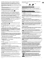 47
47
-
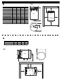 48
48
-
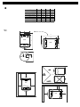 49
49
-
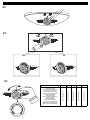 50
50
-
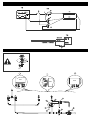 51
51
-
 52
52


Tesy ELECTRIC WATER HEATER Mode d'emploi
- Taper
- Mode d'emploi
dans d''autres langues
Documents connexes
Autres documents
-
 Eldom Invest 60-100 DU Guide d'installation
-
clage E-Convenience Instant Water Heater Manuel utilisateur
-
clage DLX Next Mode d'emploi
-
Gorenje TEG10U Le manuel du propriétaire
-
-
-
-
Centrometal CAS, CAS-S, CAS-B, CAS-BS Technical Instructions
