
INSTRUCTION MANUAL
MODEL: KC-760L
6” X 48” BELT & 9” DISC SANDER
PONCEUSE À COURROIE 6” X 48”
ET À DISQUE 9”
MANUEL D’INSTRUCTIONS
COPYRIGHT © 2018 ALL RIGHTS RESERVED BY KING CANADA TOOLS INC.
DROITS D’AUTEURS © 2018 TOUS DROITS RÉSERVÉS PAR OUTILLAGES KING CANADA INC.
MODÈLE: KC-760L

WARRANTY INFORMATION
2-YEAR
LIMITED WARRANTY
FOR THIS BELT AND DISC SANDER
KING CANADA TOOLS
OFFERS A 2-YEAR LIMITED WARRANTY
FOR NON-COMMERCIAL USE.
PROOF OF PURCHASE
Please keep your dated proof of purchase for warranty and servicing purposes.
REPLACEMENT PARTS
Replacement parts for this product are available at our authorized King Canada service centers across Canada. Please use the 10 digit
part numbers listed in this manual for all part orders where applicable.
LIMITED TOOL WARRANTY
King Canada makes every effort to ensure that this product meets high quality and durability standards. King Canada warrants to the
original retail consumer a 2-year limited warranty as of the date the product was purchased at retail and that each product is free from
defects in materials. Warranty does not apply to defects due directly or indirectly to misuse, abuse, normal wear and tear, negligence
or accidents, repairs done by an unauthorized service center, alterations and lack of maintenance. King Canada shall in no event be
liable for death, injuries to persons or property or for incidental, special or consequential damages arising from the use of our products.
To take advantage of this limited warranty, return the product at your expense together with your dated proof of purchase to an
authorized King Canada service center. Contact your retailer or visit our web site at www.kingcanada.com for an updated listing of our
authorized service centers. In cooperation with our authorized service center, King Canada will either repair or replace the product if
any part or parts covered under this warranty which examination proves to be defective in workmanship or material during the
warranty period.
NOTE TO USER
This instruction manual is meant to serve as a guide only. Specifications and references are subject to change without prior notice.
KING CANADA INC. DORVAL, QUÉBEC, CANADA H9P 2Y4
www.kingcanada.com
INFORMATION SUR LA GARANTIE
GARANTIE LIMITÉE
2-ANS
POUR CETTE PONCEUSE À COURROIE ET À DISQUE
OUTILLAGES KING CANADA
OFFRE UNE GARANTIE LIMITÉE DE 2 ANS
POUR USAGE DOMESTIQUE
PREUVE D’ACHAT
S.V.P. gardez votre preuve d’achat pour la garantie et le service d’entretien de votre produit.
PIÈCES DE RECHANGE
Les pièces de rechange pour ce produit sont disponibles à nos centres de service autorisés King Canada à travers le Canada. S.V.P.
utilisez les numéros à 10 chiffres indiqués dans la liste des pièces de ce manuel pour toute commande de pièces.
GARANTIE LIMITÉE
King Canada fait tous les efforts pour assurer que nos produits soient satisfaisants aux standards de qualité et de durabilité. King Canada
offre aux consommateurs une garantie limitée de 2 ans, dès la date d’achat, que chaque produit est sans défauts de matériaux. La
garantie ne s’applique pas aux défauts causés directement ou indirectement à l’abus, usage normale, négligence ou accidents,
réparations effectuées par un centre de service non-autorisé, modifications et manque de maintenance. King Canada ne sera en aucun
temps responsable pour les accidents mortels ou blessures à la personne ou à la propriété ou dans le cas d’incidents, en cas spécial
ou dommages-intérêts indirects survenus pendant l’utilisation de nos produits.
Pour profiter de cette garantie limitée, retournez le produit à vos frais ensemble avec votre preuve d’achat à un centre de service
autorisé King Canada. Contactez votre distributeur ou visitez notre site web à www.kingcanada.com pour obtenir une liste à jour de nos
centres de service autorisés King Canada. En coopération avec notre centre de service autorisé, durant la période de garantie,
King Canada va soit réparer ou remplacer le produit si l’inspection prouve qu’une ou plusièures pièces couverts sous cette garantie
sonts défectueuses.
NOTE À L’UTILISATEUR
Les instructions dans ce manuel servent comme guide seulement. Les spécifications et références sont sujets à changement sans
préavi.
KING CANADA INC. DORVAL, QUÉBEC, CANADA H9P 2Y4
www.kingcanada.com

GENERAL & SPECIFIC
SAFETY INSTRUCTIONS
1. Wear eye protection.
2. Support workpiece with backstop or work table.
3. Maintain 1/16’’ maximum clearance between table and
sanding belt or disc.
4. Hold the workpiece firmly, so that it may not be driven from
your hands.
5. In operation, do not press on the belt. Excessive pressure
against the belt is never necessary. It will only result in damage
to the belt or workpiece.
6. At home, where there are young children, a good practice is to
unplug the motor and remove the switch key when the
sander is not in operation.
7. Feed workpiece against rotation of sander.
VOLTAGEWARNING: Before connecting the tool to a power source (receptacle, outlet, etc.) be sure the voltage supplied is the same
as that specified on the nameplate of the tool. A power source with voltage greater than that for the specified tool can result in SERIOUS
INJURY to the user - as well as damage to the tool. If in doubt DO NOT PLUG IN THE TOOL. Using a power source with voltage less
is harmful to the motor.
1. KNOW YOUR TOOL
Read and understand the owners manual and labels affixed to
the tool. Learn its application and limitations as well as its
specific potential hazards.
2. GROUND THE TOOL.
This tool is equipped with an approved 3-conductor cord and
a 3-prong grounding type plug to fit the proper grounding type
receptacle. The green conductor in the cord is the grounding
wire. NEVER connect the green wire to a live terminal.
3. KEEP GUARDS IN PLACE.
Keep in good working order, properly adjusted and aligned.
4. REMOVE ADJUSTING KEYS AND WRENCHES.
Form habit of checking to see that keys and adjusting
wrenches are removed from tool before turning it on.
5. KEEP WORK AREA CLEAN.
Cluttered areas and benches invite accidents. Make sure the
floor is clean and not slippery due dust build-up.
6. AVOID DANGEROUS ENVIRONMENT.
Don’t use power tools in damp or wet locations or expose
them to rain. Keep work area well lit and provide adequate
surrounding work space.
7. KEEP CHILDREN AWAY.
All visitors should be kept a safe distance from work area.
8. MAKE WORKSHOP CHILD-PROOF.
Use padlocks, master switches or remove starter keys.
9. USE PROPER SPEED.
A tool will do a better and safer job when operated at the
proper speed.
10. USE RIGHT TOOL.
Don’t force the tool or the attachment to do a job for which it
was not designed.
11. WEAR PROPER APPAREL.
Do not wear loose clothing, gloves, neckties or jewelry (rings,
watch) because they could get caught in moving parts.
Non-slip footwear is recommended. Wear protective hair
covering to contain long hair. Roll up long sleeves above the
elbows.
12. ALWAYS WEAR SAFETY GLASSES.
Always wear safety glasses (ANSI Z87.1). Everyday
glasses only have impact resistant lenses, they are NOT
safety glasses. Also use a face or dust mask if cutting
operation is dusty.
13. DON’T OVERREACH.
Keep proper footing and balance at all times.
14. MAINTAIN TOOL WITH CARE.
Keep tools sharp and clean for best and safest performance.
Follow instructions for lubricating and changing accessories.
15. DISCONNECT TOOLS.
Before servicing, when changing accessories or attachments.
16. AVOID ACCIDENTAL STARTING.
Make sure the switch is in the ‘’OFF’’ position before plugging
in.
17. USE RECOMMENDED ACCESSORIES.
Consult the manual for recommended accessories. Follow the
instructions that accompany the accessories. The use of
improper accessories may cause hazards.
18. NEVER STAND ON TOOL.
Serious injury could occur if the tool tips over. Do not store
materials such that it is necessary to stand on the tool to reach
them.
19. CHECK DAMAGED PARTS.
Before further use of the tool, a guard or other parts that are
damaged should be carefully checked to ensure that they will
operate properly and perform their intended function. Check for
alignment of moving parts, breakage of parts, mounting, and
any other conditions that may affect its operation. A guard or
other parts that are damaged should be properly repaired or
replaced.
20. NEVER LEAVE MACHINE RUNNING UNATTENDED.
Turn power ‘’OFF’’. Don’t leave any tool running until it comes
to a complete stop.
SPECIFIC SAFETY INSTRUCTIONS
DIRECTIVES DE SÉCURITÉ
GÉNÉRALES ET SPÉCIFIQUES
1. Portez des lunettes de sécurité.
2. Supportez la pièce de travail adéquatement et bien la contrôler
à tout moment.
3. Gardez 1/16” de dégagement entre la table inclinable et la
courroie ou le disque.
4. Tenez la pièce fermement pour ne pas l’échapper
involontairement.
5. Ne pas mettre de la pression inutile sur la courroie. Une
pression excessive contre la courroie ne fera qu’endommagée la
courroie et la pièce de travail.
6. Mettre la machine à l’abri des enfants en débranchant le
moteur et en enlevant la clé de l’interrupteur.
7. La pièce de travail ne doit entrer en contact avec la courroie ou
le disque que dans le sens opposé à sa rotation.
ATTENTION AU VOLTAGE: Avant de brancher l’outil à une prise (réceptacle, sortie d’éléctrique etc.), il faut s’assurer que le voltage est
le même que celui qui est spécifié sur la plaque de l’outil. Une prise de courant avec un voltage supérieur à celui qui est spécifié sur
l’outil peut causer de SERIEUSES BLESSURES à l’utilisateur et endommager l’outil. Dans le doute, NE PAS BRANCHEZ L’OUTIL.
L’usage d’une source de courant avec un voltage inférieur à celui qui est spécifié sur la plaque endommagera le moteur.
1. CONNAÎTRE VOTRE OUTIL.
Lisez et comprenez le manuel d’instructions et les étiquettes
sur l’outil. Apprenez ses applications et ses limites ainsi que
les dangers spécifiquement reliés.
2. EFFECTUE UNE MISE À LA TERRE.
Cet outil est équipé d’un cordon à 3 brins ainsi qu’une prise à
3 fiches pour la mise à la terre. Inserrez cette prise dans une
prise murale mise à la terre. Le brin vert dans le cordon est le
brin pour la mise à la terre. NE JAMAIS brancher le brin vert
à un terminal ouvert.
3. MAINTENEZ LES GARDES EN PLACE.
Gardez-les en bon état de fonctionnement, correctement
ajustés et alignés.
4. RETIREZ LES CLÉS D’AJUSTEMENTS.
Prenez l’habitude de vérifier si les clés d’ajustements sont
retirées de l’outil avant de mettre la machine en marche.
5. GARDEZ VOTRE ATELIER PROPRE.
Assurez-vous que le plancher est propre en tout temps et qu’il
ne soit pas glissant dû à la cire ou à une accumulation de
poussière.
6. ÉVITEZ LES ENVIRONNEMENTS DANGEREUX.
N’utilisez pas un outil dans un emplacement humide ou
mouillé et ne l’exposez pas à la pluie. Gardez l’atelier bien
éclairé et gardez-vous beaucoup d’espace pour travailler.
7. GARDEZ LES ENFANTS ÉLOIGNÉS.
Gardez les enfants et les visiteurs à l’écart de votre atelier.
8. METTRE L’ATELIER HORS DE LA PORTÉE DES ENFANTS
Avec des cadenas, des interrupteurs principaux ou en retirant
la clé de sécurité.
9. UTILISEZ LA BONNE VITESSE.
Un outil fonctionnera mieux et plus sécuritairement si vous
l’opérez à la bonne vitesse.
10. UTILISEZ LE BON OUTIL.
Ne forcez pas l’outil ou l’accessoire à faire un travail pour
lequel il n’a pas été conçu.
11. PORTEZ DES VÊTEMENTS CONVENABLES.
Ne portez pas de vêtements amples, gants, cravates ou bijoux
(bagues, montre) parce qu’ils peuvent se coincer dans des
pièces mobiles. Des souliers anti-dérapants sont
recommandés. Protégez vos cheveux et roulez vos manches
jusqu’aux coudes.
12. PORTEZ TOUJOURS DES LUNETTES DE SÉCURITÉ.
Portez toujours des lunettes de sécurité (ANSI Z87.1). Des
lunettes pour la vue ont seulement des verres résistants à
l’impact, ils ne sont pas des lunettes de sécurité. Utilisez un
masque facial si l’opération devient poussièreuse.
13. NE PAS S’ÉTENDRE AU-DESSUS DE L’OUTIL.
Gardez votre équilibre en tout temps.
14. MAINTENEZ L’OUTIL AVEC SOIN.
Gardez vos outils propres et bien aiguisés pour une meilleure
performance. Suivez les instructions de lubrification et de
changements des accessoires.
15. DÉBRANCHEZ L’OUTIL.
Avant toutes réparations, changement d’accessoires ou
d’ajustements.
16. ÉVITEZ LES DÉMARRAGES ACCIDENTELS.
Assurez-vous que l’interrupteur est dans la position ‘’OFF’’
avant de brancher.
17. UTILISEZ SEULEMENT LES ACCESSOIRES
RECOMMANDÉS.
Consultez le manuel pour les accessoires recommandés.
Suivez les instructions qui accompagnent les accessoires.
18. NE MONTEZ PAS SUR L’OUTIL.
De graves blessures peuvent se produire si l’outil bascule.
19. VÉRIFIEZ LES PIÈCES ENDOMMAGÉES.
Avant l’utilisation, un garde ou autres pièces endommagés
devraient être vérifiés pour assurer qu’ils fonctionnent
adéquatement. Vérifiez l’alignement des pièces mobiles,
fissures dans les pièces, assemblage, et toutes autres
conditions qui peuvent affecter le fonctionnement. Réparez ou
remplacez toutes les pièces endommagées.
20. NE JAMAIS LAISSEZ L’OUTIL SANS SURVEILLANCE.
Mettez l’interrupteur à la position ‘’OFF’’. Ne quittez pas
jusqu’à ce que l’outil s’arrête complètement.
DIRECTIVES DE SÉCURITÉ SPÉCIFIQUES

ELECTRICAL INFORMATION &
TURNING ON YOUR SANDER
WARNING!
ALL ELECTRICAL CONNECTIONS MUST BE DONE BY A QUALIFIED ELECTRICIAN. FAILURE TO COMPLY MAY RESULT IN
SERIOUS INJURY! ALL ADJUSTMENTS OR REPAIRS MUST BE DONE WITH THE MACHINE DISCONNECTED FROM THE
POWER SOURCE. FAILURE TO COMPLY MAY RESULT IN SERIOUS INJURY!
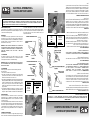
LENGTH OF
CONDUCTOR
0-25 FEET
26-50 FEET
51-100 FEET
WIRE SIZES REQUIRED
(AMERICAN WIRE GAUGE)
120V LINES
NO.14
NO.14
NO.12
FIGURE 2
PROPERLY GROUNDED OUTLET
CURRENT CARRYING
PRONGS
POWER SOURCE (120/240V)
Your sander’s motor was designed for a specific frequency and voltage.
Make sure the voltage indicated on the machine nameplate corresponds
to the electrical outlet voltage output.
GROUNDING
Your sander must be properly grounded. Not all outlets are properly
grounded. If you are not sure if your outlet is properly grounded, have it
checked by a qualified electrician. If it should malfunction or breakdown,
grounding provides a path of least resistance for electric current, to
reduce the risk of electric shock.
WARNING: IF NOT PROPERLY GROUNDED, THIS SANDER CAN
CAUSE ELECTRICAL SHOCK, PARTICULARLY WHEN USED IN DAMP
LOCATIONS. TO AVOID SHOCK OR FIRE, IF THE POWER CORD IS
WORN OR DAMAGED IN ANY WAY, HAVE IT REPLACED
IMMEDIATELY.
120V OPERATION
As received from the factory, your sander is ready to run for 120V
operation. This sander is intended for use on a circuit that has an outlet
and a plug which looks like the one illustrated in Fig.1.
WARNING: DO NOT USE A TWO-PRONG ADAPTORS FOR THEY ARE
NOT IN ACCORDANCE WITH LOCAL CODES AND ORDINANCES.
NEVER USE IN CANADA.
240V OPERATION
If 240V, single phase operation is desired, the following instructions
must be followed:
1. Disconnect the machine from its power source.
2. The sander comes with four motor leads that are connected for 120V
operation. Reconnect these four motor leads for 240V operation, as
indicated on the inside of the connections cover.
3. The 120V plug supplied with the sander must be replaced with a CSA
listed plug suitable for 240V operation. This plug is illustrated in Fig.2.
Contact your authorized service center or qualified electrician to install
the plug and to change the connections from 120V to 240V. The
sander must comply with all local and national codes after the 240V
plug is installed.
4. A sander with a 240V plug should only be connected to an outlet
having the same configuration as illustrated by the grounded outlet box
in Fig.2. No adaptor is available or should be used for 240V operation.
EXTENSION CORDS
The use of any extension cord will cause some loss of power. Use the
following table Fig.3 to determine the minimum wire size (A.W.G-
American Wire Gauge) extension cord. Use only extension cords which
accept the tool’s plug.
For circuits that are further away from the electrical circuit box, the wire size
must be increased proportionately in order to deliver ample voltage to the
motor. Refer to Fig.3 for wire length and size. Use only 3-wire extension
cords which have 3-prong grounding type plugs and 3-hole receptacles
which accept the tool’s plug. If the extension cord is cut or damaged, do
not use it.
TURNING ON YOUR SANDER
The sander motor is controlled by a toggle switch (A) Fig.4, this toggle
switch comes with a removeable safety key (B) which limits the usage of
PROPERLY GROUNDED OUTLET
CURRENT CARRYING
PRONGS
GROUNDING PRONG
GROUNDING
PRONG
FIGURE 1
FIGURE 3
FIGURE 4
your sander to authorized users. To turn sander on, move the switch
to the “ON” position, to turn sander off, move the switch to the “OFF”
position. To lock the switch once the sander is off, pull the safety key
(B) out. The sander can not be turned on until the safety key is
repositioned in the switch.
Source d’alimentation électrique
Le moteur a été conçu pour une fréquence et un voltage spécifique. Vérifiez
le voltage de votre entré électrique avant de brancher la machine afin de vous
assurer que le voltage correspond au voltage inscrit sur le moteur.
MISE À LA TERRE
Votre ponceuse doit être correctement mise à la terre. Les prises murales ne
sont pas toutes mise à la terre. Si vous avez des doutes, ou que vous ne
comprenez pas les instructions de mise à la terre; vérifiez avec un électricien
compétent si la machine est bien branchée. S’il y a une interruption ou une
panne, la mise à la terre fournit un passage avec moins de résistance, qui
réduit les risques de chocs électriques.
AVERTISSEMENT: S’IL N’EST PAS MISE À LA TERRE, VOTRE
PONCEUSE PEUT PRODUIRE DES CHOCS ÉLECTRIQUES,
PARTICULIÈREMENT LORSQUE VOUS L’UTILISEZ DANS UN
EMPLACEMENT HUMIDE. SI LE CORDON D’ALIMENTATION EST
ENDOMMAGÉ, REMPLACEZ-LE IMMÉDIATEMENT, POUR ÉVITER LES
CHOCS ÉLECTRIQUES OU LE FEU.
OPÉRATION SUR LE 120V
Quand cette ponceuse est branchée sur le 120V, vous devez utiliser une
prise murale tel qu’illustrée à la Fig.1.
AVERTISSEMENT: N’UTILISEZ PAS D’ADAPTATEURS. ILS NE SONT PAS
EN ACCORD SELON LES NORMES EN VIGUEUR . NE JAMAIS UTILISEZ
UN ADAPTATEUR AU CANADA.
OPÉRATION SUR LE 240V
Si l’opération 240V, 1 phase est désirée, suivez les instructions suivantes:
1. Débranchez la machine de la source de courant.
2. Le boîtier du moteur contient 4 fils électriques qui sont branchés sur le
120V. Reconnectez ces 4 fils pour le 240V tel qu’illustré à l’intérieur du
couvercle de connections électriques.
3. La prise 120V fournie avec la ponceuse doit être remplacée par une prise
CSA 240V. Cette prise est illustrée à la Fig.2. Contactez votre centre de
service autorisé ou un technicien qualifié pour installer la prise et changer
les connections de 120V à 240V.
4. Aucun adaptateur n’est disponible ou ne devrait être utilisé sur le 240V.
RALLONGES
L’utilisation de n’importe quelle rallonge produira une perte de puissance.
Utilisez le tableau Fig.3 pour déterminer le calibre minimale de rallonge à
utiliser (A.W.G-American Wire Gauge). Utilisez seulement des rallonges à 3
brins type mise à la terre et une prise murale à 3 fiches. Pour des circuits plus
éloignés de la boîte électrique, le calibre du fil doit être augmentée
proportionnellement pour pouvoir distribuer amplement de voltage au moteur
de la ponceuse.
METTRE LA PONCEUSE EN MARCHE
Le moteur de cette ponceuse est contrôlé par l’interrupteur (A) Fig.4, cet
interrupteur comprend une clé de sécurité amovible (B), cette clé peut être
enlevée pour limiter l’usage. Pour mettre la ponceuse en marche, placez
l’interrupteur à la position “ON”, pour arrêter la ponceuse, placez l’interrupteur
à la position “OFF”. Pour verrouiller l’interrupteur, retirez la clé de sécurité (B).
L’interrupteur ne fonctionnera pas avant que la clé de sécurité soit remise en
place.
AVERTISSEMENT!
TOUS BRANCHEMENTS ÉLECTRIQUES DOIVENT ÊTRE EFFECTUÉS PAR UN TECHNICIEN QUALIFIÉ. TOUS AJUSTEMENTS ET
RÉPARATIONS DOIVENT ÊTRE ENTREPRIS LORSQUE LA MACHINE EST DÉBRANCHÉE SINON, IL Y A RISQUES DE
PRODUIRE DE GRAVES BLESSURES!
PRISE MURALE MISE À LA TERRE
FICHES
FICHE POUR LA
MISE À LA TERRE
PRISE MURALE MISE À LA TERRE
FICHES
FICHE POUR LA
MISE À LA TERRE
FIGURE 2
FIGURE 1
FIGURE 3
FIGURE 4
LONGUEUR DE
RALLONGE
0-25 PIEDS
26-50 PIEDS
51-100 PIEDS
CALIBRE NÉCESSAIRE
(AMERICAN WIRE GAUGE)
120V
NO.14
NO.14
NO.12
INFORMATION ÉLECTRIQUE ET
METTRE LA PONCEUSE EN MARCHE

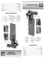
GETTING TO KNOW YOUR SANDER
SANDER SPECIFICATIONS
Model ........................................................................................................................................................................................KC-760L
Voltage ..................................................................................................................................................................................120V/240V
Amperage ..........................................................................................................................................10 Amp. @ 120V/5 Amp. @ 240V
Motor RPM’s..........................................................................................................................................................................1,740 RPM
Prewired ..........................................................................................................................................................................................120V
Sanding belt size ........................................................................................................................................................................6” x 48”
Sanding belt speed ..............................................................................................................................................................1,250 ft/min
Sanding disc size ................................................................................................................................................................................9”
Sanding disc speed ..............................................................................................................................................................1,740 RPM
Sanding belt angle range ............................................................................................................................................................0º - 90º
Tilting table angle range ..............................................................................................................................................................0º - 45º
1. Adjustable rubbet feet (4)
2. Cabinet stand door
3. Cabinet stand
4. 2-1/2” Disc dust chute
5. Table angle lock knob
6. Disc or belt tilting table
7. Miter gauge
8. 9” Sanding disc
9. Backstop
10. 6” x 48” Sanding belt
11. Belt tracking adjustment (2)
12. Belt tension release lever
13. Lower belt guard
14. End belt guard
15. Switch with safety key
16. Adjustable 2-1/2” belt dust
chute (shown with #17)
17. 2-1/2” to 4” dust chute adaptor
18. Belt angle lock nut (1 of 2)
19. Belt angle scale
APPRENDRE À CONNAÎTRE
VOTRE PONCEUSE
SPÉCIFICATIONS DE VOTRE PONCEUSE
Modèle ......................................................................................................................................................................................KC-760L
Voltage ..................................................................................................................................................................................120V/240V
Ampérage ..........................................................................................................................................10 Amp. @ 120V/5 Amp. @ 240V
Tours minute du moteur........................................................................................................................................................1,740 tr/min
Pré-cablé ........................................................................................................................................................................................120V
Dimension de la courroie ............................................................................................................................................................6” x 48”
Vitesse de la courroie ..........................................................................................................................................................1,250 pi/min
Dimension du disque............................................................................................................................................................................9”
Vitesse du disque ................................................................................................................................................................1,740 tr/min
Angles possibles de la courroie ..................................................................................................................................................0º - 90º
Angles possibles de la table inclinable........................................................................................................................................0º - 45º
1. Pieds en caoutchouc ajustables (4)
2. Porte du cabinet fermé
3. Cabinet fermé
4. Sortie de poussière 2-1/2” du disque
5. Bouton de verrouillage de la table inclinable
6. Table inclinable pour disque ou courroie
7. Guide à onglets
8. Disque de ponçage 9”
9. Butée d’arrêt
10. Courroie de ponçage 6” x 48”
11. Écrou d’alignement de la courroie
12. Levier de tension de la courroie
13. Garde de sécurité inférieur
14. Garde de sécurité du bout
15. Interrupteur avec clé de sécurité
16. Sortie de poussière ajustable 2-1/2”
(illustré avec #17)
17. Adaptateur pour sortie de poussière
2-1/2” à 4”
18. Écrou de verrouillage de l’angle de la
courroie (1 de 2)
19. Échelle d’angle de la courroie

ASSEMBLY
UNPACKING
Remove all loose parts from the carton. Carefully lift the sander from the carton
and place it on a level work surface. Remove all other items from the carton and
follow all of the following assembly, adjustments, operation and maintenance
instructions in this manual.
ASSEMBLING 4 PANELS OF CABINET STAND
Assemble the 2 side panels (A) Fig.5 and 2 front/rear panels (B) of the cabinet
stand together using 8 hex. bolts, 16 washers, 8 spring washers and 8 hex. nuts.
INSTALLING RUBBER FEET TO CABINET STAND
Once the cabinet stand is securely assembled, position the cabinet stand on its
side and install the adjustable rubber feet (A) to each corner of the cabinet stand
as shown in Fig.6. Reposition the cabinet stand upright and place it in the
location you plan on using your sander. Check to see if the cabinet stand is level
and stable, if the cabinet stand is not stable, adjust the rubber feet in or out on all
corners until the cabinet stand stays firmly in place.
MOUNTING TOP PLATE OF CABINET STAND TO BASE OF SANDER
Position the sander assembly on its side and mount the top plate (A) Fig.7 to the
underside of the sander base using 4 hex. bolts and 4 washers.
MOUNTING SANDER ASSEMBLY & TOP PLATE TO CABINET STAND
Position the sander assembly and the top plate on top of the cabinet stand, line
up the mounting holes and secure the top plate to the cabinet stand using 4 pan
hd screws and washers (A). See Fig.8.
Figure 5
Figure 6
Figure 8
Figure 7
MONTAGE
DÉBALLAGE
Retirez toutes les pièces libres de la boîte. Soyez prudent et retirez la ponceuse
de la boîte et placez-la sur une surface de travail à niveau. Avant d’operer cette
ponceuse, il est nécessaire de suivre les instructions d’assemblage,
d’ajustements, d’opération et de maintenance suivantes:
ASSEMBLAGE DES QUATRE PANEAUX DU SUPPORT À CABINET
Assemblez les deux panneaux de côté (A) Fig.5 et les deux panneaux
avant/arrière (B) ensemble en utilisant 8 boulons hexagonaux, 16 rondelles, 8
rondelles à ressort et 8 écrous hexagonaux.
INSTALLATION DES PIEDS EN CAOUTCHOUC AU SUPPORT À CABINET
Une fois que le support à cabinet est complètement assemblé, positionnez-le sur
sont côté et installez les quatre pieds en caoutchouc (A) aux quatre coins du
support tel qu’illustré à la Fig.6. Repositionnez le support à cabinet sur ces
quatre pieds en caoutchouc et placez-le dans l’emplacement où vous prévoyez
utiliser la ponceuse. Vérifiez si le support à cabinet est stable et à niveau, si le
support n’est pas stable, adjustez les pieds en caoutchouc jusqu’à ce qu’il soit
parfaitement stable.
INSTALLATION DE LA PLAQUE DU SUPPORT À CABINET À LA BASE DE
LA PONCEUSE
Positionnez la ponceuse sur sont côté est installez la plaque du support (A) Fig.7
du cabinet sous la base de la ponceuse en utilisant 4 boulons hexagonaux et 4
rondelles.
INSTALLATION DE LA PONCEUSE ET LA PLAQUE SUR LE SUPPORT À
CABINET
Positionnez la ponceuse et la plaque sur le dessus du support à cabinet, ensuite
alignez les trous des montage et fixez la plaque au support en utilisant 4 vis à
tête bombée et 4 rondelles (A). Voir Fig.8.
Figure 5
Figure 6
Figure 8
Figure 7

ASSEMBLY
MONTAGE
INSTALLING 9” PSA SANDING DISC
A 9” sanding disc for pressure sensitive adhesive (PSA) backed discs is supplied
with this sander. If you wish to install it or any other adhesive 9” sanding disc,
follow these instructions:
1. Undo and remove the sanding disc cover lock knob (A) Fig.9 and open the
sanding disc cover (B).
2. Before installing any sanding disc, the disc (C) must be clean and free of any
debris or else you may experience unsatisfactory sanding results or disc may
loose contact with the plate and be projected into the air.
3. Peel the paper backing from the sanding disc, carefully position and press the
sanding disc (A) Fig.10 firmly to the disc.
4. Close the sanding disc cover and lock it in place using the same lock knob.
See Fig.10.
WARNING! Never attempt to use the sanding disc without the tilting table
installed 1/16” away from the sanding disc, see instructions below.
INSTALLING TILTING TABLE ASSEMBLY IN FRONT OF SANDING DISC
The most common place to install the tilting table is in front of the sanding disc
because support is required during sanding disc operations. To install the tilting
table, follow these instructions:
1. Locate the support shaft (A) Fig.11 and insert it into the support shaft opening.
Tighten the 2 set screws (B) against the flats of the support shaft with a 5mm
hex. key.
2. Slide the tilting table assembly (C) onto the support shaft (A) until the table is
maximum 1/16” away from the sanding disc.
3. Tighten the 4 set screws (D) on both sides of the tilting table bracket against
the flats of the support shaft with a 6mm hex. key.
PLACE MITER GAUGE ASSEMBLY ON TILTING TABLE
Slide the miter gauge assembly (A) Fig.12 into the tilting table slot. The miter
gauge is now ready to be used.
Figure 9
Figure 10
Figure 12
Figure 11
INSTALLATION DU DISQUE DE PONÇAGE 9” ASP
Un disque de ponçage de 9” avec adhésif sensible à la pression (ASP) est fourni
avec votre ponceuse. Si vous désiré l’installer ou installer autres disques, suivre
les instructions suivantes:
1. Dévissez et retirez le bouton de verrouillage (A) Fig.9 et ouvrez le couvercle
du disque (B).
2. Avant d’installer un disque de ponçage, le disque en aluminium (C) doit être
parfaitement propre sinon il est possible que les opérations de ponçage du
disque soient moins que satisfaisants ou le disque de ponçage pourrait perdre
sont adhésion et sera projeté dans l’air.
3. La pellicule adhésive doit être enlevée à l’arrière du disque de ponçage (A)
Fig.10. Une pression doit être appliquée afin que les deux surfaces collent
bien.
4. Fermez le couvercle du disque de ponçage et verrouillez-le en place en
utilisant le même bouton de verrouillage. Voir Fig.10.
AVERTISSEMENT! Ne jamais tenter d’effectuer une opération de ponçage avec
le disque sans avoir installer la table inclinable. La distance entre la table et le
disque de ponçage ne doit pas excéder 1/16”, voir les instructions suivantes.
INSTALLATION DE LA TABLE INCLINABLE AU DISQUE DE PONÇAGE
La position la plus commune de la table inclinable est en avant du disque de
ponçage car un support de la pièce de travail est nécesaire. Pour installer la table
inclinable, suivre les instructions suivantes:
1. Insérrez la tige de support (A) Fig.11 dans l’ouverture de support. Serrez les
deux vis sans tête (B) avec une clé hexagonale de 5mm contre les deux côtés
à plât de la tige de support.
2. Glissez la table inclinable (C) sur la tige de support (A) jusqu’à ce que la table
soit à un maximum de 1/16” du disque de ponçage.
3. Serrez les quatre vis sans tête (D) (qui se trouvent des deux côtés du support
de table) contre les deux côtés à plât de la tige de support avec une clé
hexagonale de 5mm.
PLACEZ LE GUIDE À ONGLETS SUR LA TABLE INCLINABLE
Glissez le guide à onglets assemblé (A) Fig.12 dans la rainure de la table
inclinable. Le guide à onglets est maintenant prêt pour l’utilisation.
Figure 9
Figure 10
Figure 12
Figure 11

ASSEMBLY & ADJUSTMENTS
MONTAGE ET AJUSTEMENTS
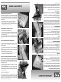
INSTALLING BELT TABLE END SAFETY GUARD
The belt table end safety guard (A) Fig. 13 is not installed and should be installed
to ensure user safety during sanding operations. If you desire to make internal
curve sanding which requires the use of the drum portion of the sanding belt, this
end safety guard must not be installed. To install the end safety guard, follow
these instructions:
1. Undo and remove the 2 lock knobs (B) on both sides of the belt table.
2. Slide the end safety guard (A) under the lower safety guard tabs (C).
3. Line up the mounting holes and secure both safety guards together by
reinstalling the 2 lock knobs removed previously.
INSTALLING BELT DUST CHUTE WITH 2-1/2” OUTLET
To install the belt dust chute, follow these instructions:
1. Undo the 2 pan hd screws (B) from the belt casting and position the belt dust
chute (A) Fig.14 as shown and fasten it to the belt casting using the 2 pan hd
screws removed previously.
2. If you desire to connect this sander to dust collection system which uses a 4”
flex hose, install the supplied 2-1/2” to 4” dust chute adaptor (C) as shown in
Fig.14.
ADJUSTING SANDING BELT VERTICALLY OR HORIZONTALLY
The belt housing can be positioned horizontally or vertically. It can also be
positioned at any angle in between depending on your sanding needs. To adjust,
follow these instructions:
1. Loosen the two lock nuts (A) Fig.15 (the second hex. nut is under the one
shown).
2. Slowly lift or lower the belt housing to the desired angle. See scale (B) for the
sanding belt angle.
3. To secure into position, retighten the two lock nuts (A).
4. To obtain the perfect horizontal position, lower completely until it comes in
contact with the stop bolt underneath the belt housing.
INSTALLING TILTING TABLE TO SANDING BELT (VERTICAL POSITION)
As mentioned previously, the tilting table is most commonly installed to the
sanding disc but it can also be installed to the sanding belt when it is in its
vertical position. Please note the belt dust chute must be repositioned in order to
allow connecting a dust collection hose. To install the tilting table to the sanding
belt, follow these instructions:
1. Remove the tilting table assembly from the sanding disc position and
reposition it as shown in Fig.16.
2. Position the tilting table maximum 1/16” away from the sanding belt and then
secure the support shaft (A) Fig.16 in place by tightening the 2 set screws (B).
3. Before making vertical sanding belt operations with the tilting table installed,
remove the belt backstop.
ADJUSTING TILTING TABLE ANGLE
The tilting table can be tilted from 0º- 45º by loosening the table lock knob (C)
Fig.16, tilt the table to the desired angle as indicated on the table scale (D) and
retighten lock knob. Make sure the desired angle is true, to set the table square
with the belt, use a combination square. If the angle pointer needs to be
repositioned, loosen pointer screw and readjust.
Figure 13
Figure 14
Figure 16
Figure 15
INSTALLATION DU GARDE DE SÉCURITÉ DU BOUT
Le garde de sécurité du bout (A) Fig. 13 n’est pas installer et devrait l’être pour
assurer une protection à l’utilisateur pendant les opérations de ponçage. Ce
garde ne doit être installer si vous désirez effectuer le ponçage de courbe
internes (qui utilise la partie du tambour du bout de la courroie de ponçage). Pour
installer le garde de sécurité du bout, suivre les instructions suivantes:
1. Dévissez et retirez les deux boutons de verrouillage (B) qui se trouvent de
chaque côté de la courroie de ponçage.
2. Glissez le garde de sécurité du bout (A) sous les deux attaches (C).
3. Alignez les trous de montage et fixez les deux gardes de sécurité ensembles
en utilisant les deux boutons de verrouillage.
INSTALLATION DE LA SORTIE DE POUSSIÈRE DE 2-1/2” DE LA COURROIE
DE PONÇAGE
Pour installer la sortie de poussière de la courroie de ponçage, suivre les
instructions suivantes:
1. Retirez les deux vis à tête bombée (B) qui sont vissées dans le boîtier de la
table et positionnez la sortie de poussière (A) Fig.14 tel qu’illustré et fixez-la au
boîtier de la table en utilisant les même deux vis à tête bombée retirées
précédamment.
2. Si vous désirez brancher cette ponceuse à un système de collection de
poussière avec un boyau de 4”, installez l’adaptateur de 2-1/2” à 4” (C) tel
qu’illustré à la Fig.14.
AJUSTEMENT DE LA COURRIE DE PONÇAGE EN POSITION
HORIZONATLE OU VERTICALE
Le boîtier de la courroie peut être placé en complète position verticale ou
horizontale. Il peut également être placé à n’importe quelle position pouvant
convenir à l’éxécution du ponçage. Pour le réglage suivez les instructions
suivantes:
1. Desserrez les deux écrous de fixation (A) Fig.15 (le deuxième écrou est sous
le boîtier de la courroie).
2. Lentement, soulevez ou abaissez le boîtier de la courroie à l’angle désiré.
Référez-vous à l’échelle (B) pour l’angle.
3. Pour fixer en position, serrez le deux écrous de fixation (A).
4. Pour obtenir une position horizontale, un boulon d’arrêt est fixé sous le boîtier
de la courroie pour l’arrêter.
INSTALLATION DE LA TABLE INCLINABLE À LA COURROIE DE PONÇAGE
(POSITION VERTICALE)
La position la plus commune de la table inclinable est en avant du disque de
ponçage car un support de la pièce de travail est nécesaire, mais il est aussi
possible d’installer la table inclinable à la courroie de ponçage lorsqu’elle est en
position verticale. Notez que la sortie de poussière de la courroie doit être
repositionnée pour permettre le branchement d’un boyau d’un collecteur de
poussière. Pour installer la table inclinable à la courroie, suivre les instructions
suivantes:
1. Retirez l’ensemble de la table inclinable à l’avant du disque et repositionnez-
le tel qu’illustré à la Fig.16.
2. Positionnez la table inclinable à un maximum de 1/16” de la courroie de
ponçage et fixez la tige de support (A) Fig.16 en place en serrant les deux vis
sans tête (B).
3. Avant d’effectuer le ponçage vertical sur la courroie, il est nécessaire de
retirer la butée d’arrêt.
AJUSTEMENT DE L’ANGLE DE LA TABLE INCLINABLE
La table inclinable s’incline de 0º- 45º en déserrant le bouton de verrouillage (C)
Fig.16, inclinez la table à l’angle désiré tel qu’indiqué sur l’échelle (D) et
reserrez le bouton de verrouillage. Assurez-vous que la table soit en équerre
avec la courroie. Pour régler le guide à onglets en équerre, utilisez une équerre
à combinaison. Si l’indicateur a besoin d’être repositionnée, desserrez la vis de
l’indicateur et réajustez-le.
Figure 13
Figure 14
Figure 16
Figure 15

ADJUSTMENTS
AJUSTEMENTS
ADJUSTING MITER GAUGE ANGLE
This miter gauge is used to hold and support the work piece at a chosen angle
during a sanding operation. The miter gauge body (A) Fig.17 angle can be
adjusted.
1. Loosen lock knob (B) and reposition to the desired angle.
2. Retighten lock knob (B) to lock into the desired angle.
3. Make sure the desired angle is true.
4. To set the miter gauge square with the disc, use a combination square. If the
angle pointer needs to be repositioned, loosen pointer screw and readjust.
REPLACING THE 6” X 48” SANDING BELT
The sanding belt must be replaced once it is ripped, used or glazed. To replace
the sanding belt, follow these instructions:
1. Before attempting to remove the sanding belt, a few installed items must be
removed first.
2. Remove both the end safety guard (A) Fig.18 and the lower safety guard (B)
by undoing the 4 lock knobs (C).
3. Remove the backstop (A) Fig.19 by undoing the cap screw (B) and then
remove the belt dust chute (C) by undoing the 2 pan hd screws (D).
4. Release the sanding belt tension by lifting and turning the quick adjustment
tension lever (A) towards the right as shown in Fig.20.
5. Remove the used sanding belt as shown in Fig.20 and slide the new sanding
belt around drums. NOTE: The arrows on the inside of the sanding belt must
point towards the sanding disc, doing the opposite will increase the risk of
ripping the sanding belt leaving it useless.
6. Center the sanding belt between the drums and tension the sanding belt using
the belt tension lever.
7. Before reinstalling all the removed items, the belt tracking should be checked
and adjusted if necessary. See the instructions on the following page for
tracking sanding belt.
8. Reinstall the removed items once the belt tracking adjustment has been done.
Figure 17
Figure 18
Figure 20
Figure 19
AJUSTEMENT DE L’ANGLE DU GUIDE À ONGLETS
Pendant une opération de ponçage, le guide à onglets est utiliser pour tenir et
supporter la pièce de travail à un angle désiré. L’angle du corps du guide à
onglets (A) Fig.17 peut être ajusté.
1. Déserrez le bouton de verrouillage (B) et repositionnez à l’angle désiré.
2. Reserrez le bouton de verrouillage (B) pour verrouiller l’angle.
3. Assurez-vous que l’angle est en équerre.
4. Pour mettre le guide à onglets en équerre avec le disque, utilisez une équerre
à combinaison. Si l’indicateur a besoin d’être repositionnée, desserrez la vis
de l’indicateur et réajustez-le.
REMPLACEMENT DE LA COURROIE DE PONÇAGE DE 6” X 48”
La courroie de ponçage doit être remplacée lorsqu’elle est déchirée, usagée ou
lustrée. Pour remplacer la courroie de ponçage, suivre les instructions suivantes:
1. Avant de retirez la courroie, il y a plusieurs pièces qui doivent êtres
déassemblées.
2. Retirez les deux gardes de sécurité, le garde du bout (A) Fig.18 et le garde
inférieur (B) en dévissant les quatre boutons de verrouillage (C).
3. Retirez la butée d’arrêt (A) Fig.19 en dévissant le boulon à tête cylindrique (B)
et ensuite retirez la sortie de poussière de la courroie (C) en dévissant les 2
vis à tête bombée (D).
4. Relâchez la tension de la courroie de ponçage en pivotant le levier de tension
(A) vers la droite tel qu’illustré à la Fig.20.
5. Retirez la courroie usagée tel qu’illustré à la Fig.20 et glissez la nouvelle
courroie autours des tambours. NOTE: Les flèches à l’intérieur de la courroie
de ponçage doivent pointer vers le disque de ponçage, sinon la courroie
s’usera plus rapidement.
6. Centrez la courroie sur les tambours, redressez le levier de tension pour la
tensionner.
7. Avant de réinstaller tout les pièces, retirez et vérifiez l’alignement de la
courroie et ajustez-la si nécessaire. Voir les instructions d’alignement de la
courroie à la page suivante.
8. Réinstallez tout les pièces retirées une fois que l’alignement de la courroie est
effectuée.
Figure 17
Figure 18
Figure 20
Figure 19

ADJUSTMENTS
TRACKING THE SANDING BELT
Your sander is shipped with the belt tracking mechanism properly adjusted. The
sanding belt should run centered and tracking properly between the belt drums.
If an adjustment is necessary, follow these instructions:
1. Start the sander.
2. Insert a small hex. key into one of the holes in the tracking adjustment wheel
(A) Fig.21 as shown.
3. When standing in front of the sanding disc, to track the belt towards you,
slowly turn the adjustment wheel downwards. To track the belt away from you,
slowly turn the adjustment wheel upwards.
4. The sanding belt should run centered and tracking properly between the belt
drums.
5. Stop the sander.
6. To finalize the replacement and tracking of the sanding belt, reinstall the end
and lower safety guards, backstop and belt dust chute removed previously.
REPLACING AND TENSIONING THE MOTOR DRIVE V-BELT
Your sander is equipped with a drive V-belt which may scretch or get used after
extensive use and may need to be retensioned or replaced. To replace and
tension the motor drive V-belt, follow these instructions:
1. Stop the sander and unplug from the power source.
2. If the tilting table assembly is installed to the sanding disc, remove it.
3. Undo and remove the sanding disc cover lock knob and open the sanding belt
cover to expose the motor drive pulley (A) as shown in Fig.22.
4. Loosen the four motor mount lock nuts (A) Fig.23 and move the motor towards
the sanding disc to release the drive V-belt tension.
5. At this point, the drive V-belt is loose enough to slip it off the motor drive
pulley.
6. To completely remove the drive V-belt, the aluminum disc must be removed.
Remove sanding disc from aluminum disc. Undo the cap screw (B) Fig.22 and
pull the aluminum disc (C) off the sanding disc/belt transmission shaft.
7. Once the used drive V-belt is removed, reposition a new identical drive V-belt
around the pulley at the rear of the aluminum disc and reinstall the aluminum
disc to the disc/belt transmission shaft, secure it into place with the cap screw
remove previously.
8. Fit the new drive V-belt around the motor drive pulley.
9. To properly tension the drive V-belt, move the motor away the sanding disc to
increase the drive V-belt tension.
10. Once the proper tension is obtained, retighten the four motor mount lock nuts
(A) Fig.23.
11. Install new sanding disc, reposition sanding disc cover and lock knob and
reinstall the tilting table as necessary.
Figure 21
Figure 22
Figure 23
ALIGNEMENT DE LA COURROIE DE PONÇAGE
La ponceuse est expédiée avec un mécanisme d’alignement bien réglé. La
courroie devrait circuler au centre, sur les tambours. Si un réglage est nécessaire
suivez les instructions suivantes:
1. Mettez la ponceuse en marche.
2. Insérrez une petite clé hexagonale dans un des trous de l’écrou ajustable (A)
tel qu’illustré à la Fig.21.
3. Pour ajuster l’alignement de la courroie vers vous, tournez lentement l’écrou
ajustable vers le plancher. Pour ajuster l’alignement de la courroie vers
l’arrière, tournez lentement l’écrou ajustable vers le haut.
4. La courroie doit circuler au centre sur les tambours.
5. Arrêtez la ponceuse.
6. Pour finalizer les procédures de remplacement et d’alignement de la courroie
de ponçage, réinstallez les gardes de sécurité, la butée d’arrêt et la sortie de
poussière.
REMPLACEMENT ET TENSION DE LA COURROIE D’ENTRAÎNEMENT DU
MOTEUR
Cette ponceuse est équipée d’une courroie d’entraînement en V, qui, avec le
temps peut s’étirer ou s’user. Il peut être nécessaire de la tensionner ou de la
remplacer. Pour remplacer et tensioner la courroie d’entraînement en V, suivre
les instructions suivantes:
1. Arrêtez la ponceuse et débranchez-la de la source de courant.
2. Si la table inclinable est installée au disque de ponçage, retirez-la complètement.
3. Dévissez et retirez le bouton de verrouillage et ouvrez le couvercle du disque de
ponçage pour exposer la poulie d’entraînement du moteur (A) tel qu’illustré à la Fig.22.
4. Pour relâcher la tension de la courroie d’entraînement en V, déserrez les
quatre écrous de fixation du moteur (A) Fig.23 et déplacez le moteur vers le
disque de ponçage.
5. À cette étape, la courroie d’entraînement en V peut être retirer de la poulie du moteur.
6. Pour retirer complètement la courroie d’entraînement en V, le disque en
aluminium doit être retiré. Retirez le disque de ponçage qui est installé au
disque en aluminium. Ensuite dévissez et retirez le boulon à tête cylindrique
(B) Fig.22 et retirez le disque en aluminium (C) de la tige de transmission du
disque et de la courroie de ponçage.
7. Une fois que la courroie d’entraînement en V est retirée, positionnez une
nouvelle courroie identique autour de la poulie à l’arrière du disque en
aluminium et ensuite réinstallez le disque en aluminium sur la tige de
transmission. Fixez le disque en aluminium en place en utilisant le même
boulon à tête cylindrique.
8. Placez l’autre bout de la courroie autour de la poulie du moteur.
9. Pour tensionner la courroie, déplacez le moteur en l’éloignant du disque de
ponçage pour augmenter la tension.
10. Une fois que la bonne tension est obtenue, reserrez les quatre écrous de
fixation (A) Fig.23. du moteur.
11. Installez un nouveau disque de ponçage, repositionnez le couvercle du disque
et la table inclinable tel que nécessaire.
Figure 21
Figure 22
Figure 23
AJUSTEMENTS

OPERATION & MAINTENANCE
OPÉRATION ET ENTRETIEN
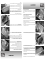
OPERATIONAL GUIDELINES
• The sander must be unplugged from the power source before
adjusting or replacing parts.
• The table lock knob must be properly tightened.
• The guards must be properly installed, adjusted and locked.
• All mobile parts must have sufficient space to move and they must
move freely.
• Make sure lock knobs and handles do not loosen during operation
(caused by vibrations).
• Wait for the sanding belt to reach full speed before sanding.
• The motor must turn counterclockwise, same for the sanding disc.
The sanding belt must travel towards the floor when in the vertical
position.
• Do not force a workpiece on any sanding surface.
• Always support your workpiece when sanding on the belt or disc.
• Do not attempt to rapidly push a corner of a workpiece against the
sanding disc or belt.
• The sanding disc or belt must be replaced when it is ripped, glazed
or frayed.
• The backstop (A) Fig.24 comes installed at the rear of the belt table
to allow a greater sanding surface on the belt but this position may
cause interference with the sanding disc during operations. To
avoid this, the backstop can be repositioned to the front of the belt
table and locked in place with lock knob (B) as shown in Fig.24.
• Always position your workpiece against the left side of the sanding
disc or else you risk letting go of the workpiece due to the upwards
force on the right side of the sanding disc.
HORIZONTAL SANDING
1. Set the belt housing in the horizontal position.
2. Use backstop to support your workpiece.
4. To sand curved surfaces, remove the end safety guard, the end
drum can be used for this operation.
BELT SANDING
1. Sanding a flat surface: Firmly hold the workpiece with both
hands; keep your fingers away from the sanding belt.
Using the backstop: The backstop is used to support and position
your workpiece during a sanding operation. Place an end of your
workpiece against the backstop, then apply it to the sanding belt.
Be very careful when sanding thin workpieces on the sanding belt.
Sanding long pieces: Do not apply too much pressure on a long
workpiece. Apply only enough pressure so that the sanding belt
removes the material.
2. Sanding curved sides: External curves must be sanded on the
flat portion of the sanding belt. Internal curves must be sanded on
the drum portion of the sanding belt.
3. End sanding: It is more pratical to end sand a long workpiece with
the sanding belt in its vertical position.
4. The workpiece must be moved equally along the sanding belt.
5. Use the miter gauge for precise work.
6. To sand a perfectly straight edge, make sure the belt table is
perfectly square with the sanding belt.
DISC SANDING
1. When sanding small flat surfaces or convex edges is needed, disc
sanding is the best way to achieve good results.
2. Move the workpiece downwards on the left side of the sanding
disc.
3. The sanding disc turns much faster and removes more of the
external edge.
4. Use the miter gauge for precise work.
MAINTENANCE
REGULAR MAINTENANCE
1. Your work space and your sander should be clean after every use.
2. Remove all accumulated dirt and dust on the sander.
3. The drums must be kept clean. Dirt on the drums will cause
tracking problems and slippage of the sanding belt.
4. The dust chute must be used to avoid major accumulation of dust
inside the sander.
5. The motor must be kept clean at all times, use a vacuum to clean.
6. Regular soap can be used to clean rubber parts, guards
and painted parts.
LUBRICATION
1. The ball bearings are permanently lubricated; they need no further
lubrication.
REQUIRED MAINTENANCE
1. The power cord must be replaced immediately if it is used, cut or
damaged.
2. Sanding disc and belt must be replaced once used. King Canada
replacement discs and belts of different grits are available at your
nearest King Canada distributor.
3. Replace all used or damaged parts before using the sander.
4. Do not attempt to repair the sander yourself, contact a qualified
technician.
Figure 24
GUIDE D’OPÉRATION
• La ponçeuse doit être débranchée lors du réglage ou du
remplacement des pièces.
• Le bouton de verrouillage de la table doit être bien serré.
• Les gardes doivent être solidement verrouillés et correctement
fixés.
• Les pièces mobiles doivent être libre de mouvement.
• Assurez-vous que les boutons ne se desserrent pas avec les
vibrations de la machine.
• Lorsque la machine est en marche attendez que la courroie
atteigne sa pleine vitesse avant de poncer.
• Le moteur doit tourner dans le sens contraire des aiguilles d’une
montre, même pour le disque de ponçage. La courroie de ponçage
doit se déplacer vers le plancher lorsque la table est en position
verticale.
• Ne tentez pas de forcer une pièce de travail sur la surface de
ponçage.
• Supportez la pièce de travail lorsque vous ponçez avec la courroie
ou le disque.
• Ne tentez pas de pousser rapidement un coin de pièce de travail
contre la courroie ou le disque.
• La surface de ponçage doit être changée lorsque glacée ou
effilochée.
• La butée d’arrêt (A) Fig.24 vient installée à l’arrière de la courroie
de ponçage pour fournir plus d’espace a effectuer vos opérations
de ponçage. Mais dans cette position, il est possible que votre
pièce de travail rentre en contact avec le boîtier du disque. Pour
empêcher le contact, il est possible de repositionner la butée
d’arrêt à l’avant de la courroie de ponçage, utilisez le bouton de
verrouillage (B) pour la fixer en place tel qu’illustré à la Fig.24.
• Il est important de seulement utiliser le côté gauche du disque de
ponçage sinon il est possible que la pièce de travail soit projectée
dans l’air.
PONÇAGE HORIZONTALE
1. Réglez le boîtier de la courroie à la position horizontale.
2. Utilisez la butée d’arrêt pour supporter votre pièce.
3. Pour ponçer des surfaces courbes, le tambour peut être utilisé
comme tambour de contact.
FINITION AVEC LA COURROIE DE PONÇAGE
1. Finition de surface plane: Tenez la pièce de travail fermement
avec les deux mains; gardez les doigts éloignés de la courroie de
ponçage.
Utilisation de la butée d’arrêt: La butée d’arrêt est utilisée pour
stabiliser et positionner la pièce durant le ponçage. Gardez les
bouts collés contre la butée d’arrêt et déplacez la pièce sur la
courroie de ponçage. Soyez très prudent lors de la finition de pièce
minces.
Finition de longue pièces: Enlevez la pression sur la pièce.
Appliquez seulement une pression suffisante pour que la courroie
de ponçage enlève le matériel.
2. Finition de côté courbés: Les courbes externes doivent être
finies sur la portion plate de la courroie de ponçage. Les courbes
intérieurs doivent être finies sur la portion du tambour de la
courroie de ponçage.
3. Finition des bouts: Il est plus pratique de finir les bouts d’une
longue pièce de travail avec la courroie de ponçage en position
verticale.
4. La pièce de travail doit être déplacé également sur la courroie.
5. Utilisez un guide à onglets pour de la précision.
6. Pour un travail en équerre, réglez l’angle de la table inclinable en
équerre avec la courroie de ponçage.
FINITION AVEC LE DISQUE DE PONÇAGE
1. Pour la finition des petites surfaces plates et des bordures
convexes, le ponçage avec le disque de ponçage est très
approprié.
2. Déplacez la pièce de travail vers le bas du côté gauche du disque
de ponçage.
3. Le disque de ponçage tourne plus rapidement et enlève plus de
matériel que la courroie de ponçage.
4. Utilisez un guide à onglets pour la précision.
MAINTENANCE
ENTRETIEN RÉGULIER
1. L’aire de travail et la machine doit être nettoyé après chaque
utilisation.
2. Retirez toutes les particules et la poussière sur la machine.
3. Les tambours doivent toujours être maintenus propres. La saleté
sur les tambours causera des problèmes d’alignement et de
glissage de la courroie.
4. Les sorties de poussière doivent êtres utilisées afin d’éviter les
accumulations de poussière dans la machine.
5. Le moteur doit être maintenu propre en tout temps, utilisez un
aspirateur.
6. La savon est recommandé pour nettoyer les pièces de
caoutchouc, les gardes de plastiques et les pièces peintes.
LUBRIFICATION
1. Les roulements à billes sont lubrifiés en permanence; ils ne
requiert pas de lubrification.
ENTRETIEN REQUIS
1. Le cordon d’alimentation doit être remplacé immédiatement
lorsqu’il est usé, coupé ou endommagé.
2. La courroie et le disque de ponçage doivent être remplacés une
fois usagés. Ces courroies et disques de ponçage sont disponibles
chez votre distributeur de produits King Canada le plus près.
3. Remplacez toute pièce usée ou endommagée avant de débuter un
travail.
4. Ne tentez pas de réparer la machine vous-même, contactez un
technicien qualifié.
Figure 24

TROUBLESHOOTING CHART
GUIDE DE DÉPANNAGE
• Motor doesn’t start.
• Voltage drop.
• Motor short circuit or bad connection.
Problem Probable cause Solution
• Check power source.
• Check all motor connections.
• Motor doesn’t start; fuse burnt,
circuit breaker tripped.
• Plug or switch short circuit.
• Motor short circuit or bad connection.
• Incompatible fuse or circuit breaker
in the electric box.
• Check plug or switch for bad
insolation or contact.
• Check all motor connections or bad
wire insolation.
• Install proper fuse or circuit breaker.
• Motor does not develop maximum
power (Voltage decrease at motor
terminal).
• The power source is overloaded
with lamps, accessories or another
motor.
• Wiring too small or circuit line too
long.
• Electrical company overload.
• Drive V-belt is tensioned incorrectly.
• Reduce charge on circuit.
• Increase wire size or reduce length
of circuit line.
• Request voltage check by power
supplier.
• Reajust V-belt tension.
• Motor overheats.
• Motor overload.
• Drive V-belt is overtensioned.
• Reduce charge on circuit.
• Retension V-belt properly.
• Motor chokes (caused by burnt
fuse or tripped circuit breaker).
• Short circuited motor or bad
connection.
• Voltage too low.
• Incompatible fuse or circuit breaker
in the electric box.
• Motor overloaded.
• Check all motor connections or bad
wire insolation.
• Rectify voltage.
• Install appropriate fuses or circuit
breaker.
• Reduce charge on circuit.
• Sander slows down during
operation.
• Applying too much pressure on the
workpiece.
• Apply less pressure.
• Sanding belt is positioned off the
top drum.
• Belt tracking is incorrect.
• Refer to manual for proper belt
tracking.
• Moteur ne démarre pas.
• Baisse de voltage.
• Circuit ouvert dans moteur ou
une mauvais contact.
Symptôme Cause possible Solution
• Vérifiez l’entrée électrique.
• Vérifiez tous les contacts sur
le moteur.
• Moteur ne démarre pas; fusible,
brûlés ou disjoncteurs sautés.
• Court circuit sur la fiche ou
l’interrupteur.
• Court circuit sur le moteur
ou mauvais contact.
• Fusibles ou disjoncteurs
incompatible dans le panneau
électrique.
• Vérifiez la fiche ou l’interrupteur
pour mauvaise isolation ou contact.
• Vérifiez tous les raccords sur le
moteur pour les mauvais contacts,
les courts circuits ou la mauvaise
isolation des fils.
• Installez les fusibles ou disjoncteurs
appropriés.
• Le moteur ne génère pas sa
puissance maximale (le voltage du
moteur diminue au terminal du
moteur).
• Le circuit électrique est surchargé
avec des lumières, accessoires
ou un autre moteur.
• Filage trop petit ou circuit
trop long.
• Surcharge générale du
fournisseur d’électricité.
• La tension de la courroie
d’entraînement est incorrecte.
• Réduisez la charge sur le circuit
électrique.
• Augmentez la grosseur du filage ou
réduisez la longueur de la ligne.
• Demandez une vérification de
voltage par le fournisseur.
• Réajustez la tension de la courroie
d’entraînement.
• Surchauffe du moteur.
• Moteur surchargé.
• Surtension sur la courroie
d’entraînement.
• Réduisez la charge sur le circuit
électrique.
• Tensionnez la courroie
d’entraînement.
• Le moteur cale (à cause de
fusibles brûlés ou de disjoncteurs
sautés).
• Court circuit sur le moteur ou
mauvais contacts.
• Voltage trop bas.
• Fusibles et disjoncteurs
incompatibles dans le panneau
électrique.
• Le moteur est surchargé.
• Vérifiez les raccorts sur le moteur
pour les mauvais contacts, les
court circuits ou la mauvaise
isolation du filage.
• Rectifiez le voltage.
• Installez les fusibles et les
disjoncteurs appropriés.
• Réduisez la charge du moteur.
• La machine ralenti durant les
opérations.
• Vous appliquez trop de pression sur
la pièce de travail.
• Appuyez moin fort.
• La courroie de ponçage se
dégage du tambour du haut.
• L’alignement est incorrecte.
• Référez au manuel pour l’alignement
de la courroie de ponçage.
-
 1
1
-
 2
2
-
 3
3
-
 4
4
-
 5
5
-
 6
6
-
 7
7
-
 8
8
-
 9
9
-
 10
10
-
 11
11
-
 12
12


dans d''autres langues
- English: King Canada KC-760L User manual
Documents connexes
Autres documents
-
Skil 3375-01 Manuel utilisateur
-
 Genesis I.C.E. GBDS450 Manuel utilisateur
-
Black & Decker BDSA100 Manuel utilisateur
-
Ryobi BD4601 Manuel utilisateur
-
-
-
General International BD7004 Manuel utilisateur
-
Delta 31-695 Manuel utilisateur
-
Hitachi SB10Y1 - Power Tools Bench Top Belt Disc Sander Manuel utilisateur
-
