Huffy Green Machine, Mini Le manuel du propriétaire
- Taper
- Le manuel du propriétaire

See back page for Customer Service Information
Consulte el reverso para Servicio de Información al Cliente
Voir pages verso pour des renseignements le service à la Clientèle
© Copyright Huffy Corporation 2017
Owner’s Manual
This manual contains important safety, assembly, operation and
maintenance information.
Please read and fully understand this manual before operation.
Save this manual for future reference.
HGM-Mini EN-AU 091916 m0358
AU
EN

2
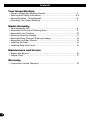
Your Green Machine
• Owner’s Model Identication Record ..................................................... 3
• Warning and Safety Information ...........................................................4-5
• Assembly Notes - Tools Needed............................................................ 6
• Operating Your Green Machine ............................................................. 7
Model Assembly
• Parts Assembly List ............................................................................... 8
• Assemble the Fork and Steering Arms .................................................. 9
• Assemble Front Cowling ....................................................................... 10
• Attaching Steering Linkage ................................................................... 11
• Assemble Rear Axle and Steering Linkage .......................................... 12
• Assemble the Rear Wheels .................................................................. 13
• Installing the Seat ................................................................................. 14
• Installing Rear Axle Cover .................................................................... 15
Maintenance and Service
• Repair and Service ............................................................................... 16
• Torque Chart ......................................................................................... 17
Warranty
• Corporation Limited Warranty ............................................................... 18
Contents

3
Green Machine
Your Bike
Owner’s Model Identication Record
NOTE: This information is only available with model itself. It is not available from Huy.
Model number is on the packaging and instruction manual.
Write the model number below to keep it for future reference.
If the model is stolen, give this number and a description of the model to the police. This
will help them nd the model.
Model Number:
Purchase Date:
Model Name:

4
Warnings and Safety
Warning and Safety Information
PLEASE READ AND FULLY UNDERSTAND THIS OWNERS MANUAL BEFORE OPERATING
THE PRODUCT
This symbol is important. See the word “CAUTION” or “WARNING” which follows it.
The word “CAUTION” is before mechanical instructions. If you do not obey these instruc-
tions, mechanical damage or failure of a part of the product can occur.
The word “WARNING” is before personal safety instructions. If you do not obey these in-
structions, injury to the rider or to others can occur.
All wheeled vehicles will provide safe, enjoyable transportation and recreation when used
and maintained properly. Like bicycling, skateboarding, and in-line skating, riding can be
dangerous even under the best of circumstances. We do not want you to get hurt. Please fol-
low all safety rules and operating instructions.
This toy should be used with caution since skill is required to avoid falls or collisions causing
injury to the user or third parties.
WARNING - TO AVOID SERIOUS INJURY:
• CHOKING HAZARD. Small parts. Not for children under 3 years.
• Adult assembly is required.
• Continuous adult supervision is required.
• The brake may be hot after continuous use. Do not touch after braking.
• Ensure rider can reach the pedals through full range of motion.
• Always wear a CPSC approved helmet while riding, with the chinstrap securely fastened.
• Always wear shoes when riding.
• Ride on smooth paved surfaces. Do not ride on streets or roadways.
• Always comply with local laws and regulations.
• Never use near motor vehicles.
• Do not ride on hills, steeply sloped areas, on or near steps, near swimming pools, or in
alleys.
• Do not ride the product at dusk, at night or at times of limited visibility.
• Do not ride o road, on grass or wet surfaces.
• Do not ride the product over curbs or bumps that can damage the steering mechanism.
• Do not wear headphones or anything else that would impair your ability to hear or see.
• Do not jump or ramp product.
• Do not tow the product.
• Do not pull any objects with the product.
• Do not push the product.
• Never ride with more than one person. Maximum weight is 50 lbs (23Kg).
• Excessive weight may cause a hazardous or unstable condition.
continued >>

5
Warnings and Safety
Warning and Safety Information - continued
• Understand all operating procedures before riding.
• Do not add a motor to the product.
• Do not modify the product.
• Before each ride check all screws, fasteners and brakes; re-tighten any that are loose.
Replace any fasteners that are damaged.
• Handlebar hand grip or tube end plugs should be replaced if damaged as bare tubes
have been known to cause injury. All products with capped handlebar ends should be
checked regularly to ensure that adequate protection for the ends of the handlebars are
in place.
• Replacement forks must have the same rake and tube inner diameter as the original
product.
• Know your limits. Be familiar with your abilities. Use common sense.
• Replace worn or broken parts immediately.
• If anything does not operate properly, discontinue use.
IF YOU HAVE ANY QUESTIONS REGARDING THE OPERATION OF THIS
PRODUCT, PLEASE REFER TO THIS OWNERS MANUAL OR CALL
CONSUMER SERVICE

6
Assembly Notes
Assembly Notes
Required Tools
Phillips Screwdriver Metric Allen Wrench (supplied)
Torque Wrench (recommended)
The instructions in this manual refer to the right and left side of the product, these are
dened from the rider position. Do not discard any parts until the unit is completely as-
sembled.

7
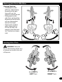
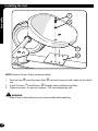
Steering your Green Machine
Leaning into a Turn
Operation
Steering Function:
• Pulling back on the
left lever, and pushing
forward on the right
lever will turn the
product towards the left.
• Pulling back on the
right lever, and pushing
forward on the left lever
will turn the product
towards the right.
• Steering this product
takes some practice.
Ensure the rider can
properly steer the prod-
uct. Practice in an open
area.
WARNING: Failure to
lean in the direction of the turn
as shown can result in the unit
rolling over.
Lean INTO a
LEFT Turn
Lean INTO a
RIGHT Turn

8
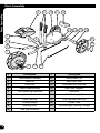
Parts Assembly
# Description # Description
1 Front Wheel Assembly 11 Rear Wheels (x2)
2 Pedal Set 12 Rear Axle Cover
3 Front Fork 13 Axle Pivot Bolt and Stop
4 Fork/Frame Bushing 14 Axle Pivot Support
5 Fork Mounting Hardware 15 Rear Axle
6 Steering Handlebar Hardware 16 Axle Bushing (x2)
7 Front Cowling 17 Axle Cap and Screw (x2)
8 Cowling Badge 18 Frame Tube
9 Steering Arms 19 Left and Right Steering Linkage
10 Seat and Hardware
98 10 11 12
1
3
4
7
182 19
17
11
5 6
161513 14
Parts Assembly

9
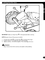
Assembly
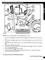
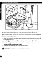
Assemble the Fork and Steering Arms
STEPS:
NOTE: Make sure Seat Bracket is pointing UP before starting.
1. Insert Fork Tube
A
fully into the Frame Tube
B
so that both Mount Holes
C
line
up.
2. Insert Pivot Shaft
D
through Frame. Place Bushings
E
on each side of Pivot Shaft
as shown.
3. Hold one Steering Arm
F
so that it is curved BACKWARDS and place on Pivot Shaft
D
.
4. Install Washer
G
and Screw
H
.
5. On opposite side, place Steering Arm
F
against Bushing
E
, making sure Steering
Arm is curved BACKWARDS.
6. Install second Washer
G
and Screw
H
.
7. Tighten both Screws
H
securely with two allen wrenches. - Make sure Steering
arms move easily back and forth.
See Torque Chart for recommended torque.
Attach Steering Linkage >>
A
B
CD
E
F
H
G
G H
F
NOTE:
Remove and set aside Bolt
from mounting hole
C
.

10
Assembly
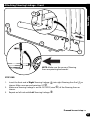
Assemble the Front Cowling
D
E
E
F
A
H
B
C
G
TIP: Rotate Wheel/Fork assembly over so that mounting hole Dimple
H
is on TOP.
NOTE: If needed, loosen Steering Arm screws during assembly, then retighten. See Torque
Chart for recommended torque.
1. Attach the Cowling
A
by sliding it down and back on the Fork so that the Cutouts
B
t around the fork legs.
2. Insert SHORT Shoulder Screw
C
down through Cowling, Frame
D
and fully inserted
Fork Tube
E
.
3. Install Screw
F
from the bottom and tighten securely with two allen wrenches. See
Torque Chart for recommended torque.
4. Snap both Cowling Badge Tabs
G
into place as shown.
CAUTION: Ensure Wheel turns smoothly without rubbing.

11
Assembly
Attaching Steering Linkage - Front
STEP ONE:
1. Insert the front end of Right Steering Linkage
A
into right Steering Arm End
C
as
shown. Make sure rear end pointing UP
D
.
2. Make sure Steering Linkage is on the OUTSIDE (view
E
) of the Steering Arms as
shown.
3. Repeat on left side with Left Steering Linkage
B
.
Proceed to next step >>
A
B
D
E
C
R
R
L
L
NOTE: Make sure the curve of Steering
Arms are pointing backwards!

12
Assembly
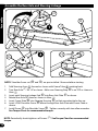
Assemble the Rear Axle and Steering Linkage
C
G
F
F
H
J
E
B
1
2
D
A
I
NOTE: Shoulder Screw set (
H
and
I
) are pre-installed. Remove before starting.
1. Fold Steering Arms
A
forward as shown with Frame Tube
B
pointing back.
2. Turn Rear Axle
C
90° UP as shown. Make sure Steering Stop
D
is on TOP as shown in
View
q
.
3. Insert each Steering Linkage End
E
into Rear Axle Plate
F
as shown.
4. Rotate Rear Axle 90° down as shown in View
w
.
5. Insert Frame Tube
B
into Steering Housing
G
so that mounting holes line up.
6. Insert LONG Shoulder Screw
H
down through Rear Axle Plate and Frame Tube as
shown.
7. Install Screw
I
into Shoulder Screw
H
. Tighten securely with two allen wrenches.
See Torque Chart for recommended torque.
NOTE: Periodically check tightness of Screws
J
. See Torque Chart for recommended
torque.

13
Assembly
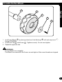
Assemble the Rear Wheels
1. Install rear Wheels
A
by placing wheel over Axle Bushings
B
with axle cap recess
C
facing OUTWARDS.
2. Install Axle Cap
D
with Screw
E
. Tighten securely. Do not over-tighten.
3. Repeat for opposite side.
WARNING:
• Ensure Wheels turn smoothly.
• The Wheels can come o if the Screws are not tight or if the screw threads are stripped.
B
A
D
C
E

14
Assembly
A
B
C
D
NOTE: Remove Screws if they are pre-installed.
1. Position Seat
A
over Mounting Plate
B
so that the correct holes align for the child’s
size.
2. Install 2 Screws
C
and Washers
D
through Seat and Mounting Plate.
3. Tighten securely. Do not over-tighten. This can damage the seat.
WARNING:
• Adjust Seat so that child can easily reach pedals while pedaling.
Installing the Seat

15
Assembly
A
C
B
D
IMPORTANT: Make sure Stop Screw
D
is fully tightened before starting.
NOTE: Remove Screws if they are pre-installed.
1. Position Axle Cover
A
over Axle Plate
B
so that the holes align.
2. Install 2 Screws
C
through Axle Cover and Axle Plate.
3. Tighten securely. Do not over-tighten. This can damage the Cover.
WARNING:
• Adjust Seat so that child can easily reach pedals while pedaling.
Installing Rear Axle Cover

16
Maintenance
Repair and Service
WARNING:
• Inspect the model frequently. Failure to inspect the model and to make repairs or
adjustments, as necessary, can result in injury to the rider or to others. Make sure all
parts are correctly assembled and adjusted as written in this manual and any “Special
Instructions”.
• Immediately replace any damaged, missing, or badly worn parts with genuine replace-
ment parts.
• Make sure all fasteners are correctly tightened as written in this manual and any “Spe-
cial Instructions”. Parts that are not tight enough can be lost or operate poorly. Over
tightened parts can be damaged. Make sure any replacement fasteners are the correct
size and type.
NOTE: Have a bike service shop make any repairs or adjustments for which you do not
have the correct tools or if the instructions in this manual or any “Special Instructions” are
not sucient for you.

17
Maintenance
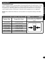
Torque Chart
Recommended Torque:
Use of a torque wrench is recommended. Recommended torque for each fastener is listed
below. In addition to tightening to the recommended torque, please ensure the parts of
the product are suciently tightened by performing the functional tests (in the compo-
nent assembly sections of the owner’s manual) on each component as it is tightened.
NOTE: Please check that all fasteners on the product are torqued according to the table
below:
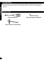
Recommended Torque for clean, dry threads: How to Measure:
Fastener Size Torque (ft-lb / N•m)
Screw or bolt size is determined
by the width at the THREADS as
shown.
.157 in (4 mm) 3.1 ft-lbs (4.2 N•m)
.196 in (5 mm) 5 ft-lbs (6.8 N•m)
.236 in (6 mm) 7 ft-lb (9.5 N•m)
.275 in (7 mm) 12 ft-lbs (16.3 N•m)
.314 in (8 mm) 17 ft-lbs (23 N•m)
.393 in (10 mm) 33 ft-lbs (44.7 N•m)

18
Huffy Warranty
Warranty
General:
• Part or model speci cations are subject to
change without notice.
• This Limited Warranty is the only warranty for
this product. There are no other expressed or
implied warranties.
• This Limited Warranty extends only to the
original consumer and is not transferable to
anyone else.
• Warranty registration is not required.
• The only uses for this product are described in
this manual.
What does this Limited Warranty cover? This
Limited Warranty covers all parts of the product
except those indicated below as not warranted.
What must you do to keep the Limited Warranty
in eff ect?
This Limited Warranty is e ective only if:
• Product is completely and correctly assembled.
• Product is used under normal conditions for its
intended purpose (see the following section for
excluded activities).
• Product receives all necessary maintenance and
adjustments.
• Product is used for general transportation and
recreational use only.
What is not covered by this Limited Warranty?
• This Limited Warranty does not cover normal
wear and tear, normal maintenance items, or
any damage, failure, or loss that is caused by
improper assembly, maintenance, adjustment,
storage, or use of the Product.
This Limited Warranty will be void if the unit is
ever:
• Used in any competitive sport
• Used for stunt riding, jumping, aerobatics or
similar activity
• Modi ed in any way
• Modi ed with the addition of a motor
• Ridden by more than one person at a time
• Rented, sold, or given away
• Used in a manner contrary to the instructions
and warnings in this Owner’s Manual
Hu y will not be liable for incidental or
consequential loss or damage, due directly or
indirectly from use of this product. Some states do
not allow the exclusion or limitation of incidental
or consequential damages, so the above limitation
may not apply to you.
What rights do you have? This warranty gives
you speci c legal rights. You may also have other
rights which vary from state to state.
What will Huff y do? Hu y will replace, without
charge to you, the component found to be
defective by Hu y.
CONTACTING CUSTOMER SERVICE:
How do you report a problem with this product
or submit a warranty claim?
• Contact Consumer Service - See included list
for Customer Contact information or visit www.
hu ybikes.com/contact.
IN AUSTRALIA:
• Warranty claims can be submitted to;
Hunter Products Pty Ltd - PH: 1800 224 094
Email: [email protected] - Level
2, 424 Warrigal Road, Moorabbin, Victoria 3189
Australia.
The following text is incorporated into this Limited
Warranty if this product was purchased in Australia
(but it is not incorporated if such product was
purchased in New Zealand):
• Our goods come with guarantees that cannot
be excluded under the Australian Consumer
Law. You are entitled to a replacement or refund
for a major failure and for compensation for any
other reasonably foreseeable loss or damage.
You are also entitled to have the goods repaired
or replaced if the goods fail to be of acceptable
quality and the failure does not amount to a
major failure.
Limited Warranty
How long does this Limited Warranty Last?
• Warranty is from date of purchase.
• Frame and all components are warranted for
six (6) months.
• Resin wheels are not warranted.

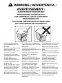
WARNING / ADVERTENCIA /
AVERTISSEMENT :
ALWAYS WEAR YOUR HELMET
WHEN RIDING THIS PRODUCT!
USE SIEMPRE EL CASCO AL MONTAR
ESTE PRODUCTO!
TOUJOURS PORTER VOTRE CASQUE LORS
DE L’UTILISATION DE CE PRODUIT !
• Helmet should sit level on
your head and low on your
forehead
• Adjust the strap sliders below
the ear on both sides.
• Buckle the chin strap. Adjust
strap until it is snug.
• No more than two ngers
should t between the strap
and your chin.
• A proper tting helmet
should be comfortable and
not rock forward/backward
or side to side.
• Always read the user manual
that comes with your helmet
to make sure it is tted and
attached properly to the
wearer’s head according
to the tting instructions
described in the user manual.
• El nivel del casco se debe ajustar
sobre su cabeza y cubrir su frente
hasta abajo.
• Ajuste la correa controles
deslizantes por debajo de la oreja
en ambos lados.
• Hebille el barboquejo. Ajustar
la tira hasta que quede bien
ajustado.
• Solamente deben caber dos
dedos entre la correa y la barbilla.
• El uso de un casco a su medida
debe de ser cómodo y no estar
moviéndose hacia delante o
hacia atrás o de lado a lado.
• Siempre lea el manual del
usuario que viene con su casco
para asegurarse de que se
encuentra instalado y conectado
correctamente a la cabeza
de acuerdo con el manual de
montaje se describe en el manual
del usuario.
• Casque doit reposer sur la tête
en étant rabaissé sur le front
• Régler la glissière de courroie
au-dessous de l’oreille des deux
côtés.
• Boucle de la jugulaire. Régler
l’attache jusqu’à ce qu’elle soit
serrée.
• L’espace entre le menton et
la courroie ne doit pas être
supérieur à deux doigts.
• Un casque adapté doit être
confortable et ne pas se
déplacer vers l’arrière ou les
côtés.
• Toujours lire le manuel
d’utilisation fourni avec votre
casque pour s’assurer qu’il est
monté et xé correctement
à la tête du porteur selon les
instructions de montage du
manuel de l’utilisateur.

[ In the US ]
PLEASE - BEFORE RETURNING TO STORE,
CONTACT HUFFY CUSTOMER SERVICE. WE
ARE GLAD TO ASSIST YOU WITH ANY PARTS
OR ASSEMBLY PROBLEMS YOU MIGHT
HAVE!
For Fast Customer Service, go to:
http://www.huff ybikes.com/contact
To Order Parts (US only), go to:
http://www.huff ybikes.com/parts
OR TEL: 1 800 872 2453 (US only)
For email, go to http://www.huff ybikes.com/contact
[ CANADA ]
VEUILLEZ NOTER : AVANT DE
RETOURNER AU MAGASIN,
COMMUNIQUEZ AVEC LE SERVICE
À LA CLIENTÈLE DE HUFFY. NOUS
VOUS AIDERONS VOLONTIERS AVEC
TOUT PROBLÈME CONCERNANT LES
PIÈCES OU LE MONTAGE!
Pour un Service à la clientèle rapide, allez sur le
site :
http://www.huff ybikes.com/contact
To Order Parts (CANADA only), go to:
http://www.huff ybikes.com/parts
OU appelez le 1 800 872 2453
(CANADA only)
Pour communiquer par courriel
hu ycanada@hu y.com
[ MÉXICO ]
ANTES DE DEVOLVER EL
PRODUCTO A LA TIENDA,
COMUNÍQUESE CON SERVICIO
AL CLIENTE DE HUFFY. NOS
COMPLACE AYUDARLO CON
CUALQUIER PARTE O PROBLEMA
DE ENSAMBLADO QUE PUDIERA
TENER.
Para obtener Servicio al cliente rápido, visite:
http://www.huff ybikes.com/
O LLAME AL TEL: 01800 1483 391
(Mexico only)
Para comunicarse por correo electrónico:
servicio@hu ymex.com
H-Tri_STOP-Global_022217_i0388
Check http://www.huff ybikes.com/home/globalcontact
for the current contact information
http://www.huff ybikes.com/home/globalcontact
para obtener la información de contacto actual
Véri er http://www.huff ybikes.com/home/globalcontact
pour les informations de contact actuelles
-
 1
1
-
 2
2
-
 3
3
-
 4
4
-
 5
5
-
 6
6
-
 7
7
-
 8
8
-
 9
9
-
 10
10
-
 11
11
-
 12
12
-
 13
13
-
 14
14
-
 15
15
-
 16
16
-
 17
17
-
 18
18
-
 19
19
-
 20
20


Huffy Green Machine, Mini Le manuel du propriétaire
- Taper
- Le manuel du propriétaire
dans d''autres langues
Documents connexes
-
Huffy 28689 Le manuel du propriétaire
-
-
-
-
-
-
-
-