
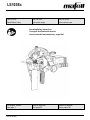
LS103Ec
170762.0822/b
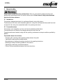
IMPORTANT
Read Before Using
IMPORTANT
Lire avant usage
IMPORTANTE
Leer antes de usar
Operating/Safety Instructions
Consignes d’utilisation/de sécurité
Instrucciones de funcionamiento y seguridad
For English Version
See page 2
Version française
Voir page 20
Versión en español
Ver la página 39

LS103Ec
2
08/2022
English
Table of contents
1 Signs and symbols ........................................................................................................... 3
1.1 Identification of the device ................................................................................................ 5
2 Product specifications ...................................................................................................... 5
2.1 Technical data .................................................................................................................. 5
2.2 Scope of delivery .............................................................................................................. 6
2.3 Adjustment elements ........................................................................................................ 6
3 General safety .................................................................................................................. 7
3.1 Intended use ..................................................................................................................... 7
3.2 Foreseeable misuse ......................................................................................................... 7
3.3 Safety instructions ............................................................................................................ 8
3.4 Specific safety rules ......................................................................................................... 9
3.5 Safety devices ................................................................................................................ 10
3.6 Residual risks ................................................................................................................. 11
4 Setup / adjustment ......................................................................................................... 11
4.1 Mains connection ........................................................................................................... 11
4.2 Routing of the connecting cable ..................................................................................... 11
4.3 Mounting the cutting chain assembly ............................................................................. 12
5 Operation ........................................................................................................................ 14
5.1 Startup ............................................................................................................................ 14
5.2 Switching on / off ............................................................................................................ 14
5.3 Transverse guide fence adjustment ............................................................................... 15
5.4 Mortise depth adjustment ............................................................................................... 15
5.5 Working information ....................................................................................................... 16
5.6 Mortising recesses ......................................................................................................... 16
6 Service and maintenance ............................................................................................... 17
6.1 Chain cutters .................................................................................................................. 17
6.2 Storage ........................................................................................................................... 17
7 Troubleshooting .............................................................................................................. 18
8 Optional accessories ...................................................................................................... 19
9 Exploded view and spare parts list ................................................................................. 19

LS103Ec
08/2022
3
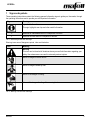
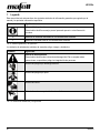
1 Signs and symbols
These operating instructions contain the following general information signs to guide you, the reader, through
the operating instructions and to provide you with important information.
Sign
Meaning
Important information
This sign highlights user tips and other useful information.
➢
Identifies an intermediate result in a sequence of actions.
✓
Identifies the final result of a sequence of actions.
Tab. 1: General signs and their meanings
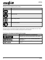
Warning icons warn of dangerous points, risks and obstacles.
Icon
Meaning
Warning
This icon can be found at all locations where you can find information regarding your
safety. Non-observance can result in extremely serious injuries.
Warns of danger of electric shock.
Warns of danger caused by dust.
Warns of the danger of cutting.
Warns of the danger of cutting off or severing limbs.
Tab. 2: Warning icons and their meanings

LS103Ec
4
08/2022
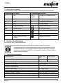
Mandatory icons are intended to prevent accidents.
Icon
Meaning
Wear eye protection.
Wear dust mask.
Wear hearing protection.
Wear protective gloves.
Tab. 3: Mandatory icons and their meanings
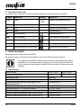
During the operation of the power tool there are always actions to be taken where hazards can occur. These
potentially dangerous actions are preceded by warnings which must be observed.
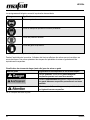
Classification of the danger level (signal words) of warnings
Warning
Meaning and consequences of non-observance
Imminent danger that will cause serious or fatal injuries.
Potentially dangerous situation that can cause serious or
fatal injuries.
Potentially dangerous situation that can cause minor
injuries.
Tab. 4: Structure of warnings

LS103Ec
08/2022
5
1.1 Identification of the device
The icons listed and explained below can be found on the rating plate or on the product.
Symbol
Explanation
Symbol
Explanation
V
Volt
1, 2, 3, ...
I, II, III, ...
Rotational speed setting
A
Ampere
rpm
Revolutions per minute
Hz
Hertz
ø
Saw blade diameter
W
Watt
~
Alternating current
kg
Kilogram (weight)
Protection class II
min
Minutes (time)
Read operating instructions
s
Seconds (time)
Protective goggles
n0
Rated speed at no load
Hearing protection
n
Rated speed at normal load
Dust mask
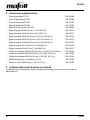
2 Product specifications
for machines with item number 924222
The article number and machine number are listed on the type plate of the machine.
By entering the article number and machine number on the MAFELL homepage, you can
call up the spare parts lists, exploded drawings, and other product information belonging
to your machine (see also Chapter 9 Exploded view and spare parts list).
2.1 Technical data
Universal motor
120 V~, 60 Hz
240 V~, 60 Hz
Current at normal load
20 A
13 A
Rotational speed at no-load operation
4050 rpm
Mortise depth
100 mm [3.94 in]
Mortise depth with guide rack FG 150 (special accessories)
150 mm [5.91 in]
Weight without power cord
8.7 kg [19.18 lbs]
Weight of guide rack FG 150 (special accessories)
4.6 kg [10.14 lbs]
Dimensions (width x length)
300 x 420 mm [11.81 x 16.54 in]
Height with cutting chain assembly 100 mm [3.94 in]
365 mm [14.37 in]
Height with cutting chain assembly 150 mm [5.91 in]
415 mm [16.34 in]

LS103Ec
6
08/2022
2.2 Scope of delivery
Fig. 1: Scope of delivery
Components
A
Light voltage chain mortiser with:
- chain guard
- cutting chain
- sprocket wheel
- guide rail
- two handles
B
Transverse guide fence
C
Allen key 4 mm [0.16 in]
D
Allen key 8 mm [0.32 in]
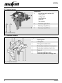
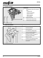
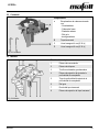
2.3 Adjustment elements
Fig. 2: Adjustment elements
Adjustment elements on the machine
1
Operating lever
2
Locking lever
3
Chain guard knurled screws
4
Mortise depth adjustment clamping lever
5
Mortise depth adjustment depth stop
6
Guide rail
7
Transverse guide fence scale
8
Transverse guide fence clamping lever

LS103Ec
08/2022
7
3 General safety
Please read all safety instructions and directions. Failure to comply with the safety instructions and
directions can cause electric shock, fire and/or serious injuries. Please retain all safety instructions and
directions for future reference.
3.1 Intended use
The machine is designed exclusively for mortising solid wood, using cutting chains.
The dimensions of the chain cutter assemblies (guide rail, cutting chain and sprocket wheel) used here must
correspond to the cutting chain assemblies listed in the operating instructions.
3.2 Foreseeable misuse
The machine is not intended for any other use than the intended use listed above.
The manufacturer is not liable for any damage resulting from such other use.
To use the machine as intended, comply with the operating, maintenance and repair conditions specified by
MAFELL.
Foreseeable misuse also includes:
- Tampering with, removing and/or bypassing safety devices of any kind.
- Operating the machine without safety devices.
- Non-observance of safety and warning instructions in the operating instructions.
- Removing the safety and warning labels from the machine.
- Operating the machine by unauthorized persons.
- Failure to follow prescribed maintenance and care instructions.

LS103Ec
8
08/2022
3.3 Safety instructions
READ ALL INSTRUCTIONS!
Non-observance of the instructions listed below can cause electric shock, fire and/or serious injuries
.
Work area
- Children and adolescents are not allowed to operate this machine.
- When using the machine outdoors, the use of an earth leakage circuit breaker is recommended.
- Replace damaged cables or plugs immediately. To avoid safety hazards, only MAFELL or an authorized
MAFELL service workshop is allowed to replace parts.
- Prevent sharp kinks of the cable. Do not wrap the cable around the machine, especially when transporting
and storing the machine.
- Do not use this machine when you are tired, or under the influence of drugs, alcohol or medicaments. Be
aware of what you are doing. Stay alert and use common sense.
- Keep children and bystanders at a distance while you are operating the machine. Distractions can cause
you to lose control of the machine.
- Use eye protection, dust mask and hearing protection. Appropriate safety equipment, used
under proper conditions, will reduce the risk of injuries.
Instructions for service and maintenance:
- Cleaning the machine regularly, especially the adjustment elements and the guiding devices, is an important
safety factor.
- Ensure that only genuine MAFELL spare parts and accessories are used. Failure to do so will make
warranty claims and the liability of the manufacturer null and void.
- Wear protective gloves during all maintenance and servicing work.
- Prepare a periodic maintenance schedule for your machine. When you clean the machine, be careful
not to disassemble any part of the machine. Reassembling the machine bears the risk that internal
wires are routed incorrectly or pinched, or that return springs of the safety device are mounted
incorrectly. Certain cleaning agents, such as gasoline, carbon tetrachloride, ammonia, etc. can damage
plastic parts.
- Some of the dust produced by sawing, sanding, drilling and other building work contains chemicals
known to cause cancer, birth defects or other reproductive harm. Some examples of these
chemicals are:
- Lead from lead-based paints,
- Crystalline silica from bricks and cement and other masonry products,
- Arsenic and chromium from chemically treated wood.
Your risk from this hazard varies with the frequency at which you perform this type of work. To reduce your
exposure to these chemicals: Work in a well-ventilated area. Work only with approved safety equipment,
such as dust masks that are specially designed to filter out particles of microscopic size.

LS103Ec
08/2022
9
3.4 Specific safety rules
Sawing method
- Ensure that you stand in an unobstructed and non-slip area with adequate lighting.
- Always pull out the power plug before you change tools, make adjustments, or eliminate malfunctions (this
also includes removing trapped chips).
- Never work on workpieces that are too small or too large for the machine capacity.
- Mount cutting chain and guide rail properly and keep them in order. Prior to reusing a defective cutting
chain, repair it properly. Use only sharp cutting chains!
- Use only type 100 cutting chain assemblies for a machine without FG 150 guide rack!
- Remove the chain guard only for tool change. Screw it back on immediately afterwards. Never work without
chain guard!
- Never transport the chain mortiser with cutting chain running. Avoid any contact of the running cutting chain
with the soil!
- Never clamp the switch.
- Prior to switching on the machine check to ensure that the cutting chain is properly tensioned.
- Whenever possible, secure the workpiece, for example with screw clamps, against swinging away, slipping,
tipping over or bobbing up.
- Do not start mortising the workpiece before the cutting chain has reached its full rotational speed.
- Check the workpiece for foreign bodies. Never mortise into metal parts, such as nails.
- Hold the machine with both hands before you switch it on.
- Switch on the machine only when there is not contact between the cutting chain and the workpiece. Position
the machine for mortising when the cutting chain is running.
- While you are mortising, ensure that the connecting cable always runs towards the rear, away from the
machine.
- Adjust the mortising feed rate to the material thickness. Mortising too quickly will overload the motor, results
in improper mortises, and causes the cutting chain to be blunt more quickly.
- Do not remove the machine from the workpiece before the cutting chain has stopped.
- Never reach into the chip ejector and into the unprotected area of the cutting chain while the machine is
running.
- Before switching on the machine during freehand milling, make sure that the transverse guide fence is
fastened and is in contact with the workpiece. Do not mill without the transverse guide fence!
- Only use the machine outdoors or in well ventilated rooms.
RETAIN THESE INSTRUCTIONS!

LS103Ec
10
08/2022
3.5 Safety devices
Danger
Risk of injury from missing safety devices
These devices are necessary for the safe operation of the machine. They must
not be removed or rendered ineffective.
➢ Check the proper functioning of the safety devices before you start
operating the machine.
➢ Never use the machine with missing or ineffective safety devices.
The machine is equipped with the following safety devices:
Safety device
Type of check
Handles
Visual check for damage
Hose connector
Visual check for damage and obstruction
If the safety devices are damaged or not functioning properly, follow the instructions in the chapter
Troubleshooting. For other malfunctions, please contact your dealer or MAFELL Customer Service directly.

LS103Ec
08/2022
11
3.6 Residual risks
Warning
Risk of injury when working with the machine
Even when the machine is used as intended and in compliance with the safety
regulations, there are still residual risks caused by the intended use, which can
have consequences for your health.
➢ Observe the safety instructions and information in these instructions.
➢ Always be extremely careful and cautious when you work with the machine.
The existing residual risks include:
- Touching the cutting chain in the open section.
- Touching the cutting chain above the workpiece during the mortising process.
- Touching the part of the cutting chain protruding below the workpiece when you are mortising through the
workpiece.
- Touching the cutting chain from the side.
- Breaking cutting chain.
- Backlash of the machine against the user if the transverse guide fence is not fixed during freehand milling.
- Impaired hearing when working without hearing protection for long periods of time.
- Emission of harmful wood dusts during longer operation without extraction.
4 Setup / adjustment
4.1 Mains connection
Prior to starting up the machine, check to ensure that the mains voltage corresponds to the operating voltage
specified on the rating plate of the machine.
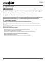
4.2 Routing of the connecting cable
Warning
Electric shock when cutting into the connecting cable
The connecting cable can impair safety functions and work functions and
get into contact with the cutting tool. Cutting into the connecting cable of
the machine puts the metal parts of the machine under tension and
causes an electric shock. There is a risk of injury for the user.
➢ When working, pay attention to the way the connecting cable is
routed.
➢ Never cut into the connecting cable of your machine.

LS103Ec
12
08/2022
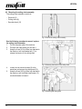
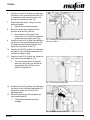
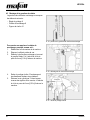
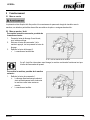
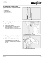
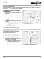
4.3 Mounting the cutting chain assembly
The cutting chain assembly consists of:
- Guide rail (6)
- Cutting chain (9)
- Sprocket wheel (10)
Fig. 3: Parts of the cutting chain assembly
Use the following procedure to mount / replace
the cutting chain assembly:
1. Pull out the power plug of the machine.
2. Put down the cable where you can see it.
3. Using the 4-mm [0.16-in] Allen key attached to
the machine, turn the threaded pin (11) to
release the tension of the cutting chain.
Fig. 4: Releasing the tension of the cutting chain
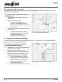
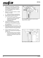
4. Loosen the two knurled screws (3) at the
same time and remove the chain guard (12).
5. Using the 8-mm [0.32-in] Allen key attached to
the machine, turn the fillister head screw (13)
counterclockwise to loosen it.
Fig. 5: Removing the chain guard

LS103Ec
08/2022
13
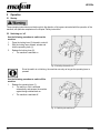
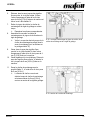
6. Using the 4-mm [0.16-in] Allen key attached to
the machine, turn the countersunk screw (14)
in the gearbox shaft counterclockwise, and
remove the countersunk screw (14).
7. Remove sprocket wheel, cutting chain and
guide rail together.
➢ Replace the corresponding parts.
8. Mount the cutting chain together with the
sprocket wheel and the guide rail.
➢ Ensure that the cutting teeth of the
cutting chain run in the working direction
(see arrows on the chain guard (12)).
9. Using the 4-mm [0.16-in] Allen key attached to
the machine, turn the countersunk screw (14)
in the gearbox shaft counterclockwise, and
tighten the countersunk screw (14).
10. Using the 8-mm [0.32-in] Allen key attached to
the machine, turn the fillister head screw (13)
clockwise to tighten it lightly.
Fig. 6: Installing and removing sprocket wheel, cutting
chain and guide rail
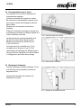
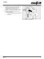
11. Using the 4-mm [0.16-in] Allen key, tighten the
chain cutter at the threaded pin (11).
➢ The correct chain tension is reached
when the cutting chain can be lifted by
approximately 6 mm [0.24 in] at the
middle of the guide rail.
Fig. 7: Tensioning the cutting chain
12. Using the 8-mm [0.32-in] Allen key attached to
the machine, turn the fillister head screw (13)
clockwise to tighten it at the end of the
adjustment work.
13. Mount the chain guard (12) and tighten the
two knurled screws (3).
✓ Cutting chain assembly mounted /
changed.
Fig. 8: Mounting the chain guard

LS103Ec
14
08/2022
5 Operation
5.1 Startup
These operating instructions must be brought to the attention of all persons entrusted with the operation of the
machine, with particular emphasis on the chapter "Safety instructions".
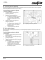
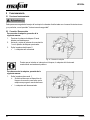
5.2 Switching on / off
Use the following procedure to switch on the
machine:
1. Press the locking lever (2) forward to unlock it.
2. With the locking lever pressed, actuate and
hold the operating lever (1).
3. Release the locking lever (2).
✓ The machine is switched on
Fig. 9: Switching the machine on
Since the switch is not latching, the machine runs only as long as the operating lever is
pressed.
Use the following procedure to switch off the
machine:
1. Release the operating lever (1).
➢ The switch-on lock is activated
automatically and secures the machine
against being switched back on.
✓ The machine is switched off.
Fig. 10: Switching the machine off

LS103Ec
08/2022
15
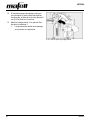
5.3 Transverse guide fence adjustment
The transverse guide fence permits the distance between the tenon hole and the exterior side to be adjusted
continuously between 8 and 150 mm [0.31 - 5.90 in].
Use the following procedure to adjust the
transverse guide fence:
1. Loosen the clamping lever (8) for the
transverse guide fence.
2. Adjust the transverse guide fence.
➢ The distance is indicated on the scale
(7). Observe the indicator edge, it
depends on the hole width 30, 35 or
40 mm!
3. Tighten the clamping lever (8) for the
transverse guide fence.
➢ The clamping lever is adjustable. Pull it
upwards to move it to the required
clamping position.
✓ Transverse guide fence adjusted.
Fig. 11: Adjusting the transverse guide fence
5.4 Mortise depth adjustment
The mortise depth can be adjusted continuously. The mortising depth depends on the currently used chain
cutter assembly.
Use the following procedure to adjust the
mortise depth:
1. Loosen the clamping lever (4) for the mortise
depth adjustment.
2. Using a meter stick, adjust the depth stop (5)
to the required depth.
3. Tighten the clamping lever (4) for the mortise
depth adjustment.
➢ The clamping lever is adjustable. Pull it
upwards to move it to the required
clamping position. Do not set the
clamping lever in the mortise direction!
✓ Mortise depth adjusted.
Fig. 12: Adjusting the mortise depth

LS103Ec
16
08/2022
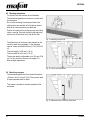
5.5 Working information
To mortise, hold the machine at both handles.
The transverse guide fence must be in contact with
the workpiece.
Do not start mortising the workpiece before the
cutting chain has reached its full rotational speed.
Mortise at uniform pressure and feed rate.
Position the machine for mortising when the cutting
chain is running. Start with mortising the beginning
and the end of the tenon hole, then do the rest.
Fig. 13: Mortising a tenon hole
The dimensions of the tenon holes depend on the
currently used chain assembly. In the standard
version, these are 28x40x100 mm [1.10x1.57x3.94
in].
The hole length L is 28 mm [1.10 in].
The hole width W is 40 mm [1.57 in].
The mortise depth is adjustable up to 100 mm [3.94
in]. For this, see the information in chapter 5.4
Mortise depth adjustment.
Fig. 14: Tenon hole dimensions
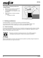
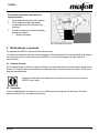
5.6 Mortising recesses
The transverse guide fence has several boreholes
(15) with a ø of 4.5 mm [0.18 in]. They can be used
to secure wooden slats on them.
This makes it possible to mortise recesses at the
workpiece.
Fig. 15: Boreholes at the transverse guide fence

LS103Ec
08/2022
17
Use the following procedure to produce a
recess:
1. Define the distance required for the recess.
2. Attach an appropriately sized wooden slat at
the boreholes on the transverse guide fence.
3. Position the machine on the workpiece and
mortise the recess.
✓ Recess produced.
Fig. 16: Mortising a recess
6 Service and maintenance
MAFELL machines are of a low-maintenance design.
The installed ball bearings are lubricated for life. After a longer period of operation, MAFELL recommends that
the machine be handed over to an authorized MAFELL service workshop for inspection.
6.1 Chain cutters
After two hours of operation, the cutting chain should be cleaned and lubricated in a bath with thin-bodied oil.
This requires the cutting chain to be removed. For this, see the information in chapter 4.3 Mounting the cutting
chain assembly.
Replace a blunt cutting chain or have a blunt cutting chain sharpened in a MAFELL
Customer Service workshop.
6.2 Storage
Clean the machine thoroughly if you will not use it for quite some time. Spray bare metal parts with a rust
inhibitor.

LS103Ec
18
08/2022
7 Troubleshooting
Warning
Risk of injury from a sudden start of the machine.
There is a risk that the machine starts suddenly due to carelessness when
working with the machine or during troubleshooting. The rotating saw blade can
cause serious injuries.
➢ Determining the causes of existing malfunctions and their elimination
always require increased attention and caution!
➢ Pull out the mains plug before you start troubleshooting!
Some of the most common malfunctions and their causes are listed below. For other malfunctions, please
contact your dealer or MAFELL Customer Service directly.
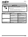
Malfunction
Cause
Elimination
Machine can not be switched on
Mains voltage missing or too low
Have the power supply checked
by an electrician
Mains fuse defective
Have the fuse replaced by an
electrician
Carbon brushes worn out
Take the machine to the MAFELL
customer service workshop
Machine stops during the cutting
process
Mains failure
Have the mains back-up fuses
checked by an electrician
Machine overload
Reduce feed rate
Carbon brushes worn out
Take the machine to the MAFELL
customer service workshop
Chip ejector obstructed
Wood too damp
Clean chip ejector

LS103Ec
08/2022
19
8 Optional accessories
- Guide rack FG 150
Order no. 200980
- Slitting device SG 230
Order no. 200990
- Slitting device SG 400
Order no. 201000
- Slitting device SG 500
Order no. 201005
- Clamping device (for SG 400)
Order no. 039602
- Guide rail 28x40x100 mm [1.10x1.57x3.94 in]
Order no. 091010
- Guide rail 28x40x150 mm [1.10x1.57x5.91 in]
Order no. 091011
- Guide rail 28x30/35x100 mm [1.10x1.18/1.38x3.94 in]
Order no. 091012
- Guide rail 28x30/35x150 mm [1.10x1.18/1.38x5.91 in]
Order no. 091013
- Guide rail 30x30/35x100 mm [1.18x1.18/1.38x3.94 in]
Order no. 091014
- Guide rail 28x1.5x150 mm [1.10x0.06x5.91 in]
Order no. 091016
- Guide rail 28x2x150 mm [1.10x0.08x5.91 in]
Order no. 091017
- Cutting chain 28x35/40/50x100 mm [1.10x1.38/1.57/1.97x3.94 in]
Order no. 091224
- Cutting chain 28x35/40x100 mm [1.10x1.38/1.57x3.94 in]
Order no. 091230
- Cutting chain 28x35/40x150 mm [1.10x1.38/1.57x5.91 in]
Order no. 091234
- Spare links + rivet 28 mm [1.10 in]
Order no. 091279
- Sprocket wheel 28x35/40 mm [1.10x1.38/1.57 in]
Order no. 091683
9 Exploded view and spare parts list
The corresponding information on the spare parts can be found on our homepage: www.mafell.com

LS103Ec
20
08/2022
Français
Sommaire
1 Explication des pictogrammes ........................................................................................ 21
1.1 Identification de l'appareil ............................................................................................... 23
2 Données caractéristiques ............................................................................................... 23
2.1 Caractéristiques techniques ........................................................................................... 23
2.2 Équipement standard ..................................................................................................... 24
2.3 Éléments de commande ................................................................................................. 24
3 Sécurité générale ........................................................................................................... 25
3.1 Utilisation conforme ........................................................................................................ 25
3.2 Utilisation non conforme prévisible ................................................................................. 25
3.3 Consignes de sécurité .................................................................................................... 26
3.4 Consignes de sécurité spécifiques ................................................................................. 27
3.5 Dispositifs de sécurité .................................................................................................... 28
3.6 Risques résiduels ........................................................................................................... 29
4 Équipement / Réglage .................................................................................................... 29
4.1 Raccordement au réseau ............................................................................................... 29
4.2 Pose du câble de raccordement ..................................................................................... 29
4.3 Montage de la garniture de chaîne ................................................................................. 30
5 Fonctionnement .............................................................................................................. 33
5.1 Mise en service .............................................................................................................. 33
5.2 Mise en marche / Arrêt ................................................................................................... 33
5.3 Réglage de la butée transversale ................................................................................... 34
5.4 Réglage de la profondeur de mortaisage ....................................................................... 34
5.5 Recommandations pour le travail ................................................................................... 35
5.6 Mortaisage d'évidements ................................................................................................ 35
6 Entretien et maintenance ............................................................................................... 36
6.1 Chaînes de mortaisage .................................................................................................. 36
6.2 Stockage ........................................................................................................................ 36
7 Élimination des défauts .................................................................................................. 37
8 Accessoires supplémentaires ......................................................................................... 38
9 Schéma éclaté et liste de pièces de rechange ............................................................... 38
La page est en cours de chargement...
La page est en cours de chargement...
La page est en cours de chargement...
La page est en cours de chargement...
La page est en cours de chargement...
La page est en cours de chargement...
La page est en cours de chargement...
La page est en cours de chargement...
La page est en cours de chargement...
La page est en cours de chargement...
La page est en cours de chargement...
La page est en cours de chargement...
La page est en cours de chargement...
La page est en cours de chargement...
La page est en cours de chargement...
La page est en cours de chargement...
La page est en cours de chargement...
La page est en cours de chargement...
La page est en cours de chargement...
La page est en cours de chargement...
La page est en cours de chargement...
La page est en cours de chargement...
La page est en cours de chargement...
La page est en cours de chargement...
La page est en cours de chargement...
La page est en cours de chargement...
La page est en cours de chargement...
La page est en cours de chargement...
La page est en cours de chargement...
La page est en cours de chargement...
La page est en cours de chargement...
La page est en cours de chargement...
La page est en cours de chargement...
La page est en cours de chargement...
La page est en cours de chargement...
La page est en cours de chargement...
La page est en cours de chargement...
-
 1
1
-
 2
2
-
 3
3
-
 4
4
-
 5
5
-
 6
6
-
 7
7
-
 8
8
-
 9
9
-
 10
10
-
 11
11
-
 12
12
-
 13
13
-
 14
14
-
 15
15
-
 16
16
-
 17
17
-
 18
18
-
 19
19
-
 20
20
-
 21
21
-
 22
22
-
 23
23
-
 24
24
-
 25
25
-
 26
26
-
 27
27
-
 28
28
-
 29
29
-
 30
30
-
 31
31
-
 32
32
-
 33
33
-
 34
34
-
 35
35
-
 36
36
-
 37
37
-
 38
38
-
 39
39
-
 40
40
-
 41
41
-
 42
42
-
 43
43
-
 44
44
-
 45
45
-
 46
46
-
 47
47
-
 48
48
-
 49
49
-
 50
50
-
 51
51
-
 52
52
-
 53
53
-
 54
54
-
 55
55
-
 56
56
-
 57
57


