Panasonic CSMZ16XKE Mode d'emploi
- Catégorie
- Climatiseurs split-system
- Taper
- Mode d'emploi

Deutsch Español Français English
ACXF55-29741
Operating Instructions
Air Conditioner
Model No.
Indoor Unit Outdoor Unit
CS-Z20XKEW
CS-Z25XKEW
CS-Z35XKEW
CS-Z42XKEW
CS-Z50XKEW
CS-Z71XKEW
CS-XZ20XKEW
CS-XZ25XKEW
CS-XZ35XKEW
CS-XZ50XKEW
CS-MZ16XKE
Single Split
CU-Z20XKE
CU-Z25XKE
CU-Z35XKE
CU-Z42XKE
CU-Z50XKE
CU-Z71XKE
Multi Split
CU-2Z35TBE
CU-2Z41TBE
CU-2Z50TBE
CU-3Z52TBE
CU-3Z68TBE
CU-4Z68TBE
CU-4Z80TBE
CU-5Z90TBE
Operating Instructions
Air Conditioner
2-25
Before operating the unit, please read these operating
instructions thoroughly and keep them for future reference.
Before installation, the installer should:
Read the Installation Instructions, then request the customer
keep them for future reference.
Remove the remote control packed with the indoor unit.
Comment utiliser l’appareil
Climatiseur
26-49
Avant d’utiliser l’appareil, veuillez lire ce mode d’emploi dans
son intégralité et conservez-le pour toute référence ultérieure.
Avant de commencer l’installation, l’installateur doit:
Lire les instructions d’installation, puis demander au client de
les conserver pour plus tard.
Retirer la télécommande fournie avec l’unité intérieure.
Instrucciones de funcionamiento
Climatizador de aire
50-73
Antes de utilizar la unidad, sírvase leer atentamente estas
instrucciones de funcionamiento y conservarlas para futuras
consultas.
Antes de la instalación, el instalador debe:
Lea las Instrucciones de instalación y pida al cliente que las
conserve para futuras consultas.
Retire el mando a distancia incluido con la unidad interior.
Bedienungsanleitung
Klimagerät
74-97
Bevor Sie das Gerät in Betrieb nehmen, lesen Sie bitte diese
Bedienungsanleitung aufmerksam durch und bewahren Sie
sie als künftige Referenz auf.
Vor der Installation sollte der Installateur Folgendes tun:
Die Installationsanleitung lesen und den Kunden bitten, diese
als künftige Referenz aufzubewahren.
Die in der Verpackung des Innengeräts enthaltene
Fernbedienung entfernen.

2
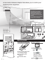
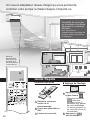
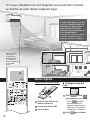
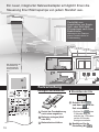
A new built-in Network Adaptor that allows you to control your
heatpump from anywhere.
Use the remote
control within 8 m
from the remote
control receiver
on the indoor unit.
Quick Guide
Flexibility to connect
Single Split System or
Multi Split System Air
Conditioner to suit your
needs.
For complete product features,
please refer to catalogue.
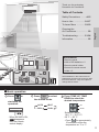
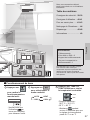
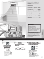
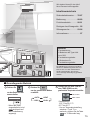
Inserting the batteries
1
2
3
1
Pull out the back cover
of remote control.
2
Insert AAA or R03
batteries.
3
Close the cover.
A
Clock setting
1
Press
CLOCK
, then
press
to set the
time
.
• Press
CLOCK
for
approximately 5
seconds to show
the time as 12-hour
(am/pm) or 24-hour.
2
Press to confi rm.
B
A

3
English
Table of Contents
Safety Precautions
……
4-15
How to Use
…………………
16-17
To Learn More
…………
18-19
Cleaning the
Air Conditioner
………………
20
Troubleshooting
…………
21-24
Information………………… 25
Accessories
• Remote control
• AAA or R03 batteries × 2
• Remote control holder
• Screws for remote control
holder × 2
The illustrations in this manual are for
explanation purposes only and may differ
from the actual unit. They are subject to
change without notice.
B
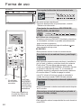
Basic operation
Thank you for purchasing
Panasonic Air Conditioner.
1
Press
to
start/stop the
operation.
POWER
•
When the unit is ON,
disappears
from the remote
control display.
3
Press TEMP UP, TEMP
DOWN to select the
desired temperature.
Up
Down
Selection range:
16.0 °C ~ 30.0 °C /
60 °F ~ 86 °F.
•
Press for approximately
10 seconds to show the
temperature as °C or °F.
2
Press
to select
the desired mode.
DRY
AUTO HEAT
COOL

4
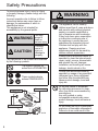
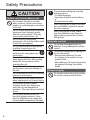
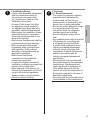
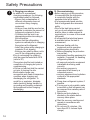
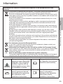
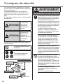
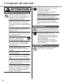
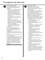
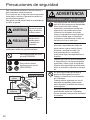
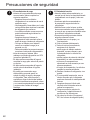
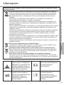
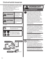
Safety Precautions
To prevent personal injury, injury to others
or property damage, please comply with the
following:
Incorrect operation due to failure to follow
instructions below may cause harm or
damage, the seriousness of which is
classifi ed as below:
This appliances is not intended for
accessibility by the general public.
WARNING
This sign
warns of
death or
serious injury.
CAUTION
This sign
warns of
injury or
damage to
property.
The instructions to be followed are classifi ed
by the following symbols:
This symbol denotes an
action that is PROHIBITED.
These symbols denote
actions COMPULSORY.
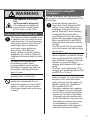
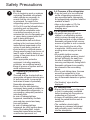
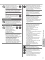
WARNING
Indoor unit and outdoor unit
This appliance can be used by
children aged from 8 years and above
and persons with reduced physical,
sensory or mental capabilities or
lack of experience and knowledge
if they have been given supervision
or instruction concerning use of
the appliance in a safe way and
understand the hazards involved.
Children shall not play with the
appliance. Cleaning and user
maintenance shall not be made by
children without supervision.
Please consult authorised dealer or
specialist to clean the internal parts,
repair, install, remove, disassemble
and reinstall the unit. Improper
installation and handling will cause
leakage, electric shock or fi re.
Confi rm with authorised dealer or
specialist on usage of any specifi ed
refrigerant type. Using refrigerant
type other than the specifi ed may
cause product damage, burst and
injury etc.
Do not use means to accelerate
the defrosting process or to clean,
other than those recommended by
manufacturer.
Any unfi t method or using
incompatible material may cause
product damage, burst and serious
injury.
Do not install the unit in a potentially
explosive or fl ammable atmosphere.
Failure to do so could result in fi re.
Indoor unit
Outdoor unit
Power supply
Remote control
Air inlet
Air inlet
Air inlet
Air inlet
Air outlet
Air outlet
Air outlet
Air outlet

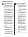
5
English
Do not insert your fi ngers
or other objects into the air
conditioner indoor or outdoor
unit, rotating parts may cause
injury.
Do not touch the outdoor unit during
lightning, it may cause electric shock.
Do not expose yourself directly to
cold air for a long period to avoid
excess cooling.
Do not sit or step on the unit,
you may fall down accidentally.
Remote control
Do not allow infants and small
children to play with the remote
control to prevent them from
accidentally swallowing the batteries.
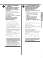
Power supply
Do not use a modifi ed
cord, joint cord,
extension cord or
unspecifi ed cord to
prevent overheating and
fi re.
To prevent overheating, fi re or electric
shock:
•
Do not share the same power outlet
with other equipment.
•
Do not operate with wet hands.
•
Do not over bend the power supply
cord.
•
Do not operate or stop the unit by
inserting or pulling out the power
plug.
If the supply cord is damaged, it must
be replaced by the manufacturer,
service agent or similarly qualifi ed
persons in order to avoid a hazard.
It is strongly recommended to be
installed with Earth Leakage Circuit
Breaker (ELCB) or Residual Current
Device (RCD) to prevent electric
shock or fi re.
To prevent overheating, fi re or electric
shock:
•
Insert the power plug properly.
•
Dust on the power plug should be
periodically wiped with a dry cloth.
Stop using the product if any
abnormality/failure occurs and
disconnect the power plug or turn off
the power switch and breaker.
(Risk of smoke/fi re/electric shock)
Examples of abnormality/failure
•
The ELCB trips frequently.
•
Burning smell is observed.
•
Abnormal noise or vibration of the
unit is observed.
•
Water leaks from the indoor unit.
•
Power cord or plug becomes
abnormally hot.
•
Fan speed cannot be controlled.
•
The unit stops running immediately
even if it is switched on for
operation.
•
The fan does not stop even if the
operation is stopped.
Contact your local dealer immediately
for maintenance/repair.
This equipment must be earthed to
prevent electrical shock or fi re.
Prevent electric shock by switching
off the power supply and unplug:
-Before cleaning or servicing,
-When extended non-use, or
-During abnormally strong lightning
activity.
Safety Precautions

6
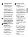
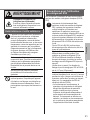
Safety Precautions
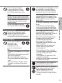
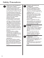
CAUTION
Indoor unit and outdoor unit
Do not wash the indoor unit with
water, benzine, thinner or scouring
powder to avoid damage or corrosion
at the unit.
Do not use for preservation of precise
equipment, food, animals, plants,
artwork or other objects. This may
cause quality deterioration, etc.
Do not use any combustible
equipment in front of the airfl ow outlet
to avoid fi re propagation.
Do not expose plants or pet directly
to airfl ow to avoid injury, etc.
Do not touch the sharp
aluminium fi n, sharp parts may
cause injury.
Do not switch ON the indoor unit
when waxing the fl oor. After waxing,
aerate the room properly before
operating the unit.
Do not install the unit in oily and
smoky areas to prevent damage to
the unit.
Do not dismantle the unit for cleaning
purpose to avoid injury.
Do not step onto an unstable bench
when cleaning the unit to avoid injury.
Do not place a vase or water
container on the unit. Water may
enter the unit and degrade the
insulation. This may cause an electric
shock.
Do not open window or door for
long time during operation, it may
lead to ineffi cient power usage and
uncomfortable temperature changes.
Prevent water leakage by ensuring
drainage pipe is:
- Connected properly,
- Kept clear of gutters and containers,
or
- Not immersed in water
After a long period of use or use with
any combustible equipment, aerate
the room regularly.
After a long period of use, make
sure the installation rack does not
deteriorate to prevent the unit from
falling down.
Remote control
Do not use rechargeable (Ni-Cd)
batteries. It may damage the remote
control.
To prevent malfunction or damage of
the remote control:
•
Remove the batteries if the unit
is not going to be used for a long
period of time.
•
New batteries of the same type must
be inserted following the polarity
stated.
Power supply
Do not disconnect the plug by pulling
the cord to prevent electric shock.

7
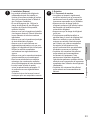
English
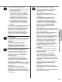
WARNING
This appliance is fi lled with
R32
(mild fl ammable refrigerant).
If the refrigerant is leaked and
exposed to an external ignition
source, there is a risk of fi re.
Indoor unit and outdoor unit
The appliance shall be installed, and/
or operated in a room with fl oor area
larger than Amin (m²) and keep away
from ignition sources, such as heat/
sparks/open fl ame or hazardous
areas such as gas appliances,
gas cooking, reticulated gas
supply systems or electric cooking
appliances, etc. (Refer to Table A of
Installation instructions table for Amin
(m²))
Be aware that refrigerant may
not contain an odour, highly
recommended to ensure suitable
fl ammable refrigerant gas detectors
are present, operating and able to
warn of a leak.
Keep any required ventilation
openings clear of obstruction.
Do not pierce or burn as the
appliance is pressurized. Do not
expose the appliance to heat, fl ame,
sparks, or other sources of ignition.
Else it may explode and cause injury
or death.
Precaution for using R32
refrigerant
The basic installation work procedures are
the same as conventional refrigerant (R410A,
R22) models.
Since the working pressure is
higher than that of refrigerant R22
models, some of the piping and
installation and service tools are
special. Especially, when replacing
a refrigerant R22 model with a
new refrigerant R32 model, always
replace the conventional piping and
fl are nuts with the R32 and R410A
piping and fl are nuts on the outdoor
unit side.
For R32 and R410A, the same fl are
nut on the outdoor unit side and pipe
can be used.
The mixing of different refrigerants
within a system is prohibited. Models
that use refrigerant R32 and R410A
have a different charging port thread
diameter to prevent erroneous
charging with refrigerant R22 and for
safety.
Therefore, check beforehand. [The
charging port thread diameter for R32
and R410A is 1/2 inch.]
Must always ensure that foreign
matter (oil, water, etc.) does not enter
the piping. Also, when storing the
piping, securely seal the opening by
pinching, taping, etc. (Handling of
R32 is similar to R410A.)
•
Operation, maintenance, repairing
and refrigerant recovery should be
carried out by trained and certifi ed
personnel in the use of fl ammable
refrigerants and as recommended
by the manufacturer. Any personnel
conducting an operation, servicing
or maintenance on a system or
associated parts of the equipment
should be trained and certifi ed.
Safety Precautions

8
•
Any part of refrigerating circuit
(evaporators, air coolers, AHU,
condensers or liquid receivers) or
piping should not be located in the
proximity of heat sources, open
fl ames, operating gas appliance or
an operating electric heater.
•
The user/owner or their authorised
representative shall regularly check
the alarms, mechanical ventilation
and detectors, at least once a
year, where as required by national
regulations, to ensure their correct
functioning.
•
A logbook shall be maintained. The
results of these checks shall be
recorded in the logbook.
•
In case of ventilations in occupied
spaces shall be checked to confi rm
no obstruction.
•
Before a new refrigerating system
is put into service, the person
responsible for placing the system
in operation should ensure that
trained and certifi ed operating
personnel are instructed on the
basis of the instruction manual
about the construction, supervision,
operation and maintenance of the
refrigerating system, as well as the
safety measures to be observed,
and the properties and handling of
the refrigerant used.
•
The general requirement of trained
and certifi ed personnel are indicated
as below:
a) Knowledge of legislation,
regulations and standards
relating to fl ammable
refrigerants; and,
b) Detailed knowledge of and
skills in handling fl ammable
refrigerants, personal protective
equipment, refrigerant leakage
prevention, handling of cylinders,
charging, leak detection,
recovery and disposal; and,
c) Able to understand and to apply
in practice the requirements
in the national legislation,
regulations and Standards; and,
d) Continuously undergo regular
and further training to maintain
this expertise.
e) Air-conditioner piping in the
occupied space shall be installed
in such a way to protect against
accidental damage in operation
and service.
f) Precautions shall be taken to
avoid excessive vibration or
pulsation to refrigerating piping.
g) Ensure protection devices,
refrigerating piping and fi ttings
are well protected against
adverse environmental effects
(such as the danger of water
collecting and freezing in relief
pipes or the accumulation of dirt
and debris).
h) Expansion and contraction of
long runs piping in refrigerating
systems shall be designed and
installed securely (mounted
and guarded) to minimize the
likelihood hydraulic shock
damaging the system.
i) Protect the refrigerating
system from accidental rupture
due to moving furniture or
reconstruction activities.
j) To ensure no leaking, fi eld-made
refrigerant joints indoors shall
be tightness tested. The test
method shall have a sensitivity
of 5 grams per year of refrigerant
or better under a pressure of at
least 0.25 times the maximum
allowable pressure (>1.04 MPa,
max 4.15 MPa). No leak shall be
detected.
Safety Precautions

9
English
1. Installation (Space)
•
Product with fl ammable refrigerants,
shall be installed according to
the minimum room area, Amin
(m²) mentioned in Table A of the
Installation Instructions.
•
In case of fi eld charge, the effect
on refrigerant charge caused by
the different pipe length has to be
quantifi ed, measured and labelled.
•
Must ensure the installation of pipe-
work shall be kept to a minimum.
Avoid use dented pipe and do not
allow acute bending.
•
Must ensure that pipe-work shall be
protected from physical damage.
•
Must comply with national gas
regulations, state municipal rules
and legislation. Notify relevant
authorities in accordance with all
applicable regulations.
•
Must ensure mechanical
connections be accessible for
maintenance purposes.
•
In cases that require mechanical
ventilation, ventilation openings shall
be kept clear of obstruction.
•
When disposal of the product, do
follow to the precautions in #12 and
comply with national regulations.
Always contact to local municipal
offi ces for proper handling.
2. Servicing
2-1. Service personnel
•
The system is inspected, regularly
supervised and maintained by
a trained and certifi ed service
personnel who is employed by the
person user or party responsible.
•
Ensure the actual refrigerant charge
is in accordance with the room
size within which the refrigerant
containing parts are installed.
•
Ensure refrigerant charge not to
leak.
•
Any qualifi ed person who is involved
with working on or breaking into
a refrigerant circuit should hold
a current valid certifi cate from an
industry-accredited assessment
authority, which authorizes their
competence to handle refrigerants
safely in accordance with an
industry recognised assessment
specifi cation.
•
Servicing shall only be performed
as recommended by the equipment
manufacturer. Maintenance and
repair requiring the assistance of
other skilled personnel shall be
carried out under the supervision of
the person competent in the use of
fl ammable refrigerants.
•
Servicing shall be performed only as
recommended by the manufacturer.
Safety Precautions

10
Safety Precautions
2-2. Work
•
Prior to beginning work on systems
containing fl ammable refrigerants,
safety checks are necessary to
ensure that the risk of ignition
is minimised.
For repair to the
refrigerating system, the precautions in
#2-2 to #2-8 must be followed before
conducting work on the system.
•
Work shall be undertaken under
a controlled procedure so as to
minimize the risk of a fl ammable gas
or vapour being present while the
work is being performed.
•
All maintenance staff and others
working in the local area shall be
instructed and supervised on the
nature of work being carried out.
•
Avoid working in confi ned spaces.
Always ensure away from source, at
least 2 meter of safety distance, or
zoning of free space area of at least
2 meter in radius.
•
Wear appropriate protective
equipment, including respiratory
protection, as conditions warrant.
•
Keep all sources of ignition and hot
metal surfaces away.
2-3. Checking for presence of
refrigerant
•
The area shall be checked with an
appropriate refrigerant detector prior
to and during work, to ensure the
technician is aware of potentially
fl ammable atmospheres.
•
Ensure that the leak detection
equipment being used is suitable for
use with fl ammable refrigerants, i.e.
non sparking, adequately sealed or
intrinsically safe.
•
In case of leakage/spillage
happened, immediately ventilate
area and stay upwind and away
from spill/release.
•
In case of leakage/spillage
happened, do notify persons down
wind of the leaking/spill, isolate
immediate hazard area and keep
unauthorised personnel out.
2-4. Presence of fi re extinguisher
•
If any hot work is to be conducted
on the refrigerating equipment or
any associated parts, appropriate
fi re extinguishing equipment shall be
available at hand.
•
Have a dry powder or CO
2
fi re
extinguisher adjacent to the
charging area.
2-5. No ignition sources
•
No person carrying out work in
relation to a refrigerating system
which involves exposing any pipe
work that contains or has contained
fl ammable refrigerant shall use any
sources of ignition in such a manner
that it may lead to the risk of fi re
or explosion. He/She must not be
smoking when carrying out such
work.
•
All possible ignition sources,
including cigarette smoking, should
be kept suffi ciently far away from
the site of installation, repairing,
removing and disposal, during which
fl ammable refrigerant can possibly
be released to the surrounding
space.
•
Prior to work taking place, the area
around the equipment is to be
surveyed to make sure that there
are no fl ammable hazards or ignition
risks.
•
“No Smoking” signs shall be
displayed.
2-6. Ventilated area
•
Ensure that the area is in the open
or that it is adequately ventilated
before breaking into the system or
conducting any hot work.
•
A degree of ventilation shall continue
during the period that the work is
carried out.
•
The ventilation should safely
disperse any released refrigerant
and preferably expel it externally
into the atmosphere.

11
English
2-7. Checks to the refrigerating
equipment
•
Where electrical components are
being changed, they shall be fi t
for the purpose and to the correct
specifi cation.
•
At all times the manufacturer’s
maintenance and service guidelines
shall be followed.
•
If in doubt consult the
manufacturer’s technical department
for assistance.
•
The following checks shall be
applied to installations using
fl ammable refrigerants.
-
The actual refrigerant charge
is in accordance with the room
size within which the refrigerant
containing parts are installed.
-
The ventilation machinery and
outlets are operating adequately
and are not obstructed.
-
If an indirect refrigerating circuit is
being used, the secondary circuit
shall be checked for the presence
of refrigerant.
-
Marking to the equipment
continues to be visible and legible.
Markings and signs that are
illegible shall be corrected.
-
Refrigerating pipe or components
are installed in a position where
they are unlikely to be exposed to
any substance which may corrode
refrigerant containing components,
unless the components are
constructed of materials which
are inherently resistant to being
corroded or are properly protected
against being so corroded.
2-8. Checks to electrical devices
•
Repair and maintenance to electrical
components shall include initial
safety checks and component
inspection procedures.
•
Initial safety checks shall include but
not limit to:-
-
That capacitors are discharged:
this shall be done in a safe
manner to avoid possibility of
sparking.
-
That there no live electrical
components and wiring are
exposed while charging,
recovering or purging the system.
-
That there is continuity of earth
bonding.
•
At all times the manufacturer’s
maintenance and service guidelines
shall be followed.
•
If in doubt consult the
manufacturer’s technical department
for assistance.
•
If a fault exists that could
compromise safety, then no
electrical supply shall be connected
to the circuit until it is satisfactorily
dealt with.
•
If the fault cannot be corrected
immediately but it is necessary to
continue operation, an adequate
temporary solution shall be used.
•
The owner of the equipment must be
informed or reported so all parties
are advised thereinafter.
Safety Precautions

12
Safety Precautions
3. Repairs to sealed components
•
During repairs to sealed
components, all electrical supplies
shall be disconnected from the
equipment being worked upon prior
to any removal of sealed covers, etc.
•
If it is absolutely necessary to have
an electrical supply to equipment
during servicing, then a permanently
operating form of leak detection
shall be located at the most critical
point to warn of a potentially
hazardous situation.
•
Particular attention shall be paid
to the following to ensure that by
working on electrical components,
the casing is not altered in such a
way that the level of protection is
affected.This shall include damage
to cables, excessive number of
connections, terminals not made
to original specifi cation, damage to
seals, incorrect fi tting of glands, etc.
•
Ensure that apparatus is mounted
securely.
•
Ensure that seals or sealing
materials have not degraded
such that they no longer serve the
purpose of preventing the ingress of
fl ammable atmospheres.
•
Replacement parts shall be in
accordance with the manufacturer’s
specifi cations.
NOTE: The use of silicon sealant
may inhibit the effectiveness of some
types of leak detection equipment.
Intrinsically safe components do not
have to be isolated prior to working
on them.
4. Repair to intrinsically safe
components
•
Do not apply any permanent
inductive or capacitance loads to
the circuit without ensuring that
this will not exceed the permissible
voltage and current permitted for the
equipment in use.
•
Intrinsically safe components are
the only types that can be worked
on while live in the presence of a
fl ammable atmosphere.
•
The test apparatus shall be at the
correct rating.
•
Replace components only with
parts specifi ed by the manufacturer.
Unspecifi ed parts by manufacturer
may result ignition of refrigerant in
the atmosphere from a leak.
5. Cabling
•
Check that cabling will not be
subject to wear, corrosion, excessive
pressure, vibration, sharp edges or
any other adverse environmental
effects.
•
The check shall also take into
account the effects of aging or
continual vibration from sources
such as compressors or fans.
6. Detection of fl ammable
refrigerants
•
Under no circumstances shall
potential sources of ignition be used
in the searching or detection of
refrigerant leaks.
•
A halide torch (or any other detector
using a naked fl ame) shall not be
used.

13
English
7. The following leak detection
methods are deemed
acceptable for all refrigerant
systems
•
No leaks shall be detected when
using detection equipment with
a sensitivity of 5 grams per year
of refrigerant or better under a
pressure of at least 0.25 times the
maximum allowable pressure
(>1.04 MPa, max 4.15 MPa), for
example, a universal sniffer.
•
Electronic leak detectors may
be used to detect fl ammable
refrigerants, but the sensitivity may
not be adequate, or may need re-
calibration.
(Detection equipment shall be
calibrated in a refrigerant-free area.)
•
Ensure that the detector is not a
potential source of ignition and is
suitable for the refrigerant used.
•
Leak detection equipment shall be
set at a percentage of the LFL of the
refrigerant and shall be calibrated
to the refrigerant employed and the
appropriate percentage of gas (25 %
maximum) is confi rmed.
•
Leak detection fl uids are also
suitable for use with most
refrigerants, for example, bubble
method and fl uorescent method
agents. The use of detergents
containing chlorine shall be avoided
as the chlorine may react with the
refrigerant and corrode the copper
pipe-work.
•
If a leak is suspected, all naked
fl ames shall be removed/
extinguished.
•
If a leakage of refrigerant is found
which requires brazing, all of the
refrigerant shall be recovered from
the system, or isolated (by means
of shut off valves) in a part of the
system remote from the leak. The
precautions in #8 must be followed
to remove the refrigerant.
8. Removal and evacuation
•
When breaking into the refrigerant
circuit to make repairs – or for
any other purpose – conventional
procedures shall be used. However,
it is important that best practice
is followed since fl ammability is
a consideration. The following
procedure shall be adhered to:
remove refrigerant -> purge the
circuit with inert gas -> evacuate
-> purge with inert gas -> open the
circuit by cutting or brazing.
•
The refrigerant charge shall be
recovered into the correct recovery
cylinders.
•
The system shall be purged with
OFN to render the appliance safe.
•
This process may need to be
repeated several times.
•
Compressed air or oxygen shall not
be used for this task.
•
Purging shall be achieved by
breaking the vacuum in the system
with OFN and continuing to fi ll until
the working pressure is achieved,
then venting to atmosphere, and
fi nally pulling down to a vacuum.
•
This process shall be repeated until
no refrigerant is within the system.
•
When the fi nal OFN charge is used,
the system shall be vented down
to atmospheric pressure to enable
work to take place.
•
This operation is absolutely vital if
brazing operations on the pipe work
are to take place.
•
Ensure that the outlet for the
vacuum pump is not close to any
potential ignition sources and there
is ventilation available.
OFN = oxygen free nitrogen,
type of inert gas.
Safety Precautions

14
Safety Precautions
9. Charging procedures
•
In addition to conventional
charging procedures, the following
requirements shall be followed.
-
Ensure that contamination of
different refrigerants does not
occur when using charging
equipment.
-
Hoses or lines shall be as short as
possible to minimize the amount of
refrigerant contained in them.
-
Cylinders shall be kept in an
appropriate position according to
the instructions.
-
Ensure that the refrigerating
system is earthed prior to charging
the system with refrigerant.
-
Label the system when charging is
complete (if not already).
-
Extreme care shall be taken not to
over fi ll the refrigerating system.
•
Prior to recharging the system it
shall be pressure tested with OFN
(refer to #7).
•
The system shall be leak tested on
completion of charging but prior to
commissioning.
•
A follow up leak test shall be carried
out prior to leaving the site.
•
Electrostatic charge may
accumulate and create a hazardous
condition when charging and
discharging the refrigerant. To
avoid fi re or explosion, dissipate
static electricity during transfer by
grounding and bonding containers
and equipment before charging/
discharging.
10. Decommissioning
•
Before carrying out this procedure,
it is essential that the technician
is completely familiar with the
equipment and all its details.
•
It is recommended good practice
that all refrigerants are recovered
safely.
•
Prior to the task being carried
out, an oil and refrigerant sample
shall be taken in case analysis is
required prior to re-use of recovered
refrigerant.
•
It is essential that electrical power
is available before the task is
commenced.
a) Become familiar with the
equipment and its operation.
b) Isolate system electrically.
c) Before attempting the procedure
ensure that:
•
mechanical handling equipment is
available, if required, for handling
refrigerant cylinders;
•
all personal protective equipment
is available and being used
correctly;
•
the recovery process is
supervised at all times by a
competent person;
•
recovery equipment and cylinders
conform to the appropriate
standards.
d) Pump down refrigerant system, if
possible.
e) If a vacuum is not possible, make
a manifold so that refrigerant can
be removed from various parts of
the system.
f) Make sure that cylinder is
situated on the scales before
recovery takes place.
g) Start the recovery machine and
operate in accordance with
instructions.
h) Do not over fi ll cylinders. (No
more than 80 % volume liquid
charge).

15
English
i) Do not exceed the maximum
working pressure of the cylinder,
even temporarily.
j) When the cylinders have been
fi lled correctly and the process
completed, make sure that the
cylinders and the equipment
are removed from site promptly
and all isolation valves on the
equipment are closed off.
k) Recovered refrigerant shall not be
charged into another refrigerating
system unless it has been
cleaned and checked.
•
Electrostatic charge may accumulate
and create a hazardous condition
when charging or discharging the
refrigerant. To avoid fi re or explosion,
dissipate static electricity during
transfer by grounding and bonding
containers and equipment before
charging/discharging.
11. Labelling
•
Equipment shall be labelled stating
that it has been de-commissioned
and emptied of refrigerant.
•
The label shall be dated and signed.
•
Ensure that there are labels on the
equipment stating the equipment
contains fl ammable refrigerant.
12. Recovery
•
When removing refrigerant from
a system, either for servicing
or decommissioning, it is
recommended good practice that all
refrigerants are removed safely.
•
When transferring refrigerant
into cylinders, ensure that only
appropriate refrigerant recovery
cylinders are employed.
•
Ensure that the correct number of
cylinders for holding the total system
charge are available.
•
All cylinders to be used are
designated for the recovered
refrigerant and labelled for that
refrigerant (i.e. special cylinders for
the recovery of refrigerant).
•
Cylinders shall be complete
with pressure relief valve and
associated shut-off valves in good
working order.
•
Recovery cylinders are evacuated
and, if possible, cooled before
recovery occurs.
•
The recovery equipment shall
be in good working order with a
set of instructions concerning the
equipment that is at hand and
shall be suitable for the recovery of
fl ammable refrigerants.
•
In addition, a set of calibrated
weighing scales shall be available
and in good working order.
•
Hoses shall be complete with leak-
free disconnect couplings and in
good condition.
•
Before using the recovery machine,
check that it is in satisfactory
working order, has been properly
maintained and that any associated
electrical components are sealed
to prevent ignition in the event
of a refrigerant release. Consult
manufacturer if in doubt.
•
The recovered refrigerant shall be
returned to the refrigerant supplier
in the correct recovery cylinder, and
the relevant Waste Transfer Note
arranged.
•
Do not mix refrigerants in recovery
units and especially not in cylinders.
•
If compressors or compressor oils
are to be removed, ensure that
they have been evacuated to an
acceptable level to make certain
that fl ammable refrigerant does not
remain within the lubricant.
•
The evacuation process shall be
carried out prior to returning the
compressor to the suppliers.
•
Only electric heating to the
compressor body shall be
employed to accelerate this
process.
•
When oil is drained from a system,
it shall be carried out safely.
Safety Precautions

16
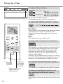
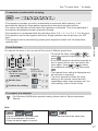
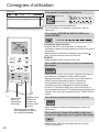
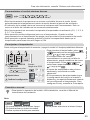
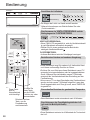
How to Use
Indicators
To adjust airfl ow direction To adjust airfl ow direction
Upper direction
Lateral direction
• Do not adjust the fl ap by hand.
* For details operation, refer “To Learn More....”
FAN SPEED:
•
When FAN AUTO is selected, the fan speed is adjusted
automatically according to the operation mode.
•
Select the lowest fan speed to have a low noise
operation.
QUIET:
•
This operation reduces airfl ow noise.
To adjust FAN SPEED and QUIET condition
Not used
in normal
operation.
Press to restore the
remote control to
default setting.
Press to turn
the Wireless
LAN feature
ON or OFF.
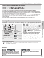
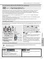
To enjoy fresher and cleaner environment
• This operation provides cleaner air, moisturises your
skin and hair, and deodorises odours in the room.
• Press nanoe™X to activate this operation, either
when the unit is ON or OFF. During nanoe™X
individual operation, the fan speed will follow the
remote control setting.
• If nanoe™X is activated before the unit is turned off,
the nanoe™X operation will resume when the unit is
turned on. This includes when TIMER ON is set.
•
This operation reduces air dryness during COOL mode
only.
To improve humidity and moisture level
(Not applicable for Multi split system)
•
This operation is automatically stop after 20 minutes.
To reach the desired temperature quickly

17
English
See "To Learn More..." for details.
• To cancel the timer, press
or to
select the respective setting
or , then
press
.
• If the timer has been cancelled manually or
due to power failure, you can restore the
timer again. Press
or to select
the respective setting
or , then press
.
• The nearest timer setting is displayed and
will activate in sequence.
• The timer operation follows the clock
setting on the remote control and will
repeat daily when timer has been set. For
clock setting, refer to Quick Guide.
You can set the timer to turn on and off the unit at 2 different preset time.
3
1 2
Select TIMER ON
or TIMER OFF.
Example:
OFF at 22:00
• Each time pressed:
(exit setting)
Set the time.
Confi rm the setting.
1
2
3
Note
, ,
,
• Can be selected at the same time.
• Can be activated in all modes.
• Press the button again to cancel.
• Cannot be selected at the same time.
• This operation provides you with a comfortable environment while sleeping. It will
automatically adjust the sleep pattern temperature during the activation period.
• The indoor unit indicator will dim when this operation is activated. This is not applicable if
the indicator brightness has been manually dimmed.
• This operation is incorporated with the activation timer (0.5, 1, 2, 3, 4, 5, 6, 7, 8 or 9 hours).
• This operation can be set together with timer. Sleep operation has the priority over OFF
timer.
• This operation can be cancelled by pressing the respective button until the sleep timer
reaches 0.0h.
• For Wireless LAN Module operation setup, please refer to Setup Instructions
Manual.
How to Use
To maximise comfort while sleeping
To set the timer
To connect to a network

18
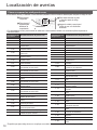
Energy saving temperature setting
You may save energy when operating the unit within the recommended temperature range.
HEAT : 20.0 °C ~ 24.0 °C / 68 °F ~ 75 °F.
COOL: 26.0 °C ~ 28.0 °C / 79 °F ~ 82 °F.
Air fl ow direction
In COOL/DRY mode:
The horizontal fl ap swings up/down automatically.
Once the temperature is achieved, the horizontal fl ap is fi xed at upper position.
In HEAT mode:
The horizontal fl ap fi xed at the predetermined position.
The vertical fl ap swings left/right when the temperature rises.
In COOL/DRY/HEAT mode:
The horizontal fl ap swings up/down automatically.
In MILD DRY (Not applicable for Multi split system):
When vertical airfl ow direction is set to AUTO, it stops at lower position to avoid cold air
contact. However, you can adjust the fl ap direction manually.
Auto restart control
When power is resumed after a power failure, the operation will restart automatically with the
last operation mode and airfl ow direction.
• This control is not applicable when TIMER is set.
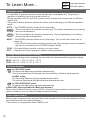
To Learn More...
Single Single split system
Multi
Multi split system
Operation mode
• It is possible to operate the indoor units individually or simultaneously. The priority of
operation is placed on the fi rst unit that turned on.
• During operation, HEAT and COOL modes cannot activate at the same time for different
indoor units.
• The power indicator blinks to indicate the indoor unit is standing by for different operation
mode.
AUTO : The POWER indicator blinks at the initial stage.
Single
• The unit will select an operation mode every 10 minutes depending on the setting
and room temperature.
Multi
• The unit will select an operation mode every 3 hours depending on the setting,
room and outdoor temperature.
HEAT : The POWER indicator blinks at the initial stage. The unit will take some time to
warm up.
• If the HEAT mode system has been locked, and other operation mode is selected,
the indoor unit stops and the POWER indicator blinks.
COOL : Provides effi cient comfort cooling to suit your needs.
DRY : Operates at low fan speed for a gentle cooling operation.

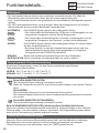
19
English
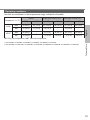
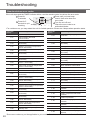
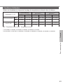
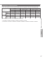
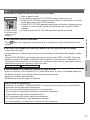
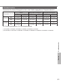
Operating conditions
Use this air conditioner in the temperature range indicated in the table.
Temperature
°C (°F)
Indoor
Single split outdoor unit
*
1
Multi split outdoor unit *
2
DBT WBT DBT WBT DBT WBT
COOL
Max. 32 (89.6) 23 (73.4) 43 (109.4) 26 (78.8) 46 (114.8) 26 (78.8)
Min. 16 (60.8) 11 (51.8) -10 (14.0) - -10 (14.0) -
HEAT
Max. 30 (86.0) - 24 (75.2) 18 (64.4) 24 (75.2) 18 (64.4)
Min. 16 (60.8) - -15 (5.0) -16 (3.2) -15 (5.0) -16 (3.2)
DBT: Dry bulb temperature, WBT: Wet bulb temperature
*
1
CU-Z20XKE, CU-Z25XKE, CU-Z35XKE, CU-Z42XKE, CU-Z50XKE, CU-Z71XKE
*
2
CU-2Z35TBE, CU-2Z41TBE, CU-2Z50TBE, CU-3Z52TBE, CU-3Z68TBE, CU-4Z68TBE, CU-4Z80TBE, CU-5Z90TBE
To Learn More...

20
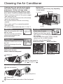
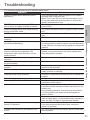
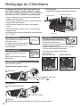
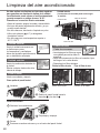
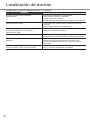
Cleaning the Air Conditioner
Cleaning has to be carried out at regular
intervals to ensure the unit is at optimal
performance. A dirty unit may cause
malfunction and you may retrieve “H 99”
error code. Consult an authorised dealer.
• Before cleaning, switch off the power supply
and unplug the unit.
• Do not touch the aluminium fi n as the sharp
parts may cause injury.
• Do not use benzine, thinner or scouring
powder.
• Use soap (
pH 7) or neutral household
detergent only.
• Do not use water hotter than 40 °C / 104 °F.
Indoor unit
( Structure of the unit may vary depending
on the model)
Aluminium fi n
Front panel
Air fi lters
Indoor unit
Wipe the unit gently with a soft
and dry cloth.
The coils and fans should be
cleaned periodically by an
authorised dealer.
Outdoor unit
Clean the debris that surround
the unit.
Clear any blockage from the
drain pipe.
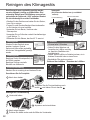
Front panel
Wash gently and dry.
How to remove front panel
1
Raise up.
B
A
Close it securely
1
Hold horizontally.
3
Close down.
4
Press both ends and center of the front panel.
Air fi lters
Once every 2 weeks
• Wash/rinse the fi lters gently
with water to avoid damaging
the surface.
• Dry the fi lters thoroughly under a shade,
away from fi re or direct sunlight.
• Replace any damaged fi lters.
Remove air fi lter Attach air fi lter
Remove from the unit Insert into the unit
2
Slide the front panel to
right
A
and pull out
B
.
2
Match and push in.
La page est en cours de chargement...
La page est en cours de chargement...
La page est en cours de chargement...
La page est en cours de chargement...
La page est en cours de chargement...
La page est en cours de chargement...
La page est en cours de chargement...
La page est en cours de chargement...
La page est en cours de chargement...
La page est en cours de chargement...
La page est en cours de chargement...
La page est en cours de chargement...
La page est en cours de chargement...
La page est en cours de chargement...
La page est en cours de chargement...
La page est en cours de chargement...
La page est en cours de chargement...
La page est en cours de chargement...
La page est en cours de chargement...
La page est en cours de chargement...
La page est en cours de chargement...
La page est en cours de chargement...
La page est en cours de chargement...
La page est en cours de chargement...
La page est en cours de chargement...
La page est en cours de chargement...
La page est en cours de chargement...
La page est en cours de chargement...
La page est en cours de chargement...
La page est en cours de chargement...
La page est en cours de chargement...
La page est en cours de chargement...
La page est en cours de chargement...
La page est en cours de chargement...
La page est en cours de chargement...
La page est en cours de chargement...
La page est en cours de chargement...
La page est en cours de chargement...
La page est en cours de chargement...
La page est en cours de chargement...
La page est en cours de chargement...
La page est en cours de chargement...
La page est en cours de chargement...
La page est en cours de chargement...
La page est en cours de chargement...
La page est en cours de chargement...
La page est en cours de chargement...
La page est en cours de chargement...
La page est en cours de chargement...
La page est en cours de chargement...
La page est en cours de chargement...
La page est en cours de chargement...
La page est en cours de chargement...
La page est en cours de chargement...
La page est en cours de chargement...
La page est en cours de chargement...
La page est en cours de chargement...
La page est en cours de chargement...
La page est en cours de chargement...
La page est en cours de chargement...
La page est en cours de chargement...
La page est en cours de chargement...
La page est en cours de chargement...
La page est en cours de chargement...
La page est en cours de chargement...
La page est en cours de chargement...
La page est en cours de chargement...
La page est en cours de chargement...
La page est en cours de chargement...
La page est en cours de chargement...
La page est en cours de chargement...
La page est en cours de chargement...
La page est en cours de chargement...
La page est en cours de chargement...
La page est en cours de chargement...
La page est en cours de chargement...
La page est en cours de chargement...
La page est en cours de chargement...
La page est en cours de chargement...
La page est en cours de chargement...
-
 1
1
-
 2
2
-
 3
3
-
 4
4
-
 5
5
-
 6
6
-
 7
7
-
 8
8
-
 9
9
-
 10
10
-
 11
11
-
 12
12
-
 13
13
-
 14
14
-
 15
15
-
 16
16
-
 17
17
-
 18
18
-
 19
19
-
 20
20
-
 21
21
-
 22
22
-
 23
23
-
 24
24
-
 25
25
-
 26
26
-
 27
27
-
 28
28
-
 29
29
-
 30
30
-
 31
31
-
 32
32
-
 33
33
-
 34
34
-
 35
35
-
 36
36
-
 37
37
-
 38
38
-
 39
39
-
 40
40
-
 41
41
-
 42
42
-
 43
43
-
 44
44
-
 45
45
-
 46
46
-
 47
47
-
 48
48
-
 49
49
-
 50
50
-
 51
51
-
 52
52
-
 53
53
-
 54
54
-
 55
55
-
 56
56
-
 57
57
-
 58
58
-
 59
59
-
 60
60
-
 61
61
-
 62
62
-
 63
63
-
 64
64
-
 65
65
-
 66
66
-
 67
67
-
 68
68
-
 69
69
-
 70
70
-
 71
71
-
 72
72
-
 73
73
-
 74
74
-
 75
75
-
 76
76
-
 77
77
-
 78
78
-
 79
79
-
 80
80
-
 81
81
-
 82
82
-
 83
83
-
 84
84
-
 85
85
-
 86
86
-
 87
87
-
 88
88
-
 89
89
-
 90
90
-
 91
91
-
 92
92
-
 93
93
-
 94
94
-
 95
95
-
 96
96
-
 97
97
-
 98
98
-
 99
99
-
 100
100


Panasonic CSMZ16XKE Mode d'emploi
- Catégorie
- Climatiseurs split-system
- Taper
- Mode d'emploi
dans d''autres langues
Documents connexes
-
Panasonic CU2TZ50TBE Mode d'emploi
-
Panasonic CUUZ50WKE Le manuel du propriétaire
-
-
Panasonic CSXZ35VKEW Le manuel du propriétaire
-
Panasonic FZ 5 Le manuel du propriétaire
-
Panasonic WHADC0309J3E5 Mode d'emploi
-
-
-
-
Autres documents
-
Taurus Alpatec AC 7001 C - COLD DIGITAL Le manuel du propriétaire
-
-
-
Midea Mobile 35C Le manuel du propriétaire
-
Century RADS-121R Installation, Operation & Maintenance Manual
-
Danby DAC100B6IWDB-6 Le manuel du propriétaire
-
Danby DPA100B9IWDB-6 Le manuel du propriétaire
-
QLIMA D620 Manuel utilisateur
-
Mitsubishi Electric PXZ-4F75VG Split-Type Air-Conditioner Manuel utilisateur
-
Hitachi RAC-18WPE Manuel utilisateur