Dri-Eaz F410 LGR 2800i Portable Dehumidifier Manuel utilisateur
- Catégorie
- Déshumidificateurs
- Taper
- Manuel utilisateur

110489R (07-01674) F410, F411 1 Legend Brands, Inc.
Owner’s Manual
LGR 2800i Portable Dehumidifier (F410)
LGR 3500i Portable Dehumidifier (F411)
Legend Brands, Inc.
15180 Josh Wilson Road, Burlington, WA 98233
Phone: 800-932-3030 Fax: 360-757-7950 LegendBrandsRestoration.com
The Dri-Eaz
®
LGR i-Series dehumidifiers reduce humidity in enclosed structural environments by
removing water vapor from the air. The i-Series product line is engineered to be rugged, durable and
highly portable, making them ideally suited for water damage restoration, structural drying,
construction, and other applications requiring temporary, high-performance dehumidification.
Patents: LBpatents.com
READ AND UNDERSTAND BEFORE OPERATING
SAFETY INSTRUCTIONS
WARNING! Do not alter or modify your unit in any
way. Use only replacement parts authorized by
Dri-Eaz Products, Inc. Modifications or use of
unapproved parts could create a hazard and will
void your warranty. Contact your authorized
distributor for assistance.
WARNING! Electric shock hazard, rotating fan, hot
surface hazards. Unplug unit before opening cover
for cleaning or servicing. Unit must be grounded.
• Inspect the power cord before use. If cord is
damaged, do not use. Always grasp the plug (not
the cord) to unplug.
• Insert three-prong plug on power cord into a
matching electrically grounded outlet. Do not use
adapter. Never cut off third prong. Do not use an
extension cord.
• The unit must be operated on a 115V/60Hz circuit
protected by a Ground Fault Circuit Interrupter
(GFCI) device.
• Keep motor and wiring dry.
• Do not attempt to repair the unit. For Authorized
Service Centers, contact Dri-Eaz.
NOTICE: Do not use in environments where
corrosive chemicals are present, such as chlorine.
BEFORE YOU BEGIN
Warranty registration
Visit warranty.LegendBrandsRestoration.com to register
your purchase. Registration allows us to better assist
you with using, maintaining or servicing your equipment
and to contact you in case we have important safety
information concerning your Dri-Eaz product. If you
determine service is required, have your equipment
model, serial number and original proof of purchase
available and call your distributor for assistance with
obtaining a return material authorization (RMA).
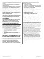
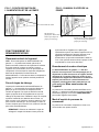
WARNING
CORRECT PLUG REMOVAL
Grasp IEC plug and pull straight out
IMPORTANT: Damage to IEC receptacle or
dehumidifier resulting from improper removal of
the power cord is not covered by warranty. The
IEC power cord is a wear item and is not covered
by warranty.

110489R (07-01674) F410, F411 2 Legend Brands, Inc.
INTRODUCTION
How LGR dehumidifiers work
Dri-Eaz LGR (low-grain refrigerant) dehumidifiers
operate by pulling moist air in across a very cold
evaporator core. The moisture in the air condenses on
the coil. In certain conditions, the machine operates in
defrost mode, warming any frost that has accumulated
on the evaporator coil back into water. The water
collects in a tray and is pumped out through a hose.
Onboard sensors continually monitor environmental
conditions and system operations of the dehumidifier,
including temperature and relative humidity, which can
be viewed on the display panel.
LGR dehumidifiers have better heat exchange and
defrost abilities than regular refrigerant dehumidifiers,
and are able to continue removing moisture in drier
environments.
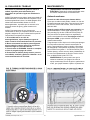
POSITIONING A DEHUMIDIFIER
For best results, operate your dehumidifiers in an
enclosed area, as this creates a drying chamber. Close
all doors and windows that open to the outside to
maximize the unit’s water removal efficiency. Also, keep
traffic though the drying chamber to a minimum. Place
your dehumidifier against a wall, away from obstructions,
and keep it away from anything that could block airflow
into and out of the unit.
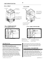
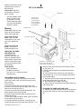
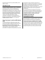
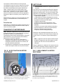
Rugged rotomolded
housing resists dents
and scratches and is
easy to maintain.
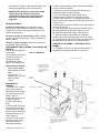
FIG. B: REAR
Integrated handle.
Lower back panel. Remove
this panel to access the
pump for servicing.
Drain hose pocket.
Control panel.
Molded pocket
for cord storage.
Humid air inlet
(both sides).
Process (dehumidified)
air outlet. May be used
with standard 12" rigid
or layflat ducting.
FIG. A: FRONT
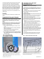
FIG. C: POWER AND PUMP
ATTACHMENT POINTS
Power cord socket.
Lower back panel. Remove the
five retaining screws to remove
pump for cleaning.
FIG. D: PUMP ACCESS PANEL
Bottom of back
polyethylene housing.
Remove two bolts to
remove pump for cleaning.
PARTS IDENTIFICATION

110489R (07-01674) F410, F411 3 Legend Brands, Inc.
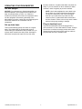
OPERATING YOUR DEHUMIDIFIER
Set unit upright
NOTICE: If you transport an i-Series dehumidifier in a
horizontal position, set it upright and let it stand for at
least 30 minutes before you turn it on. When the
machine is horizontal, the oil from the compressor flows
into the refrigerant coils reducing the ability of the
dehumidifier to function. Letting the unit stand upright for
30 minutes allows the oil to flow back into the
compressor.
Set up drain hose
This unit automatically pumps out water on a regular
basis. This dehumidifier is equipped with a quick-
connect fitting for attachment to the provided 40 ft. (12
m) drain hose located in the side pocket. Unwrap the
entire hose and place the open end in a sink, drain,
bucket or outdoors – anywhere that water can drain out
safely. If you use a bucket or other container for water
collection, check it regularly to prevent overflows.
NOTE: Uncoil and straighten the entire drain hose.
Do not leave any of part of the hose coiled on the
unit and do not place the end of the hose higher
than 20 ft. (6 m) above the top of the unit. Also
check for kinks, or obstructions that would restrict
the flow of water. Failure to do so may cause a water
backup in the pump resulting in leakage.
Plug in electrical cord
The i-Series dehumidifier should be plugged into a
GFCI-protected 115 volt outlet rated for at least 15
amps.
Remove the cord from its storage pocket and uncoil it.
Always plug the cord firmly into the unit first, and then
plug the other end into a suitable outlet.

110489R (07-01674) F410, F411 4 Legend Brands, Inc.
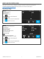
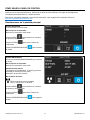
HOW TO USE THE CONTROL PANEL
The i-Series Controller provides comprehensive dehumidifier controls and detailed real-time data about the drying
environment as well as job hours, self-diagnosis messages, maintenance reminders and operating status.
For detailed information and additional instructions, please visit the i-Series Controller page at
Controller.LegendBrandsRestoration.com
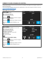
Home Screen Views
Unit OFF
Unit must be plugged in.
Top display bar:
Job hours, current time
Press MENU to access settings and
configuration controls
Press PURGE to pump out condensate tank
Press ON/OFF to turn unit on.
Unit ON
Press ON/OFF key to switch unit on.
Top display bar:
Job hours, current time
Information display:
Inlet/Outlet temp, %RH and GPP
Current GPP removal
Bottom menu bar:
Quick-Reference Inlet GPP.
1: < 60 GPP; 2: 60–90 GPP; 3: > 90 GPP
Press MENU to access settings and
configuration controls
Press PURGE to pump out condensate tank
Press ON/OFF to turn unit off.

110489R (07-01674) F410, F411 5 Legend Brands, Inc.
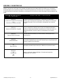
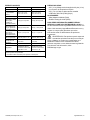
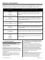
ERRORS AND WARNINGS
If the control system detects a problem, it will display an "Alert" symbol in the upper right corner of the screen. Press
ON/OFF to view the message and OK to clear the message. NOTE: In the case of an error, the unit will not operate until
the problem is resolved. Refer to the explanations and solutions shown below. If these solutions do not fix the problem,
contact your local authorized service center for further assistance.
CONTROL PANEL
MESSAGE
EXPLANATION AND SOLUTION
ER4 Error
Defrost Thermistor Connect
—or—
ER4 Error
Outlet Thermistor Connect
Temp sensor is open, missing, or shorted. Check that temp sensors are
installed correctly on control panel. If error persists, contact service.
ER5 Error
Inlet RH1 Temp/RH Sensor
Inlet Temp/RH sensor is open, missing, or shorted. Check that inlet
temp/RH sensor is installed correctly on control panel and inlet shroud. If
error persists, contact service.
ER5 Error
Inlet RH1 Temp/RH Sensor
Inlet Temp/RH sensor is open, missing, or shorted. Check that inlet
temp/RH sensor is installed correctly on control panel and inlet shroud. If
error persists, contact service.
ER6 Error
Current Sensor Failure
Current sensor failure. If error persists, contact service.
ER9 Error
Pump Blocked
Check for obstructions in drain hose. Check the pump.
W1
Low BATTERY
Replace coin cell battery (3V, CR2032) on control panel.
W2
BLE Error
W3
Flash Reset
W4
WDT Reset
Cycle power to dehumidifier. If warning persists, contact service.
AT THE END OF THE JOB
To reduce the possibility of drips when moving the
unit, follow these additional steps to ensure that all
water is removed from the unit.
NOTICE: The unit will complete the defrost cycle even if
the unit is turned off but still plugged in. If the unit is
unplugged during the defrost cycle, excessive water may
accumulate in the unit and may drip out when you move
the unit.
NOTICE: To ensure the condensate tank empties
completely while purging, make sure the unit is placed
upright on a horizontal surface.
1. Do not turn unit off or move it until it has returned
to normal operating mode.
2. Gently rock the machine to ensure any water
remaining on interior surfaces falls into the sump
area.
3. Press the PURGE key. When the purge cycle is
complete, turn the unit off.
4. Disconnect the external drain hose, drain it
carefully, coil it and secure it in the pocket or the
strap provided with your unit.
MAINTENANCE
WARNING! ELECTRIC SHOCK HAZARD. Unplug the
dehumidifier before performing any maintenance.
Before each use
Inspect the electrical cord for damage. Look for
fraying, cuts, etc. Do not use the unit if you find any

110489R (07-01674) F410, F411 6 Legend Brands, Inc.
damage. Call Dri-Eaz for the
nearest Service Center at
800-932-3030.
Inspect filter. Replace if
accumulation of dust and
debris is visible.
NOTICE: Replace used
filters only with a new
Dri-Eaz filter
#121708
(F584). Other filter types
do not provide adequate
filtration or airflow.
Monthly
Check coils. Dirty coils can
cause the unit to overheat.
Clean when visibly dirty.
Check heat exchange
block. Clean out with
compressed air only. Take
care not to damage the
block.
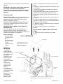
Inspect and clean the
pump. To remove the
condensate pump unit:
SERVICING THE PUMP
AND DRAIN PAN
To maintain proper
operation, the pump and
drain pan assembly should
be periodically removed and
cleaned. Follow these steps
to clean the pump and drain
pan assembly:
Tools Needed
Philips screwdriver
Flat blade screwdriver
⅜ in. and
15
∕
16
in. sockets and driver
Cleaning cloths
DISASSEMBLY AND CLEANING
1. Unplug unit, then remove the power cord from the
socket at the base of the unit. Remove pump hose at
quick-connect.
2. Remove filter.
3. Remove the two bolts from the upper front cover.
4. Remove one bolt each from the upper back corner of
side covers A and B (see Fig. A)
5. Remove four bolts from the lower back panel. The
back/top panel may now be removed.
6. Remove lower back metal panel (unscrew the five
attachment screws).
7. Place a firm support under the base of the unit so that
the left wheel may be removed.
8. Using the flat blade screwdriver, carefully pry the
center hub cap loose from the left wheel. Use the
15
∕
16
in.
socket to remove the retaining nut and slide the wheel
off. See Fig. E, #1.
9. Remove the two electric box retaining screws (see
Fig. E, #2.).
10. Tilt the bottom of the electric box to the right and
slide outward (Fig. F). It is not necessary to disconnect
any electrical cables.
11. Remove drain hose from pump assembly and slide
pump and tray assembly out of the unit.
12. Lift pump body out of plastic catch tray.
13. Wipe or rinse off all surfaces of the plastic catch tray
with a damp cloth.
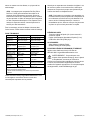
CLEANING THE PUMP AND PUMP TRAY
14. Remove the pump assembly from the pump tray and
set pump aside. Wipe or rinse out pump tray and wipe
dry.
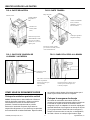
Rear cover
Side cover A
Side cover B
4-PRO filter
FIG. G: CLEANING
Pump hose – thread up through
hole in bottom of rear hose
pocket before reinstalling cover.
Condenser coil
Evaporator (cold) coil
Air-to-air heat
exchange block.
Arrows printed on
the block indicate
correct orientation
for installation.

110489R (07-01674) F410, F411 7 Legend Brands, Inc.
15. Remove pumpout hose from the check valve outlet.
16. Unscrew check valve. Using needle nose pliers,
carefully remove bottom of check valve assembly by
inserting one side of pliers approximately ⅛ in. into hole,
grasp and pull out carefully. A small ball bearing should
fall out so be careful not to lose it. Inspect assembly for
debris in assembly and clean accordingly. Reinstall the
ball bearing and reinstall the check valve assembly.
Reassemble in reverse order. The dehumidifier is now
ready for use.
Annually
Have the pump system inspected by a qualified service
center.
TRANSPORTATION AND STORAGE
IMPORTANT: Before moving, transporting or
storing, purge unit and stow hose and power cord as
described in the “At the End of the Job” section
above.
NOTICE: Handle the unit carefully. Do not drop, throw or
place the unit where it could fall. Rough treatment can
damage the dehumidifier and may create a hazardous
condition or void the warranty.
• Do not expose the control panel to moisture, snow
or rain.
• Store and transport securely to avoid any damaging
impact to internal parts.
• Secure during transport to prevent sliding and
possible injury to vehicle occupants.
• Do not transport or store the unit on its front, sides or
back. This will help to prevent any remaining moisture
from escaping from the unit or flowing into areas
outside the sump.
CLEANING COILS AND HEAT
EXCHANGE BLOCK
WARNING! Unplug unit before servicing.
To help keep the unit operating efficiently, keep the coils
and the air-to-air heat exchange block clean. Access
these components by removing the side and rear covers:
1. Unplug unit.
2. Unplug the power cord from the socket at the base of
the unit. Remove pump hose at quick-connect.
3. Remove filter.
4. Remove both side covers A and B (unscrew two bolts
shown for each panel).
5. Remove back cover (unscrew the four bolts shown on
the back and the two bolts on the upper front panel).
6. Remove the heat exchange block.
Inspect the heat exchange block carefully. If necessary,
use compressed air to clear the channels of the block,
taking care not to damage the block.
NOTICE: The unit is fitted with sensitive electronic
sensors. Protect the sensors from impact and do not
expose them to water or cleaning solution.
Vacuum or use compressed air on both sides of the
upright (condenser) coil until it is clean. Take care not to
let the nozzle touch the fins; as this may damage the
fins. A coil cleaner product may be used on the
horizontal cold (evaporator) coil only. Follow instructions
on product label. Take care not to spray or wipe product
on or near any electrical components or sensors. To
clean the vertical (condenser) coil, contact Service for
instructions.
To reassemble, follow the above steps in reverse. Be
sure to reinstall heat exchange block in the original
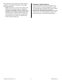
FIG. F: ELECTRIC BOX LOCATION
After removing attachment screws (Fig. E), tilt the bottom of the
electrical box to the right and slide it out. Set aside. It is not necessary
to disconnect any electrical cables.
FIG. E: ELECTRIC BOX
ATTACHMENT SCREWS
1. After placing a firm support under the base of the unit, remove
the center hub cap and remove the axle nut. The wheel will now
slide off. 2. Remove the two screws (shown in the circles above) to
detach the electric junction box.

110489R (07-01674) F410, F411 8 Legend Brands, Inc.
orientation. When installing the rear cover, carefully
thread the pump hose through the hole in the back
pocket before putting the cover in place.
NOTICE: Rubber strips are attached to the outside
edges of the evaporator and condenser coils to
provide an airtight seal around the heat exchange
block. When reinstalling the block, make sure the
seals are in place and are not kinked or folded.
TROUBLESHOOTING
FAULT CAUSE SOLUTION
Water drips out
when moving unit
Unit was unplugged before
purging was complete.
Purge unit before moving. See “At the End of the Job.”
Unit does not
operate
Unit not switched on.
No power to machine.
Switch unit on.
Plug in unit; check power cord connection at wall outlet and at
base of unit.
Unit operating,
but room not dry
Not enough time to dry.
Poor air movement in room.
Excessive moist air infiltration.
Make sure “Humidistat” is OFF.
Allow more time for drying.
Increase air movement with air movers.
Seal off area to reduce infiltration.
Unit collects too
little water
Room air is dry.
Room temperature is too low.
Filter is full.
Coils are clogged.
Make sure “Humidistat” is OFF.
Confirm humidity level with hygrometer.
Increase room temperature.
Check filter. Replace as necessary.
Check coils. Clean as necessary.
If the problem you are experiencing is not listed here, call your local distributor or contact
our Service Department at 800-932-3030 for further assistance.
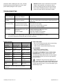
SPECIFICATIONS
Model LGR 2800i (F410) LGR 3500i (F411)
Use weight 156 lbs. | 70.8 kg 158 lbs. | 71.2 kg
Dimensions
(H × D × W)
40.5 × 23 × 24 in.
103 × 58 × 61 cm
40.5 × 23 × 24 in.
103 × 58 × 61 cm
Power
8.0 amps,
120 volts
11.2 amps,
120 volts
Water removal
AHAM (80°F/60%
RH)
130 pts. | 61.5 liters /
day
170 pts. | 80.4 liters /
day
Water removal max.
(90°F/90% RH)
200 pts. | 94.6 liters /
day
240 pts. | 113.6 liters
/ day
Water removal
80°F/20% RH
20 pts. | 9.5 liters /
day
24 pts. | 11.4 liters /
day
Max process air
400 CFM | 679.7
CMH*
400 CFM | 679.7
CMH*
Operating range
33°F–125°F
1°C–52°C
33°F–100°F
1°C–38°C
Construction
Rotomolded shell Rotomolded shell
Safety
ETL certified to CSA
22.2 no. 92
ETL certified to CSA
22.2 no. 92
Specifications are subject to change without notice. Some values may
be approximate. *Automatic variable speed for optimized
performance.
PARTS INCLUDED
40 ft. (12 m) of drain hose with quick-connect fitting.
25 ft. (7.6 m) detachable power cord.
4-PRO air filter. Reorder #121708 (F584) 24 pk.
ACCESSORIES
VMax Adaptor #100694 (F422)
Sto&Go Ducting #113260 (F405)
FOR PARTS AND SERVICE CALL YOUR LOCAL
DISTRIBUTOR or Dri-Eaz at 800-932-3030. Visit
warranty.LegendBrandsRestoration.com and register
your purchase to ensure you receive any important
product releases.
WARNING: This product may expose you to
chemicals, including lead and phthalates, known
to the State of California to cause cancer, birth defects,
or other reproductive harm. For more information, go to
P65Warnings.ca.gov

110489R (07-01674) F410, F411 9 Legend Brands, Inc.
Manual para el usuario
Deshumidificador Portátil LGR 2800i (F410)
Deshumidificador Portátil LGR 3500i (F411)
Legend Brands, Inc.
15180 Josh Wilson Road, Burlington, WA 98233
Teléfono: 800-932-3030 Fax: 360-757-7950 LegendBrandsRestoration.com
La serie de deshumidificadores Dri-Eaz
®
LGR iSeries reduce la humedad en ambientes
cerrados eliminando el vapor de agua que se encuentra en el aire. El modelo iSeries está
creado de modo que sea resistente, duradero y fácil de transportar, características que lo
convierten en un elemento sumamente adecuado para la reparación de daños causados por
el agua, el secado de estructuras, la construcción y otros usos para los que se necesita
temporalmente un deshumidificador de alto rendimiento.
Patents: LBpatents.com
LEA Y COMPRENDA ANTES DE OPERAR
INSTRUCTIONS DE SÉCURITÉ IMPORTANTES
ADVERTENCIA! Peligro de sufrir una descarga
eléctrica, lastimarse con el ventilador rotatorio y
quemarse con una superficie caliente. Desenchufe
la unidad antes de abrir la tapa para limpiarla o
hacerle mantenimiento. La unidad debe tener
descarga a tierra.
• Controle el cable de alimentación antes de usarlo.
Si está dañado, no lo use. Para desenchufar la
unidad, tire siempre del enchufe (nunca del
cable).
• Coloque el enchufe de tres clavijas que está en el
extremo del cable de alimentación en un
tomacorriente con descarga a tierra adecuado. No
use adaptadores. Nunca corte la tercera clavija.
No use cables prolongadores.
• La unidad debe utilizarse en un circuito eléctrico
de 115 V/60 Hz, protegido por un interruptor del
circuito de fallos de conexión a tierra (GFCI, por
sus siglas en inglés).
• No utilice el aparato en agua estancada.
Mantenga el motor y los cables secos.
AVISO: No lo utilice en entornos en los que haya
sustancias químicas corrosivas, como el cloro.
ANTES DE COMENZAR
Registro de la garantía
Visite warranty.LegendBrandsRestoration.com para
registrar su compra. El registro nos permite brindarle
mejor asistencia en el uso, el mantenimiento o la
reparación de su equipo, y también comunicarnos con
usted en caso de que tengamos información de
seguridad importante sobre su producto de Dri-Eaz.
Si
considera que su producto necesita reparación, tenga a
mano el modelo del equipo, el número de serie y el
comprobante de compra original, y llame a su
distribuidor para que lo ayude a obtener una
ADECUADO RETIRO DEL ENCHUFE
Tome el enchufe IEC y tire recto
IMPORTANTE: Cualquier daño en el
receptáculo IEC o en el deshumidificador
consecuencia de un inadecuado retiro del
cable eléctrico no será cubierto por la
garantía. El cable eléctrico IEC es un
elemento con desgaste y no está cubierto
por la garantía.
ADVERTENCIA

110489R (07-01674) F410, F411 10 Legend Brands, Inc.
autorización para devolver el producto (RMA, por sus
siglas en inglés).
INTRODUCCIÓN
Los deshumidificadores Dri-Eaz reducen la humedad en
ambientes cerrados eliminando el vapor de agua que se
encuentra en el aire. Si se usa correctamente, el
deshumidificador puede ayudar a secar alfombras,
almohadillas para alfombras, pisos, paredes, elementos
en el interior de una propiedad y más. También puede
ayudar a prevenir daños secundarios causados por el
exceso de humedad. Para obtener mejores resultados,
cuando use los deshumidificadores, coloque
ventiladores TurboDryer de Dri-Eaz alrededor del
perímetro de la habitación, a fin de distribuir la energía
térmica y hacer que la humedad de las superficies
mojadas se pierda en el aire.
Cómo funcionan los deshumidificadores
LGR
Los deshumidificadores refrigerantes de grano bajo
(LGR, por sus siglas en inglés) de Dri-Eaz hacen que el
aire húmedo atraviese un evaporador muy frío. La
humedad del aire se condensa en el serpentín. En
determinados momentos, la máquina funciona en modo
"descongelación", ya que calienta la escarcha
acumulada en el serpentín del evaporador y la convierte
nuevamente en agua. El agua se acumula en un
recipiente y se elimina por una manguera. Los sensores
integrados controlan permanentemente las condiciones
ambientales y las operaciones del sistema del
deshumidificador, incluidas la temperatura y la humedad
relativa, que pueden observarse en la pantalla de
visualización.
Los deshumidificadores refrigerantes de grano bajo
(LGR) poseen una mayor capacidad de intercambio de
calor y de descongelación que los deshumidificadores
refrigerantes normales; asimismo, pueden seguir
eliminando humedad en ambientes más secos.
DÓNDE COLOCAR UN
DESHUMIDIFICADOR
Para obtener mejores resultados, utilice su
deshumidificador en un espacio cerrado, lo que permite
crear una cámara de secado. A fin de aumentar al
máximo la eficacia de la unidad para eliminar el agua,
cierre todas las puertas y ventanas que den al exterior.
Además, trate de que el tránsito dentro de la cámara de
secado sea mínimo. Coloque su deshumidificador contra
una pared, lejos de cualquier elemento que lo obstruya,
y manténgalo alejado de cualquier objeto que pueda
bloquear el flujo de aire que entra y sale de la unidad.

110489R (07-01674) F410, F411 11 Legend Brands, Inc.
IDENTIFICACIÓN DE LAS PARTES
CÓMO USAR SU DESHUMIDIFICADOR
Coloque la unidad en posición vertical
AVISO: Si transporta un deshumidificador i-Series en
posición horizontal, enderécelo y déjelo en posición
vertical durante al menos 30 minutos antes de
prenderlo. Cuando la máquina está en posición
horizontal, el aceite del compresor fluye hacia los
serpentines refrigerantes, lo que disminuye la capacidad
de funcionamiento del deshumidificador. Dejar la unidad
en posición vertical durante 30 minutos permite que el
aceite vaya nuevamente hacia el compresor.
Coloque la manguera de drenaje
La bomba de condensado del modelo i-Series se
conecta a una manguera de drenaje plástica, ubicada en
la cavidad de la parte de atrás de la unidad. Dicha
manguera incluye un adaptador de conexión rápida para
ajustarla fácilmente a la manguera de drenaje de 40 pies
(12 m) proporcionada.
Desenrolle toda la manguera y
coloque el extremo suelto en una pila, un desaguadero,
un balde o afuera: en cualquier lugar donde el agua
FIG. C: PUNTOS DE CONEXIÓN DE
LA BOMBA Y LA ENERGÍA
Panel trasero inferior. Quite los cinco
tornillos que lo sostienen para sacar
la bomba y limpiarla.
FIG. D: PANEL DE ACCESO A LA BOMBA
Parte inferior del armazón
trasero de polietileno.
Quite los dos pernos para
sacar la bomba y
limpiarla.
Entrada del cable de
alimentación.
Panel de control.
Cavidad moldeada
para guardar el
cable.
Entrada de aire
húmedo (ambos
lados).
Salida de aire procesado
(deshumidificado). Puede
usarse con un conducto
estándar de 12" (30.5 cm)
rígido o plano.
FIG. A: PARTE DELANTERA
Armazón rotomoldeado
fuerte, resistente a
abolladuras y rayones, y
fácil de mantener.
FIG. B: PARTE TRASERA
Manija integrada.
Panel trasero inferior. Quítelo
para acceder a la bomba y realizar
tareas de mantenimiento.
Cavidad para guardar la
manguera de drenaje.

110489R (07-01674) F410, F411 12 Legend Brands, Inc.
pueda drenar de forma segura. Si acumula el agua en
un balde u otro recipiente, contrólelo con frecuencia
para evitar derrames.
NOTA: Desenrosque y estire toda la manguera de
drenaje. No deje ninguna parte de la manguera
enroscada en la unidad ni coloque el extremo de la
manguera a más de 20 pies (6 m) por encima de la
parte superior de la unidad. Controle también que
no haya dobleces u obstrucciones que impidan el
paso del agua. De lo contrario, es posible que la
bomba se tape y pierda agua.
Enchufe el cable eléctrico
El deshumidificador i-Series debe enchufarse en un
tomacorriente de 115 voltios, protegido por un GFCI,
con capacidad para 15 amperios como mínimo. Saque
el cable de la cavidad donde está guardado y
desenrósquelo. Conecte siempre primero y con firmeza
el cable que va a la unidad. Después, enchufe el otro
extremo del cable en un tomacorriente adecuado.

110489R (07-01674) F410, F411 13 Legend Brands, Inc.
CÓMO USAR EL PANEL DE CONTROL
El Controlador i-Series ofrece controles integrales para deshumidificadores y datos precisos en directo acerca del
ambiente que se está deshumidificando, además de las horas de funcionamiento, mensajes de autodiagnóstico,
recordatorios de mantenimiento y el estado operativo.
Para obtener información detallada e instrucciones adicionales, visite la página del Controlador i-Series en
Controller.LegendBrandsRestoration.com
.
Visualizaciones de la pantalla principal
Unidad APAGADA
La unidad debe estar enchufada.
Barra superior de la pantalla:
Horas de funcionamiento, hora actual
Presione MENÚ para acceder a los controles
de ajustes y configuraciones
Presione PURGA para vaciar el tanque de
condensado
Presione ENCENDER/APAGAR para encender
la unidad
Unidad ENCENDIDA
Presione la tecla ENCENDER/APAGAR para encender
la unidad.
Barra superior de la pantalla:
Horas de funcionamiento, hora actual
Pantalla de información:
Temperatura de entrada/salida, % de HR y granos de
humedad por libra de aire seco (GPP)
Eliminación de los GPP actuales
Barra inferior del menú:
GPP de entrada de referencia rápida.
1: <60 GPP; 2: 60–90 GPP; 3:> 90 GPP
Presione MENÚ para acceder a los controles
de ajustes y configuraciones
Presione PURGA para vaciar el tanque de
condensado
Presione ENCENDER/APAGAR para apagar la
unidad

110489R (07-01674) F410, F411 14 Legend Brands, Inc.
ERRORES Y ADVERTENCIAS
Si el sistema de control detecta un problema, mostrará un símbolo de "Alerta" en la esquina superior derecha de la
pantalla. Presione ON / OFF para ver el mensaje y OK para borrar el mensaje. NOTA: En caso de error, la unidad no
funcionará hasta que se resuelva el problema. Consulte las explicaciones y soluciones que se muestran a continuación.
Si estas soluciones no solucionan el problema, comuníquese con su centro de servicio autorizado local para obtener más
ayuda.
MENSAJE DEL PANEL
DE CONTROL
EXPLICACIÓN Y SOLUCIÓN
ER4 Error
Conexion de Termistor de Desconjelar
—or—
Conexion de Termistor de Salida
El sensor de temperatura está abierto, no está o hay un cortocircuito.
Verifique que los sensores de temperatura están instalados correctamente
en el panel de control. Si el error continúa, comuníquese con el servicio
técnico
ER5 Error
Sensor de Entrada RH1 Temp/RH
El sensor de temperatura/humedad relativa de entrada está abierto, no está
o hay un cortocircuito. Verifique que el sensor de temperatura/humedad
relativa de entrada esté instalado correctamente en el panel de control y la
cubierta de entrada. Si el error continúa, comuníquese con el servicio
técnico.
ER6 Error
Falla de Sensor de Energía
Falla del sensor de corriente. Si el error continúa, comuníquese con el
servicio técnico.
ER9 Error
Bomba Obstruida
Compruebe que no haya obstrucciones ¿La manguera está acodada debajo
de la unidad o aplastada por una rueda? Verifique que no haya bloqueos en
la bomba y repare de ser necesario.
W1
Bajo BATERÍA
Reemplace la batería de tipo botón (3V, CR2032) en el panel de control.
W2
BLE Error
W3
Reinici Flash
W4
WDT
Apague y encienda el deshumidificador. Si la advertencia persiste,
comuníquese con el servicio.

110489R (07-01674) F410, F411 15 Legend Brands, Inc.
AL FINALIZAR EL TRABAJO
Para reducir la posibilidad de goteos al mover la
unidad, siga estos pasos adicionales para
asegurarse de que toda el agua sea retirada de la
unidad.
AVISO: Para asegurar que toda el agua sea quitada del
deshumidificador, la unidad habrá de completar el ciclo
de descongelamiento incluso si se halla apagada. Si la
unidad fuera desenchufada durante el ciclo de
descongelamiento, es posible que se acumule en la
misma el exceso de agua y gotear cuando se la
traslade.
AVISO: Para asegurarse de que el tanque de
condensado se vacíe por completo mientras se hace el
purgado, asegúrese de que la unidad esté en posición
vertical sobre una superficie horizontal.
1. Si la unidad está en un ciclo de
descongelamiento, espere hasta que regrese al
modo normal de funcionamiento antes de proceder.
2. Mueva suavemente la máquina para asegurarse
de que cualquier resto de agua en las superficies
interiores caiga en el área del colector.
3. Pulse la tecla de PURGADO. Cuando se complete
el ciclo de purgado, apague la unidad.
4. Desconectar el tubo de drenaje externo, escurrir
con cuidado, enrollarla y fijarlo en el bolsillo o en la
correa suministrada con la unidad.
MANTENIMIENTO
¡ADVERTENCIA! PELIGRO DE DESCARGA
ELÉCTRICA. Desenchufe el deshumidificador antes
de realizar cualquier tarea de mantenimiento.
Antes de cada uso
Controle el cable eléctrico para detectar daños.
Fíjese que el cable no esté pelado, cortado, etc. No use
la unidad si detecta algún daño. Para conocer el Centro
de Servicio Técnico más cercano, llame a Dri-Eaz al
800-932-3030.
Controle y aspire el filtro cuando sea necesario. Los
deshumidificadores i-Series están equipados con un
filtro para alto flujo de aire 4-PRO #121708 (F584). El
filtro para 4-PRO se puede limpiar con aspiradora y
volver a usar hasta tres veces. No enjuague ni lave el
filtro para 4-PRO, ya que reducirá la eficacia del
material electrostático.
Tenga siempre un filtro limpio en la unidad para proteger
los componentes internos contra la acumulación de
polvo y otras partículas. Aspire o cambie el filtro antes
de cada trabajo. Reemplácelo únicamente con un filtro
para 4-PRO nuevo (pieza n.º 121708 de Dri-Eaz). Para
solicitar piezas y servicio técnico, llame al distribuidor de
su zona o al Departamento de Servicio Técnico de Dri-
Eaz, al 800-932-3030 ó 360-757-7776.
ADVERTENCIA: El polvo puede hacer que la
unidad se recaliente y se apague.
No utilice el
equipo cuando haya exceso de polvo o partículas en
el aire, por ejemplo durante el lijado o la pintura con

110489R (07-01674) F410, F411 16 Legend Brands, Inc.
pulverizador. Controle y limpie los serpentines y los
componentes del filtro de aire con frecuencia.
IMPORTANTE: Reemplace el filtro para 4-PRO
cuando haya sido utilizado en tareas de
eliminación de moho o haya sido expuesto a
sustancias contaminantes potencialmente
peligrosas.
Una vez al mes
Controle los serpentines. Los serpentines sucios
pueden hacer que la unidad se recaliente. Límpielos
cuando los note sucios. Consulte las instrucciones de
limpieza en la página 17.
Controle el bloque de intercambio de calor. Límpielo
con aire comprimido únicamente. Tenga cuidado de no
dañar el bloque.
Controle y limpie la bomba. Para quitar la bomba de
condensado, haga lo siguiente:
MANTENIMIENTO DE LA BOMBA Y LA BANDEJA DE
DRENAJE
A fin de que la unidad siga
funcionando
correctamente, debe retirar
y limpiar la bomba y la
bandeja de drenaje
periódicamente; para
hacerlo, siga estos pasos:
Herramientas necesarias
Destornillador Phillips
Destornillador de punta
plana
Tubos de ⅜ y
15
∕
16
pulgadas (9.5 y 24 mm)
y llave de tubos
Trapos
DESARMADO Y
LIMPIEZA
1. Desenchufe la unidad y
luego retire el cable de
alimentación de la entrada
que está en la base de la
unidad. Saque la
manguera de la bomba de
la conexión rápida.
2. Quite el filtro para 4-
PRO.
3. Quite los dos pernos de
la tapa superior del frente.
4. Quite el perno de cada
esquina trasera superior de
las tapas laterales A y B
(vea la Figura A).
5. Quite los cuatro pernos
del panel trasero inferior;
ahora puede retirar el
panel trasero/superior.
6. Retire el panel metálico trasero inferior (desenrosque
los cinco tornillos restantes).
7. Coloque un soporte firme debajo de la base de la
unidad para sacar la rueda izquierda.
8. Con el destornillador de punta planta, afloje
cuidadosamente el tapacubos central de la rueda
izquierda. Use el tubo de
15
∕
16
pulgadas para sacar la
tuerca de retención y deslizar la rueda hacia afuera. Vea
la Figura E, #1.
9. Quite los dos tornillos de retención de la caja eléctrica
(vea la Figura E, #2).
10. Incline la parte de abajo de la caja eléctrica hacia la
derecha y deslícela hacia afuera (Figura F). No es
necesario que desconecte ningún cable eléctrico.
11. Saque la manguera de drenaje de la bomba y
deslice la bomba y la bandeja hacia fuera de la unidad.
12. Levante la estructura de la bomba para sacarla de la
bandeja plástica de recolección y aparte la bomba.
LIMPIEZA DE LA BOMBA Y LA BANDEJA DE LA
BOMBA
13.
Enjuague o limpie con un trapo húmedo todas las
superficies de la bandeja plástica de recolección.
Tapa trasera.
Tapa lateral A.
Tapa lateral B.
Filtro de aire para 4-PRO.
FIG. G: LIMPIEZA
Antes de volver a colocar la tapa,
pase la manguera de la bomba por el
agujero que hay en la parte de abajo
de la cavidad trasera para la
manguera.
Serpentín
condensador.
Serpentín (frío) evaporador.
Bloque de intercambio
de calor de aire a aire.
Las flechas impresas en
el bloque indican el
sentido correcto de la
instalación.

110489R (07-01674) F410, F411 17 Legend Brands, Inc.
14. Limpie con un trapo húmedo todas las superficies de
la bomba.
15. Saque la manguera de bombeo de la salida de la
válvula de retención.
16. Desenrosque la válvula de retención. Con una pinza
de punta de aguja, quite cuidadosamente la parte de
abajo de la válvula de retención; para hacerlo,
introduzca un lado de la pinza en el agujero a unas ⅛
pulgadas (3 mm), apriete y retire con cuidado. Es
probable que salga un soporte de bolas; tenga cuidado
de no perderlo. Inspeccione la unidad y límpiela
conforme sea necesario. Vuelva a colocar el soporte de
bolas y la válvula de retención.
Vuelva a armar la unidad siguiendo los pasos anteriores
a la inversa. El deshumidificador está listo para usar.
Una vez al año
Llame al Departamento de Servicio Técnico de Dri-Eaz
(800-932-3030) o a un centro de servicio técnico
habilitado para que controle el sistema de la bomba.
TRANSPORTE Y ALMACENAMIENTO
AVISO: Manipule la unidad con cuidado. No la tire ni la
apoye en lugares donde pueda caerse. Si no trata este
equipo con cuidado, puede dañarse y ocasionar algún
peligro, o la garantía puede quedar anulada.
• No exponga el panel de control a humedad, nieve o
lluvia cuando lo transporte en vehículos
descubiertos, tales como los camiones de
plataforma.
• Transpórtelo y almacénelo de manera segura para
evitar cualquier impacto que dañe las partes
internas.
LIMPIEZA DE LOS SERPENTINES Y DEL
BLOQUE DE INTERCAMBIO DE CALOR
¡Advertencia! Desenchufe la unidad antes de
realizar cualquier tarea de mantenimiento.
Para contribuir a que la unidad siga funcionando
eficazmente, mantenga limpios los serpentines y el
bloque de intercambio de calor de aire a aire. Se puede
acceder fácilmente a estos componentes quitando las
tapas laterales y trasera de la unidad, tal como se
describe a continuación:
1. Desenchufe la unidad.
2. Desconecte el cable de alimentación de la entrada
que está en la base de la unidad. Saque la manguera
de la bomba de la conexión rápida.
3. Quite el filtro para 4-PRO.
4. Saque las dos tapas laterales A y B (desatornille los
dos pernos que hay en cada panel).
5. Saque la tapa trasera (desatornille los cuatro
pernos que hay en la parte de atrás y los dos pernos
del panel superior del frente).
6. Quite el bloque de intercambio de calor.
Controle con cuidado el bloque de intercambio de calor.
De ser necesario, use aire comprimido para limpiar las
canaletas del bloque, con cuidado para no dañarlo.
AVISO: La unidad está equipada con sensores
electrónicos sensibles. Proteja los sensores contra
impactos y no los exponga a agua ni a ninguna
solución de limpieza.
Se puede usar un producto limpiador de serpentines en
el serpentín frío horizontal (evaporador) solamente. Siga
las instrucciones en la etiqueta del producto. Tenga
cuidado de no rociar o limpiar el producto sobre o cerca
de componentes eléctricos o sensores. Para limpiar la
bobina vertical (condensador), comuníquese con el
Servicio para obtener instrucciones.
Para volver a armar siga los pasos anteriores, pero a la
inversa. Asegúrese de volver a instalar el bloque de
intercambio de calor según la orientación que tenía
originalmente. Antes de volver a colocar la tapa trasera,
pase con cuidado la manguera de la bomba por el
agujero que hay en la cavidad de la parte de atrás.
AVISO: Los bordes exteriores de los serpentines
evaporadores y condensadores tienen burletes de
goma que crean un cierre hermético alrededor del
bloque de intercambio de calor. Cuando vuelva a
instalar el bloque, asegúrese de que los burletes estén
en el lugar correspondiente y no estén torcidos ni
doblados.

110489R (07-01674) F410, F411 18 Legend Brands, Inc.
ESPECIFICACIONES
Modelo
LGR 2800i (F410)
LGR 3500i (F411)
Peso
156 lbs. | 70.8 kg
158 lbs. | 71.2 kg
Dimensiones (altura
× profundidad ×
ancho)
48.5 × 23 × 24 in
103 × 58 × 61 cm
48.5 × 23 × 24 in
103 × 58 × 61 cm
Potencia
8.0 A, 120 V
11.2 A, 120 V
Eliminación de
agua según AHAM
(80 °F [26.5
ºC]/60% de
humedad relativa)
130 pt | 61.5 por día 170 pt | 80.4 l por día
Eliminación de
agua máxima (90
°F [32 ºC]/90% de
humedad relativa)
200 pt | 94.6 por día 240 pt | 113.6 por día
Eliminación de
agua (80 °F
[26.5 ºC]/20% de
humedad relativa)
20 pts. | 9.5 l por día 24 pt | 11.4 l por día
Cantidad máxima
de aire procesado
400 cfm | 679.7 m
3
/h*
400 cfm | 679.7 m
3
/h*
Rango de
temperatura de
operación
33°F–125°F
1°C–52°C
33°F–100°F
1°C–38°C
Construcción
Carcasa rotomoldeada
Carcasa rotomoldeada
Seguridad
Certificación de ETL
conforme a las normas
CSA 22.2 n.º 92
Certificación de ETL
conforme a las normas
CSA 22.2 n.º 92
Las especificaciones están sujetas a cambios sin previo aviso. Algunos
valores pueden ser aproximados.
* Velocidad variable automática para optimizar el desempeño.
PIEZAS INCLUIDAS
40 ft. (12 m) Manguera de desagüe de 40 pies (12 m)
con conexión de acoplamiento rápido.
25 ft. (7.6 m) Cable de alimentación extraíble
4-PRO filter #121708 (F584) (24 pk.)
ACCESSORIES
VMax Adaptor #100694 (F422)
Sto&Go Ducting #113260 (F405)
PARA PEDIR INFORMACIÓN SOBRE PIEZAS Y
SERVICIO, LLAME A SU DISTRIBUIDOR LOCAL o a
Dri-Eaz al 800-932-3030.LegendBrandsRestoration.com
Visite el sitio warranty.LegendBrandsRestoration.com y
registre su compra para garantizar que reciba
información sobre los lanzamientos de productos
importantes.
ADVERTENCIA: Este producto puede exponerlo
a sustancias químicas entre las que se incluyen
plomo y ftalatos, los cuales son considerados en el
estado de California como causantes de cáncer,
defectos congénitos u otros daños durante la gestación.
Para obtener más información, visite
P65Warnings.ca.gov

110489R (07-01674) F410, F411 19 Legend Brands, Inc.
Guide d’utilisation
Déshumidificateur portable LGR 2800i (F410)
Déshumidificateur portable LGR 3500i (F411)
Legend Brands, Inc.
15180 Josh Wilson Road, Burlington, WA 98233 (États-Unis)
Téléphone : 800-932-3030 Fax : 360-757-7950 LegendBrandsRestoration.com
La gamme de déshumidificateurs Dri-Eaz
®
LGR « i » réduit l’humidité dans les
environnements structurels fermés en éliminant la vapeur contenue dans l’air. La gamme
« i » est conçue pour être robuste, durable, facilement transportable et, par conséquent, ces
appareils sont les outils parfaits pour les restaurations à la suite de dégâts causés par l’eau,
pour le séchage structurel et la construction, ainsi que pour d’autres applications exigeant
une déshumidification temporaire à hautes performances.
Patents: LBpatents.com
CONSERVER CES INSTRUCTIONS
INSTRUCTIONS DE SÉCURITÉ IMPORTANTES
AVERTISSEMENT! Ne pas modifier d’aucune façon.
Utiliser seulement des pièces de rechange
autorisées par Dri-Eaz Products, Inc. Toute
modification ou l’utilisation de pièces non
approuvées peut constituer un danger et
annulera votre garantie. Contactez votre
distributeur autorisé Dri-Eaz pour obtenir de
l’aide.
AVERTISSEMENT! Danger de décharge
électrique, ventilateur tournant et surfaces très
chaudes.
Débrancher l’appareil avant d’ouvrir le
couvercle pour le nettoyage ou l’entretien.
L’appareil doit être mis à la terre.
• Vérifier l’état du cordon d’alimentation avant
utilisation. Ne pas l’utiliser si le cordon est
endommagé. Pour débrancher, toujours saisir
la prise (et non le cordon).
• Enfoncer les trois fiches de la prise du cordon
dans une prise de courant mise à la terre. Ne
pas utiliser d’adaptateur. Ne jamais sectionner
la troisième fiche. Ne pas utiliser de rallonge.
• L’appareil doit fonctionner sur un circuit de
115V/60 Hz protégé par un disjoncteur de fuite
à la terre.
• Ne pas mettre l’appareil en marche lorsque de l’eau
stagne en surface. Le moteur et le câblage doivent
rester secs.
AVIS: Ne pas utiliser dans des environnements
contenant des produits chimiques corrosifs, tels que
le chlore.
PRÉLIMINAIRES
Enregistrement de la garantie
Enregistrez votre appareil sur le site
warranty.LegendBrandsRestoration.com.
L’enregistrement nous aidera à vous donner des
conseils judicieux quant à l’utilisation, l’entretien ou la
réparation de votre appareil et de vous contacter au cas
où nous aurions des renseignements importants en
AVERTISSEMENT
COMMENT BIEN ENLEVER
LE CORDON ÉLECTRIQUE
Saisir la prise IEC et tirer en la tenant droite
IMPORTANT : Les dommages occasionnés au
récipient ou au déshumidificateur IEC en raison
d’un retrait incorrect du cordon électrique ne sont
pas couverts par la garantie. Le cordon électrique
IEC étant une pièce d’usure, il n’est pas couvert
par la garantie.

110489R (07-01674) F410, F411 20 Legend Brands, Inc.
matière de sécurité touchant à votre produit Dri-Eaz. Si
vous estimez qu’une réparation s’impose, procurez-vous
le modèle de l’appareil, le numéro de série et la preuve
d’achat originale, puis appelez votre distributeur pour
obtenir une autorisation de retour d’article (RMA).
INTRODUCTION
Les déshumidificateurs Dri-Eaz réduisent l’humidité dans
les environnements structurels fermés en éliminant la
vapeur d'eau contenue dans l’air. Lorsqu'ils sont utilisés
correctement, les déshumidificateurs peuvent aider à
sécher les moquettes, les sous-tapis, les planchers, les
murs, le contenu d’un bâtiment, et bien plus. L’utilisation
de déshumidificateurs DriEaz peut également aider à
prévenir des dommages secondaires causés par des
taux d’humidité élevés. Pour obtenir les meilleurs
résultats possibles, utilisez les déshumidificateurs avec
les appareils aérauliques TurboDryer de Dri-Eaz, en les
plaçant sur le périmètre de la pièce afin de distribuer
l’énergie thermique et de dégager l’humidité provenant
des surfaces mouillées dans l’air.
Fonctionnement des déshumidificateurs
de la gamme LGR
Les déshumidificateurs réfrigérants à grains Dri-Eaz
fonctionnent en attirant l’air humide à travers un noyau
d’évaporation extrêmement froid. L’humidité de l’air se
condense sur le serpentin. Sous certaines conditions,
l’appareil fonctionne en mode de dégivrage, réchauffe
tout le givre qui aurait pu s’accumuler sur le serpentin de
l’évaporateur et le transforme en eau. L’eau est recueillie
dans un plateau et est pompée à travers un tuyau. Les
capteurs incorporés surveillent continuellement les
conditions ambiantes et le fonctionnement du système
de l’humidificateur, y compris la température et
l’humidité relative; ces données peuvent être visualisées
sur le panneau d'affichage.
Les déshumidificateurs réfrigérants à grains (LGR - Low
Grain Refrigerant) offrent de meilleures capacités
d’échange thermique et de dégivrage que les
déshumidificateurs standard réfrigérants. Ils peuvent
donc continuer à éliminer l’humidité dans des
atmosphères plus sèches.
MISE EN PLACE D’UN
DÉSHUMIDIFICATEUR
Pour obtenir les meilleurs résultats possibles, faites
fonctionner vos déshumidificateurs dans une zone
fermée, vu que ceci crée une chambre de séchage.
Fermez toutes les portes et toutes les fenêtres qui
s’ouvrent vers l’extérieur afin de permettre à l’appareil
d’éliminer l’eau de manière la plus efficace possible.
Assurez-vous également que les allées et venues dans
la chambre de séchage sont rares. Placez le
déshumidificateur contre un mur, loin de toute
obstruction, et loin de tout objet qui pourrait bloquer le
débit d’air qui entre et sort de l’appareil.
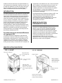
IDENTIFICATION DES PIÈCES
FIG. A : AVANT
Panneau de commande
Réceptacle moulé
pour rangement du
cordon.
Entrée d’air humide
(2 côtés)
Sortie d’air traité
(déshumidifié). Peut être
utilisé avec des conduits
plats ou rigides standard de
12 po
Boîtier rotomoulé
solide résistant aux
bosses et aux rayures
et d’entretien aisé
FIG. B : ARRIÈRE
Poignée intégrée
Panneau arrière inférieur.
Retirez-le pour accéder à la
pompe à des fins d’entretien.
Réceptacle de tuyau
de vidange
La page est en cours de chargement...
La page est en cours de chargement...
La page est en cours de chargement...
La page est en cours de chargement...
La page est en cours de chargement...
La page est en cours de chargement...
-
 1
1
-
 2
2
-
 3
3
-
 4
4
-
 5
5
-
 6
6
-
 7
7
-
 8
8
-
 9
9
-
 10
10
-
 11
11
-
 12
12
-
 13
13
-
 14
14
-
 15
15
-
 16
16
-
 17
17
-
 18
18
-
 19
19
-
 20
20
-
 21
21
-
 22
22
-
 23
23
-
 24
24
-
 25
25
-
 26
26


Dri-Eaz F410 LGR 2800i Portable Dehumidifier Manuel utilisateur
- Catégorie
- Déshumidificateurs
- Taper
- Manuel utilisateur
dans d''autres langues
Documents connexes
-
Dri-Eaz LGR i-Series Le manuel du propriétaire
-
Dri-Eaz LGR i-Series Le manuel du propriétaire
-
-
-
-
-
-
-
Dri-Eaz Dri-Pod F451 Le manuel du propriétaire
-
