Ideal 61-327 Manuel utilisateur
- Catégorie
- Mesure, test
- Taper
- Manuel utilisateur

Instrucciones en español adentro / Instructions en français à l’intérieur
61-327 Multimeter
Operation and Safety Manual
IDEAL
®
Test and Measurement

Introduction ................................................................... 3
Contacting IDEAL INDUSTRIES, INC ...................................... 3
Safety Information ........................................................... 4
Warnings ..............................................................................................4-5
Cautions ...................................................................................................5
Symbols ............................................................................................... 6-7
Operation.................................................................. 8-19
Identification and description of operating controls and
functions ............................................................................................. 8-9
Operating Features ........................................................................... 10-11
Using Test Leads ....................................................................................12
Meter Operation ..............................................................................13-16
Non-Contact Voltage Testing ..........................................................13
Measuring Voltage .........................................................................14
Measuring Continuity .....................................................................15
Measuring Resistance ....................................................................15
Measuring Diodes ..........................................................................16
Testing a Battery .............................................................................16
Functions Operation Table ......................................................................17
Functions Indication Table .....................................................................18
Electrical Specifications .........................................................................19
Environmental Specifications .............................................20
Mechanical Specifications ................................................20
EMC / EMI ....................................................................20
FCC .........................................................................21
Safety .........................................................................21
Maintenance and Service .............................................22-23
Table of Contents
2

Introduction
The IDEAL
®
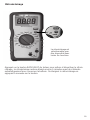
61-327 Digital Multimeter is a manual ranging average RMS meter
that measures voltage, resistance, continuity, diodes and performs a battery check
via test-leads in the designated terminals. It also detects the presence of voltage
between 40V to 600V AC via a non-contact sensor in the top center of the meter.
3
Arc Flash and Shock Hazard, Proper PPE Required. Follow all safety procedures,
wear proper PPE in accordance to NFPA 70E. Read and fully understand the
instruction manual prior to using this product. Failure to comply can result in
serious injury or death.
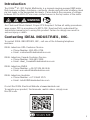
Contacting IDEAL INDUSTRIES, INC.
To contact IDEAL INDUSTRIES, INC., call one of the following telephone
numbers:
IDEAL Industries USA Customer Service
• Phone Number: 800-435-0705
• Email: [email protected]
IDEAL Industries Canada Customer Service
• Phone Number: 905-683-3400
• Email: [email protected]
IDEAL Industries EMEA
• Phone Number: +44 (0)1925 444 446
• Email: eur[email protected]
IDEAL Industries Australia
• Phone Number: +61 3 9562 0175
• Email: [email protected]
Or visit the IDEAL Electrical Website at www.idealind.com
To register your product, find manuals, watch videos, simply scan
this QR code.

WARNING
Safety Information
Arc Flash and Shock Hazard, Proper PPE Required. Follow all safety procedures,
wear proper PPE in accordance to NFPA 70E and follow the guidelines below and the
instructions in this manual when operating the meter. Failure to comply can result in
serious injury or death.
• Choking Hazard, Small Parts. Keep Away from Children. Sharp Objects
Hazard, This is not a toy. It is not for use or play by children. Keep Away
from Children. Failure to do so can result in serious injury.
• Only experienced or technically competent consumers should use this
equipment. When in doubt, call an experienced electrician to make any and
all necessary repairs or installations. At all times, perform any necessary
work on a de-energized circuit that has had its circuit breaker turned off and
has been locked out.
• Use the Meter only as specified in this manual or protection provided by the
Meter can be compromised.
• Before using or connecting the Meter, visually inspect it to ensure the cases
are not cracked and the back case is securely in place. Do not use if the
Meter appears damaged.
• Before using the test leads, inspect carefully for damaged insulation,
exposed metal or cracked probes. Check test leads for continuity. Do not use
leads if they appear damaged.
• Use only approved test leads. Do not use improvised connections that could
present a safety hazard.
• When using the probes, keep fingers behind the guard ring on the probes.
• Connect the common test lead before connecting the live test lead. When
disconnecting test leads, disconnect the live test lead first.
• This Meter is intended for use by qualified electricians. Follow NFPA 70E
Standards for Electrical Safety in the Workplace when using this Meter.
• Do not use without the batteries correctly in place and the battery door
closed and secured.
• Do not use Meter if it operates incorrectly as protection may be
compromised. When in doubt, have the Meter serviced.
• When servicing the Meter, use only specified replacement parts.
4
Warning - Identifies conditions and actions that could result in
possible death or serious injury if the hazard is realized.
Caution - Identifies conditions and actions that could result in meter dam-
age, equipment under test damage or data loss if the hazard is realized.

5
Arc Flash and Shock Hazard, Proper PPE Required. Follow all safety procedures,
wear proper PPE in accordance to NFPA 70E and follow the guidelines below and
the instructions in this manual when operating the meter. Failure to comply can
result in serious injury or death.
• Have the Meter serviced only by qualified service personnel.
• Do not use the Meter around explosive gas, dust, or vapor, or during electrical
storms, or in wet environments.
• When measuring, keep fingers behind the Tactile Barrier. See “The Meter” on
pg. 8 and 9.
• Do not apply more than the rated voltage, as marked on the Meter, between the
terminals or between any terminal and earth ground.
• To avoid false readings that can lead to electrical shock and injury, replace the
batteries as soon as the low battery indicator ( ) appears.
• Remove the test leads from the circuit prior to removing the battery door.
• Voltages exceeding 30VAC or 60VDC pose a shock hazard so use caution.
• Always ensure that test leads are secured so that they cannot be accidentally
snagged or tripped over.
• Do not work alone so that assistance can be rendered in an emergency.
• Use extreme caution when working around bare conductors or bus bars. Contact
with the conductor could result in electric shock.
• Adhere to local and national safety codes. Individual protective equipment must
be used to prevent shock and arc blast injury where hazardous live conductors
are exposed.
• Disconnect circuit power and discharge all high-voltage capacitors before you
measure resistance, continuity, or capacitance.
• Never operate the Meter with the back cover removed or the case open.
• Cancer and Reproductive Harm - www.P65Warnings.ca.gov
Meter damage, equipment under test damage or data loss can occur
if the following guidelines are not adhered to.
• Use the proper terminals, function, and range for the measurement
application.
• Clean the case and accessories with a damp cloth and mild detergents only.
Do not use abrasives or solvents. Make sure the meter is completely dry
before use.
CAUTION
WARNING

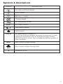
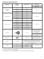
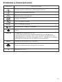
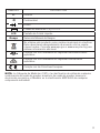
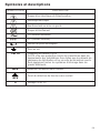
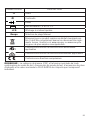
Symbols & Descriptions
SYMBOL DESCRIPTION
Arc Flash and Shock Hazard
Shock Hazard
Warning or Caution
Choking Hazard
AC (Alternating Current)
DC (Direct Current)
Low Battery Indicator
Earth Ground
CAT III
IEC Measurement Category III
CAT III has protection against transients in equipment in fixed-
equipment installations such as distribution panels feeders,
and short branch circuits. Also included are lighting systems in
larger buildings.
NCV
Non-Contact Voltage Sensing
NCV
Non-Contact Voltage Sensing Point
V
Voltage AC or DC
6

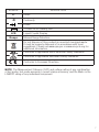
SYMBOL DESCRIPTION
Ω
Ohms
Continuity
Diode
1.5 and 9V DC Battery Test
LCD Liquid Crystal Display
Range Manual Range Selection
Do not dispose of this product as unsorted municipal waste.
It must be properly disposed of in accordance with local
regulations. Please see www.epa.gov or www.erecycle.org for
additional information.
Conforms to applicable North American Safety Standards
Conforms to applicable Australian Safety Standards
Conforms to European Directives
NOTE: The Measurement Category (CAT) and voltage rating of any combination
of test probe, test probe accessory, current clamp accessory, and the Meter is the
LOWEST rating of any individual component.
7

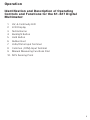
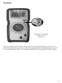
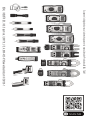
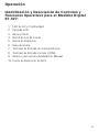
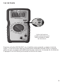
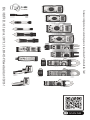
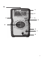
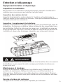
Identification and Description of Operating
Controls and Functions for the 61-327 Digital
Multimeter:
1. HV, & Continuity LED
2. LCD Display
3. Tactile Barrier
4. Backlight Button
5. Hold Button
6. Rubber Boot
7. Volts/Ohms Input Terminal
8. Common (COM) Input Terminal
9. Manual Measuring Functions Dial
10. NCV Sensing Point
8
Operation

4
1
3
7
9
2
5
6
9
8
10

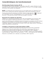
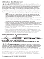
High Voltage Warning (HI-V)
The meter beeps once (for 1 second) and a red LED illuminates and remains on as
long as the voltage remains above 30V AC or DC, or when the meter’s voltage range
is exceeded.
NOTE: This feature does not work in the Ohm or continuity modes. For ACV and
DCV, when voltages in excess of 30V is measured or the measured voltage is over
limit, then the high voltage alarm ‘ .’ appears on the screen display,
simultaneously the LED remains RED and beeping lasts for 1 second then silent
during measurement.
Data Hold Feature
Press the Hold button to toggle in and out of the data hold mode. “H” appears in the
upper left of the meter display when data hold is active. Use the data hold feature to
lock a measurement reading on the display. Press the Hold button again to unlock
the display and obtain a real-time reading.
Auto Power Off (APO) Feature Disable
The meter automatically powers itself down after about 30 minutes of no use. Press
any button, and the meter will wake up and enter the default function of that setting
before power down. To Disable APO, press and hold the HOLD button while turning
the dial to any desired function. When APO is defeated, the “APO” will be removed
from the display. Turning the meter off and back on will restore the APO default.
10
Operating Features

11
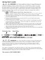
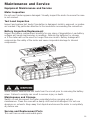
Press the BACKLIGHT button on the meter to turn the backlight on and off. The
white backlight will remain lit for about 5 minutes before it automatically turns off
to conserve battery power. Or turn the backlight off by pressing the button again.
Backlight
Backlight is selectable
to be on in all
functions.

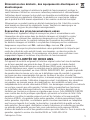
WARNING: Arc Flash and Shock Hazard, Proper PPE Required.
Follow all safety procedures, wear proper PPE in accordance to NFPA 70E and
assure that the Protective Caps are in place when operating a properly rated
electrical meter/tester using the TL-757 Test Leads in a CAT IV 600V or CAT III
1000V environment.
This meter is intended for use with the IDEAL TL-757 lead set (provided with this
product) or equivalent. The lead set must comply with requirements for Overvoltage
and Measurement Categories CAT IV 600V CAT III 1000V.
12
Using Test Leads
WARNING: Arc Flash and Shock Hazard, Proper PPE Required.
Follow all safety procedures, wear proper PPE in accordance to NFPA 70E and
follow the guidelines below and the instructions in this manual when operating
the meter with TL-757 Test Leads or equivalent. Test Leads must be rated for the
electrical environment the meter is being used in and have a voltage rating of at
least the voltage of the circuit to be measured. Failure to comply can result in
serious injury or death.
• Choking Hazard, Small Parts. Keep Away from ...
Children. Sharp Objects Hazard, This is not a toy. It is not for use or
play by children. Failure to do so can result in serious injury or death.
• Use only approved test leads. Do not use improvised connections that could
present a safety hazard.
• Ensure that the test leads are inserted into the correct input jacks when
measuring AC or DC current.
• Prior to using the test leads, inspect them carefully for damaged insulation,
exposed metal or bent probes. Check test leads for continuity. Do not use
leads if they appear damaged.
• When using the probes, keep fingers behind the guard rings on the probes.
• Connect the common test lead before connecting the live test lead. When
disconnecting test leads, disconnect the live test lead first.
• Always ensure that test leads are secured so that they cannot be accidentally
snagged or tripped over.
This meter is CAT III 600V ONLY
Note: The 61-327 is only rated to 600V AC or DC MAX
Protective Cap Guard Ring
CAT III 1000V, CAT IV 600V (with cap on)
WARNING: To prevent possible electrical shock or personal injury, the
protective caps must be in place when operating a properly rated electrical meter/
tester using the TL-757 Test Leads in a CAT IV 600V or CAT III 1000V environment.

Meter Operation
13
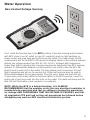
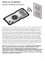
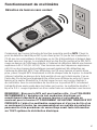
Non-Contact Voltage Sensing
First, rotate the function key to the NCV position. Place the sensing point marked
with NCV close to an AC outlet (or any AC conductor such as light switches or
power cords) and scan back and forth across the outlet. The meter beeps On/Off
continuously and the Red NCV LED above the display flashes if the sensing antenna
detects live voltage greater than 40V AC (50 -60 Hz). Voltages with frequencies
higher than 60Hz or electrostatic charges may also be detected by the NCV sensing
antenna. To differentiate between hot and neutral in an outlet, place the NCV tab
directly next to each slot in the outlet. The tone (buzzer) will sound over the slot
that is energized and not on the neutral slot. Either test lead can also be used to
differentiate between the hot and neutral. Plug the red or black test lead into the
V input jack on the meter. With the function switch in the NCV position, insert the
probe end of just one probe into the slots on the outlet. The meter will beep and the
Red LED will flash when a hot conductor is contacted.
NOTE: While the NCV is a helpful function, it is ALWAYS
RECOMMENDED that the operator verify that any electrical conductor is
completely de-energized and that no voltage is present by measuring
for voltage AND CONFIRMING THAT NO VOLTAGE IS PRESENT and that
all applicable PPE and lock out tag out procedures be followed before
attempting any work on ANY electrical distribution system.
Note: The 61-327 is only rated to 600V AC or DC MAX

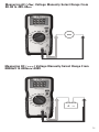
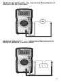
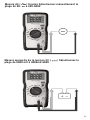
Measuring DC ( ) Voltage Manually Select Range From
0000mV to 4000mV-600V
Measuring AC ( ) Voltage Manually Select Range From
00.00 to 40V-600V
14

Measuring DC ( ) Voltage Manually Select Range From
0000mV to 4000mV-600V
15
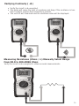
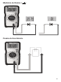
Verifying Continuity ( )
• Verify the circuit is de-energized.
• The meter will sense the level of resistance and beep if the resistance is less
than 10 Ω’s to confirm that continuity is present.
• The red LED will illuminate and the resistance value will be displayed.
Verify the circuit is de-energized to obtain accurate measurements.
Measuring Resistance (Ohms / Ω) Manually Select Range
From 00.0 to 400-4MEG Ohms

16
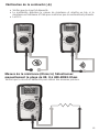
Measuring Diodes ( )
Testing a Battery

17
Measuring Diodes ( )
Testing a Battery
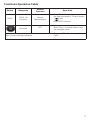
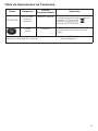
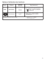
Button Response
Default
Function
Operation
HOLD
HOLD: All
Functions
Normal
Measurement
Short Press: Circularly enter or exit
the data hold mode, LCD will display
“ ” after
enter HOLD function.
Backlight
OFF
Short Press: Circularly enter or exit
the backlight mode
Non-Contact Voltage Indication
Displays “EF” – Electromagnetic
Field
Functions Operation Table

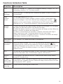
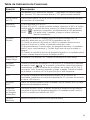
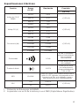
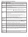
Functions Indication Table
Function Description
LCD One LCD. Displays a “-” symbol for all negative readings, displays “AC” for
alternating current or “DC” for direct current.
LCD
Backlight
White backlight. The backlight will automatically power off after 5 minutes
of inactivated
High
Voltage
Alarm
1) Only applicable to ACV / DCV
2) For ACV and DCV, when voltages in excess of 30V is measured or the
measured voltage is over limit, then the high voltage alarm symbol “ .”
appears on the screen display, simultaneously the LED remains RED and
beeping lasts for 1 second then becomes silent during measurement.
Regular
Prompt
1) When turning the dial switch to any setting position except OFF, the buzzer
will beep one time and the NCV LED flashes one time.
2) When the button selection is valid, the buzzer will beep one time; When the
button is invalid, the buzzer will beep twice.
3) About 1 minute before the automatic shutdown, the buzzer will beep 5
times continuously, and 1 long beep before the unit shuts down.
4) When the automatic shutdown function is canceled, the buzzer will beep 5
times when it reaches the APO time setting.
Over Range
Indication
LCD displays “OL” when over range is encountered.
Low Battery
Indication
When the battery voltage < 3.6 ±0.2V, the low battery indication ‘ ‘ is
displayed on the screen and the meter will still work normally. When the
battery voltage drops to less than 3.1 ±0.2V, “bAtt” is displayed for 5 seconds
then shuts off. When the battery voltage is less than 2.3V, accuracy is no
longer assured.
APO The unit will be automatically power off after 30 minutes of inactivity and
enter the low-power state. Current draw is approx. ≤50 micro A.
Restore
APO
All the buttons can wake up the unit, rotate the dial switch to any setting
except OFF to wake it up.
Disable
Auto Power
Off Function
Pressing the “HOLD” key while turning on the unit on at the same time, will
cancel the auto shutdown function. Buzzer will beep 5 times and the LCD will
not display the “APO” symbol.
Mechanical
Housing
Single Injection Molding with rubber boot.
18

Function Description
LCD One LCD. Displays a “-” symbol for all negative readings, displays “AC” for
alternating current or “DC” for direct current.
LCD
Backlight
White backlight. The backlight will automatically power off after 5 minutes
of inactivated
High
Voltage
Alarm
1) Only applicable to ACV / DCV
2) For ACV and DCV, when voltages in excess of 30V is measured or the
measured voltage is over limit, then the high voltage alarm symbol “ .”
appears on the screen display, simultaneously the LED remains RED and
beeping lasts for 1 second then becomes silent during measurement.
Regular
Prompt
1) When turning the dial switch to any setting position except OFF, the buzzer
will beep one time and the NCV LED flashes one time.
2) When the button selection is valid, the buzzer will beep one time; When the
button is invalid, the buzzer will beep twice.
3) About 1 minute before the automatic shutdown, the buzzer will beep 5
times continuously, and 1 long beep before the unit shuts down.
4) When the automatic shutdown function is canceled, the buzzer will beep 5
times when it reaches the APO time setting.
Over Range
Indication
LCD displays “OL” when over range is encountered.
Low Battery
Indication
When the battery voltage < 3.6 ±0.2V, the low battery indication ‘ ‘ is
displayed on the screen and the meter will still work normally. When the
battery voltage drops to less than 3.1 ±0.2V, “bAtt” is displayed for 5 seconds
then shuts off. When the battery voltage is less than 2.3V, accuracy is no
longer assured.
APO The unit will be automatically power off after 30 minutes of inactivity and
enter the low-power state. Current draw is approx. ≤50 micro A.
Restore
APO
All the buttons can wake up the unit, rotate the dial switch to any setting
except OFF to wake it up.
Disable
Auto Power
Off Function
Pressing the “HOLD” key while turning on the unit on at the same time, will
cancel the auto shutdown function. Buzzer will beep 5 times and the LCD will
not display the “APO” symbol.
Mechanical
Housing
Single Injection Molding with rubber boot.
19
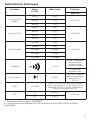
Electrical Specifications
Function Range
61-327
Resolution Accuracy
±(a%+b)
AC Voltage (V)
ARMS
40.00V 0.01V
±(1.3%+5)400.0V 0.1V
600.0V 1.0V
DC Voltage (V)
4000mV 1mV
±(1.3%+5)
40.00V 0.01V
400.0V 0.1V
600.0V 1.0V
Resistance (Ω)
400.0Ω 0.1Ω
±(1.5%+5)
4000Ω 1Ω
40.00kΩ 0.01kΩ
400.0kΩ 0.1kΩ
4.000MΩ 0.001MΩ
Continuity 0.1 Ω
≤10Ω : Buzzer beeps
and red indicator
LED illuminates
continuously
≥70Ω : No buzzer
beep
Diode test 0.001V
Silicon PN joint
with forward voltage
about 0.5V to 0.8V
NCV 40-600V
≥40V/(50~60Hz), with direct wire contact,
red indicator LED flashes at a frequency of
3Hz , and the buzzer beeps at a frequency of
3Hz simultaneously
BAT
1.5V
0.001V
±(1.3%+5)
9V
0.01V
1. Overload Protection: 600VRMS
2. Accuracy a is % of reading and b is LSD (Least Significant Digit).

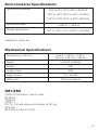
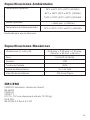
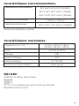
Environmental Specifications
Operating Temperature:
32ºF to 86ºF (0ºC to 30ºC) (80%RH)
86ºF to 140ºF (30ºC to 40ºC) (75%RH)
104ºF to 122ºF (40ºC to 50ºC) (45%RH)
Operating Altitude:
< 6500 ft (< 2000 m)
Storage Temperature:
14ºF to 140ºF (-10ºC to 60ºC) (<80%RH)
Mechanical Specifications
Dimensions (L x W x H) 6.54 in. x 3.23 in. x 1.89 in.
(166 mm. x 82 mm. x 48 mm.)
Weight 0.62 LBS (0.28 KG)
Display: LCD
Display Count 4000
Power Source: 3 x 1.5V AAA
Battery Life: 100 Hours Typical
EMC/EMI
20
CISPR 22 3rd Edition. Class B Limits.
EN 55032
CISPR 32
CISPR 11
FCC 15. 107 with reference to Section 15.109 (g).
ICES-003
EN 61326-2-2 Sec 6.4.2.101
Intended for indoor use
La page est en cours de chargement...
La page est en cours de chargement...
La page est en cours de chargement...
La page est en cours de chargement...
La page est en cours de chargement...
La page est en cours de chargement...
La page est en cours de chargement...
La page est en cours de chargement...
La page est en cours de chargement...
La page est en cours de chargement...
La page est en cours de chargement...
La page est en cours de chargement...
La page est en cours de chargement...
La page est en cours de chargement...
La page est en cours de chargement...
La page est en cours de chargement...
La page est en cours de chargement...
La page est en cours de chargement...
La page est en cours de chargement...
La page est en cours de chargement...
La page est en cours de chargement...
La page est en cours de chargement...
La page est en cours de chargement...
La page est en cours de chargement...
La page est en cours de chargement...
La page est en cours de chargement...
La page est en cours de chargement...
La page est en cours de chargement...
La page est en cours de chargement...
La page est en cours de chargement...
La page est en cours de chargement...
La page est en cours de chargement...
La page est en cours de chargement...
La page est en cours de chargement...
La page est en cours de chargement...
La page est en cours de chargement...
La page est en cours de chargement...
La page est en cours de chargement...
La page est en cours de chargement...
La page est en cours de chargement...
La page est en cours de chargement...
La page est en cours de chargement...
La page est en cours de chargement...
La page est en cours de chargement...
La page est en cours de chargement...
La page est en cours de chargement...
La page est en cours de chargement...
La page est en cours de chargement...
La page est en cours de chargement...
La page est en cours de chargement...
La page est en cours de chargement...
La page est en cours de chargement...
-
 1
1
-
 2
2
-
 3
3
-
 4
4
-
 5
5
-
 6
6
-
 7
7
-
 8
8
-
 9
9
-
 10
10
-
 11
11
-
 12
12
-
 13
13
-
 14
14
-
 15
15
-
 16
16
-
 17
17
-
 18
18
-
 19
19
-
 20
20
-
 21
21
-
 22
22
-
 23
23
-
 24
24
-
 25
25
-
 26
26
-
 27
27
-
 28
28
-
 29
29
-
 30
30
-
 31
31
-
 32
32
-
 33
33
-
 34
34
-
 35
35
-
 36
36
-
 37
37
-
 38
38
-
 39
39
-
 40
40
-
 41
41
-
 42
42
-
 43
43
-
 44
44
-
 45
45
-
 46
46
-
 47
47
-
 48
48
-
 49
49
-
 50
50
-
 51
51
-
 52
52
-
 53
53
-
 54
54
-
 55
55
-
 56
56
-
 57
57
-
 58
58
-
 59
59
-
 60
60
-
 61
61
-
 62
62
-
 63
63
-
 64
64
-
 65
65
-
 66
66
-
 67
67
-
 68
68
-
 69
69
-
 70
70
-
 71
71
-
 72
72


Ideal 61-327 Manuel utilisateur
- Catégorie
- Mesure, test
- Taper
- Manuel utilisateur
dans d''autres langues
- English: Ideal 61-327 User manual
- español: Ideal 61-327 Manual de usuario
Documents connexes
-
Ideal 61-405 Manuel utilisateur
-
Ideal 61-337 Manuel utilisateur
-
-
-
-
Ideal 61-657 Manuel utilisateur
-
-
-
-
Autres documents
-
Ega Master 51719 Le manuel du propriétaire
-
 LEXMAN LX-M-2000 Mode d'emploi
-
LEXMAN 3151700 Mode d'emploi
-
Klein Tools CL120 Manuel utilisateur
-
Klein Tools CL220 Manuel utilisateur
-
Amprobe VPC-30 Manuel utilisateur
-
UEi CLM100 Fiche technique
-
Innova 3430 Le manuel du propriétaire
-
Extech Instruments 445815 Manuel utilisateur
-
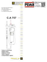 Chauvin-Arnoux C.A 757 Manuel utilisateur

