
Instrucciones en español adentro / Instructions en français à l’intérieur
61-657 Dual Range
12 to 1000V NCVT with Flashlight
61-647 Single Range
50 to 1000V NCVT
Operation and Safety Manual
IDEAL
®
Test and Measurement

Notes

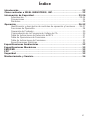
Table of Contents
3
Introduction .......................................................................4
Contacting IDEAL INDUSTRIES, INC ..........................................4
Safety Information ...............................................................5
Warnings ................................................................................................... 5-6
Cautions ........................................................................................................ 6
Symbols ........................................................................................................7
Operation......................................................................8-14
Identification and description of operating controls and functions .......... 8-9
Operating Features ......................................................................................10
Tester Operation ..........................................................................................11
Checking for The Presence of AC Voltage ...................................................12
NCV Sensing Indications Table ...................................................................13
Functions Operation Table ...........................................................................13
Function Indication Table ............................................................................14
Electrical Specifications ..............................................................................14
Environmental Specifications ................................................ 14
Mechanical Specifications ................................................... 15
EMC / EMI ....................................................................... 15
FCC ............................................................................ 15
Safety ............................................................................ 15
Maintenance and Service .................................................... 16

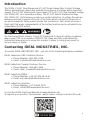
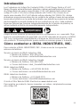
Introduction
The IDEAL 61-657 Dual Range and 61-647 Single Range Non-Contact Voltage
Testers automatically detect and indicate the presence of voltage within specified
ranges. The 61-657 detects both low voltage (12 to 50 V AC) and standard voltage
(50-1000V AC) via a selectable setting. The 61-647 detects standard voltage
(50-1000V AC). Both testers provide non-contact detection of voltage through an
antenna enclosed in plastic at the tip of the tester which senses the presence of
the electromagnetic field present around live conductors. Each tester also has a
flash light that works independently of the testing function and is activated by an
independent On/Off button.
Contacting IDEAL INDUSTRIES, INC.
To contact IDEAL INDUSTRIES, INC., call one of the following telephone numbers:
IDEAL Industries USA Customer Service
• Phone Number: 800-435-0705
• Email: [email protected]
IDEAL Industries Canada Customer Service
• Phone Number: 905-683-3400
• Email: [email protected]
IDEAL Industries EMEA
• Phone Number: +44 (0)1925 444 446
• Email: eur[email protected]
IDEAL Industries Australia
• Phone Number: +61 3 9562 0175
• Email: [email protected]
Or visit the IDEAL Electrical Website at www.idealind.com
To register your product, find manuals, watch videos, simply scan this QR code.
4
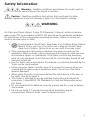
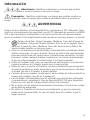
Arc Flash and Shock Hazard, Proper PPE Required. Follow all safety procedures,
wear proper PPE in accordance to NFPA 70E. Read and fully understand the
instruction manual prior to using this product. Failure to comply can result in
serious injury or death.

To contact IDEAL INDUSTRIES, INC., call one of the following telephone numbers:
IDEAL Industries USA Customer Service
• Phone Number: 800-435-0705
• Email: [email protected]
IDEAL Industries Canada Customer Service
• Phone Number: 905-683-3400
• Email: [email protected]
IDEAL Industries EMEA
• Phone Number: +44 (0)1925 444 446
• Email: eur[email protected]
IDEAL Industries Australia
• Phone Number: +61 3 9562 0175
• Email: [email protected]
Or visit the IDEAL Electrical Website at www.idealind.com
To register your product, find manuals, watch videos, simply scan this QR code.
Warning - Identifies conditions and actions that could result in
possible death or serious injury if the hazard is realized.
Caution - Identifies conditions and actions that could result in tester
damage, equipment under test damage or data loss if the hazard is realized.
WARNING
Safety Information
Arc Flash and Shock Hazard, Proper PPE Required. Follow all safety procedures,
wear proper PPE in accordance to NFPA 70E and follow the guidelines below and
the instructions in this manual when operating the tester. Failure to comply can
result in serious injury or death.
• Choking Hazard, Small Parts. Keep Away from Children Sharp Objects
Hazard, This is not a toy. It is not for use or play by children. Keep
Away from Children. Failure to do so can result in serious injury.
• Only experienced or technically competent consumers should use this
equipment. When in doubt, call an experienced electrician to make any and
all necessary repairs or installations. At all times, perform any necessary
work on a de-energized circuit that has had its circuit breaker turned off and
has been locked out.
• Use the Tester only as specified in this manual or protection provided by the
Tester can be compromised.
• Before using the Tester, visually inspect it to ensure the case or tip are not
cracked and the battery cap is securely in place. Do not use if the Tester
appears damaged.
• When using the tester, keep fingers behind the tactile barrier at the base of
the tester. (see #6 on page 9)
• This Tester is intended for use by qualified electricians and competent
consumers. Follow NFPA 70E Standards for Electrical Safety when using
this Tester.
• Do not use without the batteries correctly in place and the screw on battery
cap secured.
• Do not use Tester if it operates incorrectly as protection may be
compromised. When in doubt, have the Tester serviced.
5

• Have the Tester serviced only by qualified service personnel.
• Do not use the Tester around explosive gas, dust, or vapor, or during electrical
storms, or in wet environments.
• Do not apply more than the rated voltage, as marked on the Tester. Observe
CAT Rating of Tester when in use.
• To avoid false readings that can lead to electrical shock and injury, replace the
batteries as soon as the low battery indication appears.
• Voltages exceeding 30VAC or 60VDC pose a shock hazard so use caution.
• Do not work alone so that assistance can be rendered in an emergency.
• Use extreme caution when working around bare conductors or bus bars.
Contact with the conductor could result in electric shock.
• Adhere to local and national safety codes. Individual protective equipment
must be used to prevent shock and arc blast injury where hazardous live
conductors are exposed.
• These are IP67 dust & water resistant. Following any contact with water,
thoroughly dry prior to subsequent use.
• Cancer and Reproductive Harm - www.P65Warnings.ca.gov
6
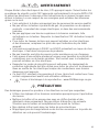
CAUTION
WARNING
Arc Flash and Shock Hazard, Proper PPE Required. Follow all safety procedures,
wear proper PPE in accordance to NFPA 70E and follow the guidelines below and
the instructions in this manual when operating the tester. Failure to comply can
result in serious injury or death.
Tester damage can occur if the following guidelines are not adhered to.
• Use the proper settings and voltage ratings for the measurement application.
• Clean the case and accessories with a damp cloth and mild detergents only.
Do not use abrasives or solvents. Make sure the tester is completely dry
before use.
• Not intended for insertion into electrical outlet slots.
• Do not apply excessive side or torsional loading to the sensing tip as
damage may occur.

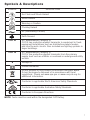
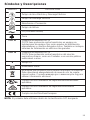
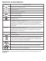
SYMBOL DESCRIPTION
Arc Flash and Shock Hazard
Shock Hazard
Warning or Caution
Choking Hazard
AC (Alternating Current)
Earth Ground
CAT III
IEC Measurement Category III
CAT III has protection against transients in equipment in fixed-
equipment installations such as distribution panels feeders,
and short branch circuits. Also included are lighting systems in
larger buildings.
CAT IV
IEC Measurement Category IV
CAT IV has protection against transients from the primary
supply level such as a Meter or overhead or underground utility
service.
V
Voltage AC
Double Insulation
Do not dispose of this product as unsorted municipal waste.
It must be properly disposed of in accordance with local
regulations. Please see www.epa.gov or www.erecycle.org for
additional information.
Conforms to applicable North American Safety Standards
Conforms to applicable Australian Safety Standards
Conforms to European Directives
Symbols & Descriptions
NOTE: Tester must be used within the designated CAT Rating.
7

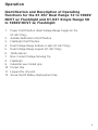
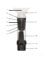
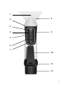
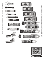
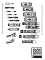
Identification and Description of Operating
Functions for the 61-657 Dual Range 12 to 1000V
NCVT w/ Flashlight and 61-647 Single Range 50
to 1000V NCVT w/ Flashlight:
1. Power On/Off button (Dual Voltage Range Toggle for the
61-657 Only)
2. Audible Notification On/Off button
3. Flashlight On/Off button
4. Dual Voltage Range Indicator Light (61-657 Only)
5. Dual Voltage Range Legend (61-657 Only)
6. Tactile Barrier
7. Non-Contact Voltage Sensing Tip
8. Flashlight
9. Industrial over-folded grip
10. Pocket Clip
11. Lanyard Tie off point
12. Screw On/Off Battery Replacement Cap
8
Operation

9
5
1
4
9
3
6
7
8
10
2
11
12

10
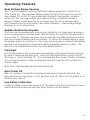
Operating Features
Dual Voltage Range Sensing
The 61-657 is capable of sensing 2 different voltage ranges 50 to 1000V AC or
12 to 1000V AC. The low range setting allows the tester to be used to sense the
low voltages (12 to 50V AC) associated with doorbells, thermostats, irrigation
wiring, etc. The low range setting also allows sensing of standard voltage in
tamper-resistant outlets when the tip is located near the Hot receptacle and/or
Hot Connection point on the outlet. (See Tester Operation – Dual Voltage Range
Sensing, for more information)
Audible Notification Disable
The tester can be operated with a visual only indication of voltage when working in
noise sensitive/noise restricted areas. With the tester On, press the Speaker button
for less than 1s. The tester will beep once to indicate the audible warning is muted
and only a visual indication will be provided. To restore the audible warning, press
the speaker button for less than 1s. The tester will beep twice to indicate the audible
warning is active and both a visual and audible indication will be provided. The
tester is set to Audible Notification On as the default setting.
Flashlight
An LED Flashlight in the tip operates independently of the tester functions and can
be used to illuminate the work area. Press the Flashlight Button to turn it On/Off.
The tester is set to Flashlight Off. The Flashlight will Auto Power Off after 5 minutes
of no voltage detection. Further voltage detection will reset the APO function to 5
minutes again.
Note: Use of the flashlight will decrease battery life.
Auto Power Off
After 10 minutes of inactivity (no button pressed and no signals detected), the
tester will emit one long beep (~0.5s) and then shut off. Note: if the flashlight is on,
it will be also shut off.
Low Battery Indication
If battery voltage is less than around 2.4V, the green led in the tip will flash 3 times
and the buzzer will send out one long beep, then turn off the device.

11
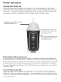
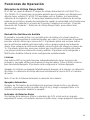
Tester Operation
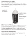
Turning The Tester On
Press the Power On/Off button for less than 1s to turn the tester On. The tester
will beep twice, and will light a steady Green LED in the tip of the tester to indicate
Power On. The High Voltage Sensing Mode will be activated (Default Range) and
indicated by lighting a steady Red Dual Voltage Range Indicator Light.
Dual Voltage Range Sensing
Short presses on the power button toggles the voltage sensing range between 50
to 1000V AC and 12 to 1000V AC. The tester defaults to the High Voltage Sensing
Mode (50 to 1000V AC) when the unit is turned on and is indicated by a steady Red
Indicator Light. Pressing the Power button for less that 1s will switch the tester to
the Low Voltage Sensing Mode (12 to 1000V AC) and is indicated by a steady Blue
Indicator Light.
Turning The Tester Off
Press the Power On/Off button for more than 1s (>2s for the 61-657) to turn the
tester Off. Listen for a long steady beep (~.5s) and watch for LED in the tip to turn
off and for the Range Indicator Light to turn Off. The tester is now deactivated and
is not operational.
Steady Green LED in the tip
indicates power-on
Red light indicates High
Voltage Range Sensing
(50-1000 V AC)
Blue Light indicates Low
Voltage Range Sensing
(12-1000 V AC)

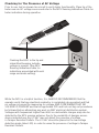
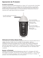
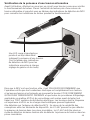
Checking for The Presence of AC Voltage
Prior to use, test on known live circuit to verify tester functionality. Place tip of the
tester near an AC voltage source and refer to the NCV Sensing Indications Table for
tester indication during operation.
While the NCV is a helpful function, it is ALWAYS RECOMMENDED that the
operator verify that any electrical conductor is completely de-energized and that
no voltage is present by measuring for voltage AND CONFIRMING THAT NO
VOLTAGE IS PRESENT and that all applicable PPE and lock out tag out procedures
be followed before attempting any work on ANY electrical distribution system.
Voltages with frequencies higher than 60Hz or electrostatic charges may also be
detected by the NCV sensing antenna. Due to the variability of designs across
device manufactures the 61-647 may not detect the presence of voltage
in Tamper Resistant Outlets. The 61-657 should be placed in the low voltage
detection mode (blue LED) in order to sense the presence of voltage in Tamper
Resistant Outlets.
Flashing Red LED in the tip and
intermittent beeping indicate
voltage is present. (See NCV
Sensing Indications table for
indications associated with each
range and mode setting)
12

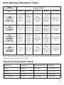
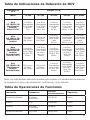
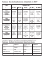
NCV
Indications
Ranges (V AC)
Mode
12-25V 26-34V 35-45V 46-54V 55-1000V
Low
(12-1000V AC)
(Audible
Notification)
(61-657 Only)
Red
Flashing
Light in
Tip and
beeps @
2Hz
Red
Flashing
Light in
Tip and
beeps
from 2Hz
to 4Hz
Red
Flashing
Light in Tip
and beeps
@ 4Hz
Red
Flashing
Light in Tip
and beeps
from 4Hz
to 12 Hz
Red Flashing
Light in Tip
and beeps
@ 12Hz
High
(50-1000V AC)
(Audible
Notification)
No Light
in Tip, No
beeps
No Light
in Tip, No
beeps
Red
Flashing
Light in Tip
and beeps
@ 2Hz
Red
Flashing
Light in Tip
and beeps
from 2Hz
to 12 Hz
Red Flashing
Light in Tip
and beeps
@ 12Hz
Low
(12-1000V AC)
(Audible
Notification
Disabled)
(61-657 Only)
Red
Flashing
Light in
Tip @
2Hz, No
beeps
Red
Flashing
Light in
Tip from
2Hz to
4Hz, No
beeps
Red
Flashing
Light in Tip
@ 4Hz, No
beeps
Red
Flashing
Light in Tip
from 4Hz
to 12Hz,
No beeps
Red Flashing
Light in Tip
@ 12Hz, No
beeps
High
(50-1000V AC)
(Audible
Notification
Disabled)
No Light
in Tip, No
beeps
No Light
in Tip, No
beeps
Red
Flashing
Light in Tip
@ 2Hz, No
beeps
Red
Flashing
Light in Tip
from 2Hz
to 12Hz,
No beeps
Red Flashing
Light in Tip
@ 12Hz, No
beeps
Indication Response Default Function Operation
On Off Meter On RED LED Push Button
Audible Beeps On Push Button
Flashlight Flashlight On Off Push Button
Sensing Range Red LED High Range Push Button
Functions Operation Table
13
NCV Sensing Indications Table
Note: Indications above may be subject to variability caused by humidity, insulation
thickness, distance, and other factors.

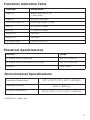
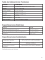
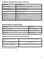
Functions Indication Table
Function Description
Power On Steady Green light in Tip,
2 Short Beeps
Power Off No Light, Long Beep
Tester Auto Power Off Green Light Flashes, 1 Beep
Red LED 50-1000V AC Range
Blue LED 12-1000V AC Range
Audible OFF One Beep
Audible ON Two Beeps
Flashlight Button Flashlight On or Off
Electrical Specifications
Function Range
AC Voltage Sensing High Mode 50V AC to 1000V AC
AC Voltage Sensing Low Mode (61-657 Only) 12V AC to 1000V AC
Frequency 50Hz or 60Hz
14
Environmental Specifications
Operating Temperature: 32ºF to 104ºF (0ºC to 40ºC) (<80%RH)
Operating Altitude:
6500 ft (2000 m)
Storage Temperature:
14ºF to 122ºF (-10ºC to 50ºC) (<80%RH)
Intended for indoor use.

Functions Indication Table
Function Description
Power On Steady Green light in Tip,
2 Short Beeps
Power Off No Light, Long Beep
Tester Auto Power Off Green Light Flashes, 1 Beep
Red LED 50-1000V AC Range
Blue LED 12-1000V AC Range
Audible OFF One Beep
Audible ON Two Beeps
Flashlight Button Flashlight On or Off
Electrical Specifications
Function Range
AC Voltage Sensing High Mode 50V AC to 1000V AC
AC Voltage Sensing Low Mode (61-657 Only) 12V AC to 1000V AC
Frequency 50Hz or 60Hz
Environmental Specifications
Operating Temperature: 32ºF to 104ºF (0ºC to 40ºC) (<80%RH)
Operating Altitude:
6500 ft (2000 m)
Storage Temperature:
14ºF to 122ºF (-10ºC to 50ºC) (<80%RH)
15
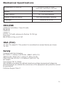
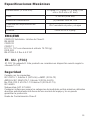
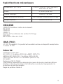
Mechanical Specifications
Dimensions: (L x W x H) 6.4 in. x 1.0 in. x 1.2 in.
(166 mm x 26.3 mm x 31 mm)
Weight: 0.16 LBS (0.08 KG)
Power Source: (2) 1.5V AAA Batteries
Ingress Protection Rating: IP67 dust and water resistant
Flashlight: >500LUX @ 4.0 in
EMC/EMI
CISPR 22 3rd Edition. Class B Limits.
EN 55032
CISPR 32
CISPR 11
FCC 15. 107 with reference to Section 15.109 (g).
ICES-003
EN 61326-2-2 Sec 6.4.2.101
USA (FCC)
47 CFR 15 subpart B. This product is considered an exempt device per clause
15.103.
Safety
Complies with the following:
IEC 61010-1, Edition 3 (2010-06) +AMD1 (2016-12)
ANSI/UL/IEC EN 61010-1, Edition 3 (2016-04-29)
CSA-C22.2 No. 61010-1-12 Edition 3 (2019-07-19)
IEC 60529
Overvoltage CAT IV 1000V.
Any voltages exceeding the defined maximum voltage measurement categories
described above are outside the normal use of the equipment and protection cannot
be guaranteed.
Pollution Degree Class 2

16
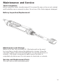
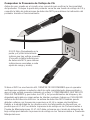
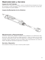
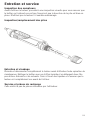
Tester Inspection
Before using the Tester, visually inspect it to ensure the case or tip are not cracked
and the battery cap is securely in place. Do not use if the Tester appears damaged.
Battery Inspection/Replacement
Maintenance and Storage
When not in use, turn the meter off. If the tester will not be used
for more than a month remove the batteries for storage. Clean the
case with a damp cloth and mild detergent. Do not use abrasives or
solvents. If the meter is exposed to water ensure the tester is
completely dry before use. Do not expose to chemicals or solvents.
Service and Replacement Parts
This unit has no user-serviceable parts.
Maintenance and Service

Maintenance and Service
In order to preserve, protect and improve the quality of the environment, protect
human health and utilize natural resources prudently and rationally, the user should
return unserviceable product to relevant facilities in accordance with statutory
regulations. The crossed-out wheeled bin indicates the product needs to be
disposed separately and not as municipal waste.
Do not dispose of this product as unsorted municipal waste. It must be properly
disposed of in accordance with local regulations. Please see www.epa.gov or
www.erecycle.org for additional information.
There are no batteries in this product.
Disposal of Waste, Electrical & Electronic Equipment
Disposal of Used Batteries/Accumulators
TWO YEAR LIMITED WARRANTY
This tester is warranted to the original purchaser against defects in material and
workmanship for a period of two (2) years from date of purchase. With proof of
purchase from an authorized IDEAL distributor, a defective tester will be repaired or
replaced with the same product or a functionally equivalent product, at the option
of IDEAL INDUSTRIES, INC. during the warranty period, subject to verification
of the defect or malfunction. Warranty does not cover consumables such as
fuses, batteries, and excludes defects caused by leakage from batteries, abuse,
mishandling, dropping, ordinary wear and tear, misuse, neglect, unauthorized
repair, improper use, alterations, accidents or any causes beyond IDEAL’s
reasonable control. Consequential or incidental damages are not recoverable under
this warranty. Some states do not allow the exclusion or limitation of incidental or
consequential damages, so the above limitation or exclusion may not apply to you.
This LIMITED WARRANTY gives you specific legal rights, which vary from state to
state. This warranty constitutes the sole and exclusive remedy of the purchaser and
the exclusive liability of IDEAL, and is in lieu of any and all other warranties, and
expressly disclaims all other warranties, implied, or statutory as to merchantability,
fitness for purpose sold, description, quality productiveness, or any other matter.
No agent, distributor or other supplier has the authority to modify or amend this
warranty or make other representations or warranties other than those contained
in this warranty without express written authorization from IDEAL. For warranty
service, call IDEAL customer service at 1-800-435-0705.
Made in China.
17

IDEAL INDUSTRIES, INC. Sycamore, IL 60178, U.S.A. 800-435-0705 www.Idealind.com ND 9110-1
Scan the barcode on the right to see the new IDEAL T&M Product Line

Instrucciones en español adentro / Instructions en français à l’intérieur
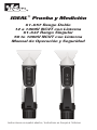
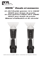
61-657 Rango Doble
12 a 1000V NCVT con Linterna
61-647 Rango Singular
50 to 1000V NCVT con Linterna
Manual de Operación y Seguridad
IDEAL
®
Prueba y Medición

Notas
La page est en cours de chargement...
La page est en cours de chargement...
La page est en cours de chargement...
La page est en cours de chargement...
La page est en cours de chargement...
La page est en cours de chargement...
La page est en cours de chargement...
La page est en cours de chargement...
La page est en cours de chargement...
La page est en cours de chargement...
La page est en cours de chargement...
La page est en cours de chargement...
La page est en cours de chargement...
La page est en cours de chargement...
La page est en cours de chargement...
La page est en cours de chargement...
La page est en cours de chargement...
La page est en cours de chargement...
La page est en cours de chargement...
La page est en cours de chargement...
La page est en cours de chargement...
La page est en cours de chargement...
La page est en cours de chargement...
La page est en cours de chargement...
La page est en cours de chargement...
La page est en cours de chargement...
La page est en cours de chargement...
La page est en cours de chargement...
La page est en cours de chargement...
La page est en cours de chargement...
La page est en cours de chargement...
La page est en cours de chargement...
La page est en cours de chargement...
La page est en cours de chargement...
-
 1
1
-
 2
2
-
 3
3
-
 4
4
-
 5
5
-
 6
6
-
 7
7
-
 8
8
-
 9
9
-
 10
10
-
 11
11
-
 12
12
-
 13
13
-
 14
14
-
 15
15
-
 16
16
-
 17
17
-
 18
18
-
 19
19
-
 20
20
-
 21
21
-
 22
22
-
 23
23
-
 24
24
-
 25
25
-
 26
26
-
 27
27
-
 28
28
-
 29
29
-
 30
30
-
 31
31
-
 32
32
-
 33
33
-
 34
34
-
 35
35
-
 36
36
-
 37
37
-
 38
38
-
 39
39
-
 40
40
-
 41
41
-
 42
42
-
 43
43
-
 44
44
-
 45
45
-
 46
46
-
 47
47
-
 48
48
-
 49
49
-
 50
50
-
 51
51
-
 52
52
-
 53
53
-
 54
54


Ideal 61-657 Manuel utilisateur
- Taper
- Manuel utilisateur
- Ce manuel convient également à
dans d''autres langues
- English: Ideal 61-657 User manual
- español: Ideal 61-657 Manual de usuario
Documents connexes
-
Ideal Single Range 24-600V AC NCVT Manuel utilisateur
-
-
-
-
Ideal 61-337 Manuel utilisateur
-
-
Ideal VoltAware NCV Mode d'emploi
-
-
-
Autres documents
-
Klein Tools MPZ00027 Mode d'emploi
-
 UEi NCV3 Fiche technique
-
-
-
-
-
-
Ega Master 58516 Le manuel du propriétaire
-
Klein Tools M2O41408KIT Manuel utilisateur
-
