Garland 36ER33-88 Owner Instruction Manual
- Catégorie
- Cuisinières
- Taper
- Owner Instruction Manual

Part # 1382677 - 2/15
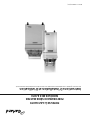
MASTER SERIES
HEAVY DUTY GAS FRYERS
MODELS M/MST35 & M/MST70
Installation, Operation and Maintenance Manual
This manual is updated as new information and models are released. Visit our website for the latest manual.

Part # 1382677 - 2/15
Page 2
IMPORTANT INFORMATION
WARNING:
This product contains chemicals known to the state of california to cause cancer and/or birth defects
or other reproductive harm. Installation and servicing of this product could expose you to airborne
particles of glass wool/ceramic fibers. Inhalation of airborne particles of glass wool/ceramic fibers
is known to the state of california to cause cancer. Operation of this product could expose you to
carbon monoxide if not adjusted properly. Inhalation of carbon monoxide is known to the state of
california to cause birth defects or other reproductive harm.
Keep appliance area free and clear of combustibles.
NOTE: Before leaving the factory, the fryer was tested with oil in the frypot; therefore, it is necessary to clean the frypot
before adding frying compound. Rinse the frypot with clean water, then put some fryer cleaner on a damp cloth, full
strength, and wipe the entire frypot clean. Rinse it thoroughly and wipe dry. The fryer is now ready for use. If the fryer
does not have a stainless steel frypot and is not to be used immediately after cleaning, coat the entire frypot surface
with shortening or cooking oil to prevent rusting.
Users are cautioned that maintenance and repairs must be performed by a Garland authorized service agent
using genuine Garland replacement parts. Garland will have no obligation with respect to any product that has been
improperly installed, adjusted, operated or not maintained in accordance with national and local codes or installation
instructions provided with the product, or any product that has its serial number defaced, obliterated or removed,
or which has been modified or repaired using unauthorized parts or by unauthorized service agents.
For a list of authorized service agents, please refer to the Garland web site at http://www.garland-group.com.
The information contained herein, (including design and parts specifications), may be superseded and is subject
to change without notice.
FOR YOUR SAFETY:
DO NOT STORE OR USE GASOLINE
OR OTHER FLAMMABLE VAPORS OR
LIQUIDS IN THE VICINITY OF
THIS OR ANY OTHER
APPLIANCE
WARNING:
IMPROPER INSTALLATION, ADJUSTMENT,
ALTERATION, SERVICE OR MAINTENANCE
CAN CAUSE PROPERTY DAMAGE, INJURY,
OR DEATH. READ THE INSTALLATION,
OPERATING AND MAINTENANCE
INSTRUCTIONS THOROUGHLY
BEFORE INSTALLING OR
SERVICING THIS EQUIPMENT
PLEASE READ ALL SECTIONS OF THIS MANUAL
AND RETAIN FOR FUTURE REFERENCE.
THIS PRODUCT HAS BEEN CERTIFIED AS
COMMERCIAL COOKING EQUIPMENT AND
MUST BE INSTALLED BY PROFESSIONAL
PERSONNEL AS SPECIFIED.
IN THE COMMONWEALTH OF MASSACHUSETTS
THIS PRODUCT MUST BE INSTALLED BY A
LICENSED PLUMBER OR GAS FITTER. APPROVAL
NUMBER: G-1-07-05-28
For Your Safety:
Post in a prominent location, instructions to be
followed in the event the user smells gas. This
information shall be obtained by consulting
your local gas supplier.

Part # 1382677 - 2/15
Page 3
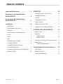
TABLE OF CONTENTS
Important Information . . . . . . . . . . . . . . . . . 2
Dimensions And Speci cations,
Model M/MST35 . . . . . . . . . . . . . . . . . . . . . . . 4
Dimensions And Speci cations,
Model M/MST70 . . . . . . . . . . . . . . . . . . . . . . . 5
Installation . . . . . . . . . . . . . . . . . . . . . . . . . . . . 6
Rating Plate . . . . . . . . . . . . . . . . . . . . . . . . . . . . . . . . . . 6
Pre-Installation Instructions . . . . . . . . . . . . . . . . . . 6
Clearances . . . . . . . . . . . . . . . . . . . . . . . . . . . . . . . . . . 7
Gas Connections and Piping Sizing . . . . . . . . . . . 7
Frypot . . . . . . . . . . . . . . . . . . . . . . . . . . . . . . . . . . . . . . . 7
Casters . . . . . . . . . . . . . . . . . . . . . . . . . . . . . . . . . . . . . . 7
Legs . . . . . . . . . . . . . . . . . . . . . . . . . . . . . . . . . . . . . . . . . 7
Ventilation and Air Supply . . . . . . . . . . . . . . . . . . . . 8
Assembly Of Battery . . . . . . . . . . . . . . . . . . . . . . . . . 8
Assembly Instructions M-Series
Low Pro le Backguard . . . . . . . . . . . . . . . . . . . . . . . 9
Assembly Instructions M-Series Backguard . . . . 9
Radiation Shield . . . . . . . . . . . . . . . . . . . . . . . . . . . . 10
OPERATION . . . . . . . . . . . . . . . . . . . . . . . . . . 10
Using the Fryer for the First Time . . . . . . . . . . . .10
Lighting Instructions . . . . . . . . . . . . . . . . . . . . . . . . 11
Stand By . . . . . . . . . . . . . . . . . . . . . . . . . . . . . . . . . . . . 11
Complete Shut Down . . . . . . . . . . . . . . . . . . . . . . . 11
Safety Concerns . . . . . . . . . . . . . . . . . . . . . . . . . . . . 11
Optimum Operation Tips . . . . . . . . . . . . . . . . . . . . 11
Suggestions for Quality Fried Food . . . . . . . . . . 12
CLEANING AND MAINTENANCE . . . . . . . . 13
Routine Care . . . . . . . . . . . . . . . . . . . . . . . . . . . . . . . . 13
Cleaning . . . . . . . . . . . . . . . . . . . . . . . . . . . . . . . . . . . . 13
Painted Finishes . . . . . . . . . . . . . . . . . . . . . . . . . 13
Stainless Steel . . . . . . . . . . . . . . . . . . . . . . . . . . . 13
Draining and Filtering Of Fryer Compound . . . 13
Maintenance . . . . . . . . . . . . . . . . . . . . . . . . . . . . . . . 14
Preventive Maintenance . . . . . . . . . . . . . . . . . 14
Trouble Shooting And Adjustments . . . . 15
Adjustments . . . . . . . . . . . . . . . . . . . . . . . . . . . . . . . . 15
Trouble Shooting . . . . . . . . . . . . . . . . . . . . . . . . . . . 15
Thermostat Calibration . . . . . . . . . . . . . . . . . . . . . 16

Part # 1382677 - 2/15
Page 4
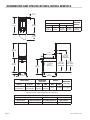
3-1/2"
[89mm]
34-3/8"
[873mm]
13-1/8"
[333mm]
37-7/8"
[962mm]
33-3/8"
[848mm]
30-1/4"
[768mm]
6"
[152mm]
1-1/4" N.P.T.
[32mm]
GAS INLET
63-3/4"
[1619mm]
With "DDBG"
46-3/4"
[1187mm]
With "BG"
40-1/4"
[1022mm]
With "LPBG"
BACKGUARD
BACKGUARD
BACKGUARD
31-1/2"
[800mm]
33-7/8"
[860mm]
17"
[432mm]
34"
[864mm]
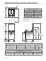
TOTAL INPUT
OPERATING
PRESSURE
ORIFICE
MANIFOLD
PIPE SIZE
Natural Propane NAT PRO NAT PRO
110,000 BTU/Hr
(32.23kW/Hr)
85,000 BTU/Hr
(24.91kW/Hr)
4.0" WC
(10mbar)
9.0" WC
(22mbar)
#51 1.05MM 1-1/4” N.P.T
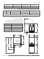
Gas input ratings shown here are for installations up to 2,000 feet (610mm) above sea level.
Input must be derated for high altitude installations.
FRYING CAPACITY (per hour)
FRENCH FRIES FISH BREADED CHICKEN
Raw to Done Blanched to Done 3oz. (84g), Battered Raw to Done
60lb. (27kg) 80lb. (36kg) 60lb. (27kg) 28lb. (13kg)
DIMENSIONS AND SPECIFICATIONS, MODEL M/MST35
CLEARANCES
SHIPPING
WEIGHT
INSTALLATION ENTRY
Sides Rear Crated Uncrated
6"
(152mm)
6"
(152mm)
29-1/4"
(746mm)
17-1/4"
(618mm)
220lb.
(100kg)

Part # 1382677 - 2/15
Page 5
3-1/2"
[89mm]
34-3/8"
[873mm]
37-7/8"
[962mm]
33-3/8"
[848mm]
30-3/8"
[772mm]
6"
[152mm]
1-1/4" N.P.T.
[32mm]
GAS INLET
63-3/4"
[1619mm]
W/"DDBG"
BACKGUARD
46-3/4"
[1187mm]
W/ "BG"
BACKGUARD
40-1/4"
[1022mm]
W/"LPBG"
BACKGUARD
31-1/2"
[800mm]
33-7/8"
[860mm]
34"
[864mm]
19-5/8"
[498mm]
24"
[610mm]
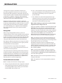
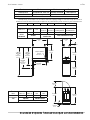
DIMENSIONS & SPECIFICATIONS
Width 24"(612mm)
Depth 38" (965mm
Height (w/ NSF Legs) 36-3/8" (924mm)
Height (w/o NSF Legs) 30-3/8" (772mm)
Input-BTU (Natural Gas) 125,000 (36.62 kW)
Shipping WT:(LB/KG) 225(120.5)
Gas input ratings shown here are for installations up to 2,000
feet (610mm) above sea level Input must be derated for high
altitude installations.
Gas manifold pipe size: 1-1/4” N.P.T.
INSTALLATION NOTES
Combustible Wall Clearances ¹ Entry Clearances
Manifold Operating
Pressure
Ori ce
Sides: 6" (152mm
Back: 6" (152mm)
Crated: 29-1/4" (997mm)
Uncrated: 17-1/4" (438mm)
Natural: 6" WC (15mbar)
Propane: 10" WC (25mbar)
NAT
#56
PRO
#66
¹NOTE: Installation clearance reductions are applicable only where local codes permits. NOTE: Data applies only to North America.
PRODUCTION CHART: Frying Capacities (per hour)
French Fries Fish Breaded Chicken
Raw to Finish
70 lb (32 kg)
Blanced to Finish
95 lb (43 kg)
3 oz Battered
100 lb (45 kg)
Raw to Done
28 lb (13 kg)
DIMENSIONS AND SPECIFICATIONS, MODEL M/MST70

Part # 1382677 - 2/15
Page 6
INSTALLATION
The importance of proper installation of commercial
gas cooking equipment cannot be over stressed. Proper
performance of the equipment is dependent, in great part,
on the compliance of the installation with the manufacturer’s
speci cations. In addition, compliance with the National
Fuel Gas code ANSI Z 223.1-1988/NFPA and/or Local code is
required to assure safe and e cient operation.
Appliances shall be installed in a location in which the
facilities for ventilation permit satisfactory combustion of gas
and proper venting. Appliances shall be located so as not to
interfere with proper circulation of air within the con ned
space. When buildings are so tight that normal in ltration
does not provide the necessary air, outside air shall be
introduced.
Rating Plate
When corresponding with the factory or your local
authorized factory service center regarding service problems
or replacement parts, be sure to refer to the particular unit
by the correct model number (including the pre x and su x
letters and numbers) and the warranty serial number. The
rating plate a xed to the unit contains this information.
We suggest installation, maintenance and repairs should be
performed by your local authorized service agency listed in
your information manual pamphlet.
In the event you have any questions concerning the
installation, use, care or service of the product, write or call
our Product Service Department.
This product must be installed by professional personnel as
speci ed. Garland/U.S. Range products are not approved or
authorized for home or residential use, but are intended for
commercial applications only. Garland / U.S. Range will not
provide service, warranty, maintenance or support of any
kind other than in commercial applications.
Pre-Installation Instructions
Before assembly and connection check gas supply.
A. The type of gas for which the unit is equipped is stamped
on the data plate located on inner door panel. Connect
a unit stamped “NAT” only to natural gas; connect those
stamped “PRO” only to propane gas.
B. If it is a new installation have the gas authorities check
meter size and piping to assure that the unit is supplied
with su cient amount of gas pressure required to
operate the UNIT.
C. If it is additional or replacement equipment have gas
authorities check pressure to make certain that existing
meter and piping will supply fuel to the unit with not
more than ½” water column pressure drop.
NOTE: When checking gas pressure be sure that all other
equipment on the same gas line is on.
A pressure regulator is supplied as standard equipment with
GARLAND Heavy Duty Gas Fryers and Restaurant Gas Series
Fryers. The pressure regulator is “built-in” to the fryer, (the
regulator is part of the combination safety valve). Installation
must conform with the National Fuel Gas code ANSI Z223.1-
1988 or latest edition NFPA No. 54-Latest Edition and
National Electrical code ANSI/NFPA 70-1990 or latest edition
and/or local code to assure safe and e cient operation.
NOTE: The appliance and its individual shut-o valve (not
supplied by manufacturer) must be disconnected from the
gas supply piping system during any pressure testing of that
system at pressures in excess of 1/2 PSIG
(3.45 KPa). The appliance must be isolated from the gas
supply piping system by closing its individual manual shut-
o (not supplied by manufacturer) during any testing of the
gas supply piping system at test pressures equal to or less
than 1/2 PSIG (3.45KPa).
NOTE: In Canada, the installation shall be in accordance
with CAN/CGA-B149.1 NATURAL GAS INSTALLATION CODE
or CAN/CGA-B149.2 PROPANE GAS INSTALLATION CODE and
local codes where applicable.
NOTE: Adequate clearance must be provided for servicing
and proper operation.
NOTE: This appliance is not recommended for residential
installation.

Part # 1382677 - 2/15
Page 7
Clearances
From Combustible material 6” (152mm) sides and rear. A
clearance of 0.0” to non combustible construction as sides
& rear is acceptable. The fryer is suitable for installation on
combustible oor.
Gas Connections and Piping Sizing
The size of the gas line is very important. If the line is too
small, the gas pressure at the burner manifold will be low.
This will cause slow recovery, delayed ignition, and pilot
outage. Refer to the Gas Line Sizing Chart in the nation Fuel
Codebook.
Before connecting new pipe to your GARLAND Fryer, the
pipe must be thoroughly blown out to depose of all foreign
particles. If these foreign particles get into the burner and
controls they will cause improper and sometimes dangerous
operation.
When using thread compound, use it sparingly and one on
male threads. Use compound that is impervious to the action
of Propane gases. Do not put any on the rst two threads.
This will prevent fouling the controls and clogging the pilot
and main burner ori ces.
Make sure that installer checks all plumbing with a soap
solution for leaks. DO NOT USE A FLAME, MATCHES,
CANDLES, or other ignition source in checking for leaks.
Frypot
Before leaving the factory, the fryer was tested, and the
thermostat was calibrated, with oil in the frypot; therefore,
it is necessary to clean the frypot before adding frying
compound. Rinse the frypot with clean water, then put some
fryer cleaner on a damp cloth, full strength, and wipe the
entire frypot clean. Rinse it thoroughly and wipe dry. The
fryer is now ready for use. If the fryer doe not have a stainless
steel frypot and is not to be used immediately after cleaning,
coat the entire frypot surface with shortening or cooking oil
to prevent rust.
Casters
A. The installation shall be made with a connector that
complies with the Standard for Connectors for Moveable
Gas Appliances, ANSI Z21.69/CSA 6.16, Addenda Z21.69B-
2006/CSA 6.16B-2006 (or latest edition), and a quick-
disconnect device that complies with the Standard for
Quick Disconnects for Use with Gas Fuel, ANSI Z21.41/
CSA 6.9, Addenda Z21.41A-2005/CSA 6.16A-2005 (or
latest edition).
B. The front casters of the unit are equipped with brakes
to limit the movement of the fryer without depending
on the connector and any quick disconnect device or its
associated piping to limit the appliance movement.
C. Please be aware, required restraint is attached to a
bracket on the fryer (connection point is located on the
left rear caster of the fryer), and if disconnection of the
restraint is necessary, be sure to reconnect the restraint
after the fryer has been returned to its originally installed
position.
NOTE: When installed, the fryer must be restrained to
prevent tipping in order to avoid the splashing of hot liquid.
The means of restraint may be the manner of installation,
such as connection to a battery of appliances. Or installing
the fryer in an alcove, or by separate means, such as
adequate ties.
Legs
Raise front of the unit and block. Do not lay unit on its back..
Position leg insert into leg retainer opening and tap up until
it seats at collar ange. Repeat at rear of unit making sure all
four legs are adjusted to same height. Legs can be adjusted
to overcome an uneven oor.
CAUTION: These types of GARLAND Fryers cannot be
installed on a masonry base or without proper clearance
from oor. Primary air is supplied to the ‘jet – type” burner
from the front and mainly from the bottom of the fryer. If
installed on a masonry base or directly on oor without
the use of the factory supplied 6” (152mm) legs or casters,
improper combustion will occur.
INSTALLATION Continued

Part # 1382677 - 2/15
Page 8
INSTALLATION Continued
Ventilation and Air Supply
One of the most important considerations is ventilation.
The fryer must be installed so that products of combustions
are removed e ciently, but so that the kitchen ventilation
system does not produce drafts that interfere with proper
burner operation. The fryer ue opening must NOT be placed
close to the intake of the exhaust fan.
The fryer must never have its ue extended in a chimney
fashion. This changes the combustion characteristics of the
fryer. This will cause the fryer to be slow to recover, frequently
cause delayed ignition, and sometimes cause pilot outage.
The ideal method of ventilating a fryer is the use of a
properly designed canopy which should extend six inches
(6”) (152mm)beyond all sides of the appliance and six feet
(6’) six inches (6”) (1981mm) from the oor.
Many operators do not realize that the nest ventilation
system will break down when it is not maintained properly.
The duct system, the hood, and the lter bank must be
cleaned on a regular basis and kept free of grease.
Adequate distances must be maintained from the ue outlet
of the fryer to the lower edge of the lter bank. Filters should
never be installed in the horizontal position. They should be
installed at an angle of 45 degrees, and a drip tray should be
located beneath the lowest edge of the lter. NFPA Standard
No.96 states that “A Minimum distance of 18” (457mm)
should be maintained between the ue outlet and the lower
edge of the grease lter.” We recommend that the MINIMUM
DISTANCE BE 24” (610mm) FROM THE FLUE OUTLET TO
THE BOTTOM EDGE OF THE FILTER WHEN THE APPLIANCE
CONSUMES MORE THAN 120,000 B.T.U. PER HOUR.
A strong exhaust fan will create a vacuum in the room, for an
exhaust system vent to work properly, replacement air must
enter the room in which the vent is located.
All gas burners and pilots need su cient air to operate and
large objects should not be placed in front of this fryer which
would obstruct the air ow through the front. A minimum of
24” (610mm) should be provided at the front of the unit for
servicing and proper operation. Air for combustion enters
the unit below the cabinet at the base. Do not place anything
around the base or under the fryer.
Assembly Of Battery
All heavy duty batteries equipment is aligned and tted at
the factory, from left to right and must be installed in this
order. There is a diagram provided with every heavy duty
battery. All 35M/MST Fryers and 70M/MST Fryers may be
installed to battery with other GARLAND 40 Series Ranges,
sharing common manifold connections.
A. All such units should be placed in their respective battery
position. Detach valve panels to prevent damage,
remove them from the area where the battery is being
assembled.
B. Level each unit (if a range, to the oven rack) by adjusting
the six inch (6”/152mm) legs, or where legs are not used,
adjust level with shims. Readjust legs, if required.
C. Connect units together by mating the unions at each
end of the manifold. (Adjoining units must have
matching unions, unless the union parts are of the
same speci cations, a leak proof connection cannot be
assured.) Hand tighten unions at this point.
D. The units should be fastened at the rear by inserting 5/16”
bolts through the holes provided at the rear of the burner
box sides. Install washer and nut and hand tighten. Be
sure of proper unit alignment in the battery before nal
tightening of these bolts or unions. Improper tightening
will cause “fanning” or “bowing” of batteried units.
The nal tightening of the union should be accomplished
by using a suitable spanner wrench. If such a wrench
is not available, the GARLAND union collar has special
ridges, and a cold chisel can be driven against these
ridges to properly seat and seal the union.
E. The manifold of this unit or the manifold of which is
a part of must be equipped with a certi ed pressure
regulator suitable for battery application and adjustable
for an outlet pressure at the manifold as speci ed on the
rating place

Part # 1382677 - 2/15
Page 9
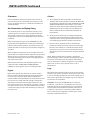
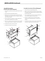
INSTALLATION Continued
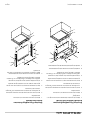
Assembly Instructions
M-Series Low Pro le Backguard
1. Remove ue cap #6 by removing six (6) [#10] sheet metal
screws.
2. Remove front panel #5 by lifting upward.
3. With back panel #4 still attached to the left #2 and right
#3 uprights, drop uprights into the rectangular cutouts at
the rear of the range #1.
4. Fasten uprights #2 and #3 to the range #1 with four (4)
5/16” -18 bolts and at washers #7 and #8.
5. If unit is in a battery lineup, fasten adjacent units together
at hole marked “X” with 1/4” -20 bolts, nuts, and washers.
6. Install front panel #5 previously remove.
7. Install ue cap #6 previously removed.
~
~
1
"X"
"X"
2
5
8
7
3
6
9
4
Assembly Instructions M-Series Backguard
1. Remove front panel #5 by lifting upward.
2. With back panel #4 still attached to the left #2 and right
#3 uprights, drop uprights into the rectangular cutouts at
the rear of the range.
3. Fasten uprights #2 and #3 to the range #1 with four (4)
5/16” -18 bolts and at washers #6 and #7.
4. If unit is in a battery line up, fasten adjacent units
together at hole marked “X” with 1/4” -20 bolts and
washers.
5. Install front panel #5 previously removed. Attach front
panel #5 to range #1 with sheet metal screws.
1
"X"
"X"
2
5
8
4
3
6
7

Part # 1382677 - 2/15
Page 10
Using the Fryer for the First Time
Before lighting the pilot, ll the frypot with frying compound.
Then light the pilot according to the instructions inside
the fryer compartment on the inner panel. If you are using
a cooking oil, you may now turn the main burner on by
turning the knob on the automatic gas valve. If you use a
hydrogenated (solid) frying compound, it is wise to melt it in
a stock pot on the range before putting it in the fryer. If this
is not done, pack the frypot with the compound and turn the
main burner on for a few seconds and turn it o for a few. See
the lighting and shut-down instructions for “How to turn on
the main burner once the pilot is lighted.”
Intervals of about three seconds on and ten seconds o are
about right. Keep doing this until the shortening is melted.
If any smoke is seen during this process, you are heating
too fast and scorching the shortening, thus cutting down
its useful life and possible damaging the frypot. Shortening
level must cover the thermostat bulbs when fryer is in
operation.
After turning the main burner on, set the thermostat at 325°
to check calibration of the thermostat. Let the burner cycle
at least four times and suspend a deep fat fryer thermometer
in the middle of the frypot about 3” deep. When the burner
just comes on after the fourth cycle, the reading on the
thermostat should agree with the thermostat setting. If not,
calibrate the thermostat according to the instructions in the
Cleaning and Maintenance Section of this manual.
OPERATION
INSTALLATION Continued
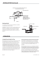
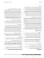
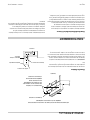
Radiation Shield
This radiation shield must be in place when fryer is installed
in other than re resistive locations.
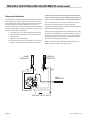
IMPORTANT: The ue riser must be installed within the back
guard. This rectangular riser ts over the collar of the ue
collector box inside the fryer. Place the ue riser upright
through opening in the back top and slide over collar. (See
Figure 2.).
FLUE RISER
BACK ALUMINIZED
SIDES AND FRONT
HEAT SHIELD
FIGURE 2
RADIATION SHIELD
REMOVE EXISTING
#10 SHEET METAL
SCREWS (2 REQ'D)
FROM HIGH SHELF OR
BACKGUARD TO INSTALL
RADIATION SHIELD
FIGURE 1
METHOD OF ATTACHING RADIATION SHIELD TO
BACKGUARD OR HIGH SHELF

Part # 1382677 - 2/15
Page 11
OPERATION Continued
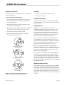
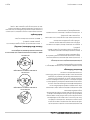
Lighting Instructions
For speci c models see “Lighting Instructions” on the inside
of fryer compartment.
(Frypot must be lled before lighting).
1. Turn thermostat knob to the frying temperature. The
thermostat knob is located inside the compartment in
the front of the frypot.
2. Open the fryer door and turn the combination safety
valve knob to the PILOT position.
3. Push the knob in, light the pilot and continue to hold knob
in for about sixty seconds after the ame has been lit.
4. Turn valve knob counter-clockwise to ON.
5. Main burners will now light and will be controlled
automatically by the thermostat
NO
OFF
P
I
L
O
T
NO
OFF
P
I
L
O
T
NO
OFF
P
I
L
O
T
AUTOMATIC VALVE KNOB
PILOT POSITION
AUTOMATIC VALVE KNOB
ON POSITION
AUTOMATIC VALVE KNOB
OFF POSITION
NOTE: Fryer cannot be shut o at the thermostat.
Thermostat used only to control temperatures.
Stand By
1. Turn fryer gas valve knob to “PILOT” position.
2. Put frypot cover in place.
Complete Shut Down
Turn gas valve knob clockwise to pilot position, DEPRESS
knob, slightly clockwise, release knob and continue turning
clockwise to OFF.
Safety Concerns
WARNING: The operator should be aware of the
HAZARDOUS NATURE, inadvertent splashing and spilling
etc., and RESULTANT CONSEQUENCES, personal burns,
res, slipping on spilled liquid etc., when moving the fryer
with liquid in the vessel. If the fryer is to be moved, it is
recommended that the liquid in the vessel be cooled to
room temperature and removed from the vessel.
To assure you of maximum protection and performance
your GARLAND Fryer is equipped with the best and most
reliable controls and safety devices available. The operation
thermostat will regulate frying compound temperatures to
close tolerances in a range between 250° and 375°.
If for any reason the pilot should be extinguished the
combination safety valve will close o the gas ow to the
main burners and pilot burner. As an additional safety feature
this valve prevents gas from owing to the main burners
when the pilot is being ignited.
On all units, due to the high rate of heating, and high limit
control device is provided as standard equipment. If for
any reason the frying compound temperature exceed the
maximum dial temperature the entire fryer will turn OFF at
450°F. If this should occur, have quali ed service technician
check the system. FOR NO REASON SHOULD THIS HIGH LIMIT
DEVICE BE BY-PASSED!
Optimum Operation Tips
One of the most important considerations in the pro table
use of a fryer is the choice of the frying compound used. A
better frying compound will actually cost you less, because
it lasts longer than the lower grades and produce fried foods
with superior taste and appearance. There are numerous
high-grade products available and you are strongly urged to
use them.

Part # 1382677 - 2/15
Page 12
For maximum frying compound life, good operators nd
they do best by frying at the lowest temperature that will
give a high-quality product. Thus, with a super-fast fryer,
such as your GARLAND, you do not have to fry potatoes at
375°F or 400°F, your fry at 325°F. A little experimenting will
determine just the right temperatures for your menu items.
The worst enemies of frying compound are light, heat,
air and salt. Thus, its life can materially be lengthened by
keeping the fryer covered when not in use, frying at the
lowest temperatures, and by reducing the temperatures
during stand-by periods.
A common habit which is harmful to frying compounds is
that of salting foods in baskets over frypot. Also, if food is
fried ahead and stored over the frypot to keep hot, as is often
done, it will rapidly lose its crispness and will taste greasy.
A common error in frying is to overload the baskets
under the mistaken impression that this will increase the
production of the fryer. For any given fryer, and any given
food product being fried there is a certain load which will
produce the maximum amount of food per hour. For best
results, we recommend the baskets be lled between ½ and
⁄ full. If the baskets are loaded beyond this, the total hourly
production rate will decrease.
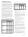
To give you a staring point, the following chart suggests the
temperatures at which most operators fry certain foods:
FRYING CHART
PRODUCT
TEMPERATURE
TIME
(
0
F) (
0
C)
French Fried Potatoes
Raw-to-done 350 177 5-7 Min
Blanching 325 163 4 Min
Browning
350 177 2 Min
French Fried Onion Rings 360 182 2-3 Min
Seafood
Shrimp 360 182 2-3 Min
Oysters 350 177 1-4 Min
Scallops 250 121 3-5 Min
Fillets 350 177 3-4 Min
Clams 350-360 177-182 1-3 Min
Chicken
Small Pieces 350 177 6-10 Min
Large Pieces 350-360 177-182 8-11 Min
Cutlets, Chops (1” thick)
325 163 5-7 Min
OPERATION Continued
FRYING CHART
PRODUCT
TEMPERATURE
TIME
(
0
F) (
0
C)
Fritters
Fruit 350 177 3-5 Min
Vegetables (asparagus,
cauli ower, corn,
eggplant, tomato)
350 177 5-8 Min
Suggestions for Quality Fried Food
• Fresh, uncontaminated frying compound product better
fried products.
• Taste the frying compound once a day. Your patrons do,
when they eat the product.
• Filter the frying compound daily. Merely straining the
shortening is inadequate. You may choose the GARLAND
Filter Quick ltering system. This system is designed to
match-up to your GARLAND Fryer. Or, you may choose to
use a lter and lter cone.
• Drain or dry foods before frying. Excess moisture and
water breaks down frying compound.
• Do not salt or otherwise season food over the fryer.
This practice contaminates the frying compound and
accelerates it deterioration.
• Do not shake breaded items over the fryer.
• Keep the frypot covered when not in use. This will
prevent air from oxidizing the frying compound and will
keep impurities out.
• Do not overheat the frying compound. Follow the
temperature recommended in tested recipes. The
company which provides your frying compound can
provide tested recipes and techniques for use with their
shorting.
• Watch for signs of compound breakdown. An unusual
darkening of the compound or smoking are the rst signs
of breakdown. Foaming, objectionable change in avour
of the product and gumming also indicate a breakdown
of the frying compound.
• Set the thermostat at 200°F or below, when not frying.
• Darkened frying compound and incorrect batter or
breading can cause a fried product to appear to be done.
Use tested recipe or obtain batter or breading specially
prepared for today’s frying techniques.

Part # 1382677 - 2/15
Page 13
CLEANING AND MAINTENANCE
Routine Care
NEVER operate the burner with an empty frypot. It only takes
a few minutes to completely ruin a frypot this way, and the
frypot warranty is void if this is done.
The frying compound should be ltered at least once a day. If
a heavy volume of breaded food is fried, it may be necessary
to lter two or more times a day. This will increase the life
of the frying compound and produce better-tasting food.
GARLAND lter cones are ideal for this and are inexpensive
and readily obtainable from your dealer or parts distributor.
The fryer should be cleaned daily, and this operation can
be combined with ltering the frying compound. After the
fryer is drained, wipe the inside with cloth saturated in a
commercial fryer/griddle cleaner, then rinse thoroughly.
Wipe dry and put the ltered compound back in the
frypot. The frypot should be boiled out once a week with a
commercial fryer/griddle cleaner according to direction on
the bottle. Each day wipe down the controls and all inside
the door with a damp cloth. Remove the basket hanger and
clean at least once a week. This way your fryer will stay clean
and new looking much longer. Be sure that the grease cover
for the automatic gas valve is kept in place.
Cleaning
Painted Finishes
Establish a regular cleaning schedule. Any spills should be
wiped o immediately.
The fryer should be permitted to cool down before cleaning
exterior surfaces.
1. Wipe exposed, cleanable surface when cool with a mild
detergent and hot water. Stubborn residue spots may be
removed with a light weight non metallic scouring pad.
Dry thoroughly with a clean cloth.
2. Stainless steel should be cleaned using a mild detergent,
a soft cloth and hot water. If necessary to use a
nonmetallic scouring pad, always rub in the direction of
the grain in the metal to prevent scratching. Use a water
based stainless cleaner (commercially available), if you
want a high shine.
Stainless Steel
For routine cleaning just wash with a hot water and
detergent solution. Wash just a small area at a time or the
water will evaporate leaving chemicals behind causing
streaking. Rinse the washed area with a clean sponge dipped
in a sanitizing solution and wipe dry with a soft clean cloth
before it can dry. Use a paste (of water and a mild scouring
powder) if you have to, but never rub against the grain.
All stainless steel has been polished in one direction. Rub
with the polish lines to preserve the original nish. Then
thoroughly rinse as before. To prevent ngerprints there
are several stainless steel polishes on the market that leave
an oily or waxy lm. Do not use on surfaces that will be in
contact with food.
Stainless steel may discolor if overheated. These stains can
usually be removed by vigorous rubbing with a scouring
powder paste. Use only stainless steel, wood or plastic tools
it necessary to scrape o heavy deposits of grease and oil.
Do not use ordinary steel scrapers or knives as particles of
iron may become imbedded and rust. STEEL WOOL SHOULD
NEVER BE USED. Either a typical bleach solution or hot water
can be use to sanitize stainless steel with harm.
Draining and Filtering Of Fryer Compound
The draining and ltering of fryer compound must be
accomplished with care to avoid the possibility of a burn
resulting from careless handling.
Filtering: Turn fryer o . If you are using a lter other than the
GARLAND Filter Quick, consult the ltering manufactures’
operation instructions for recommended ltering procedure.
Instructions for use of the lter Quick are included in the
Owners Manual shipped with your lter Quick unit.
The following is a recommended procedure to drain and
lter your compound when no lter machine is available:
1. Screw the drain pipe provided with your fryer into the
drain valve. Assure that you have rmly attached the
drain pipe and that the curved end portion is pointing
“down.”

Part # 1382677 - 2/15
Page 14
2. Position the stock pot or other container under the
drain pipe. The stock pot or other container must be of
su cient design to withstand the heat generated by the
hot compound and must also be able to hold liquids. It is
recommended that where no lter machine is available,
the lter cone holder and lter cones be used. Be sure the
lter cone holder is resting securely on the stock pot or
other container.
3. Open the drain valve slowly to avoid splattering.
However, since splattering may occur anyway, extreme
caution should always be employed.
4. If the valve becomes clogged with food particles you
may wish to use a poker-like tool. The tool must be used
from the inside of the frypot only and caution should be
employed that the tool is gripped by the user as far as
possible from the hot fryer compound in the frypot. Do
not hammer on the drain valve as damage to the ball
inside the valve will cause it to leak. NEVER use this tool
or any other tool to unclog the valve from the front of the
valve. If the clog comes loose, hot compound could pour
out rapidly so beware of splattering in this event.
5. We recommend that the drained compound be allowed
to cool to 100ºF (38ºC) or lower before transporting the
stock pot or other container, removing the drain pipe, or
removing the lter cone holder and lter cone.
CLEANING AND MAINTENANCE Continued
Maintenance
Your GARLAND equipment is ruggedly constructed and is
designed, with normal care, to give you long and lasting
service. It is, of course, desirable to keep your equipment
in the best possible condition. As the equipment is used,
whether in light or heavy duty service, it should be cleaned
often and a regular cleaning schedule should be established
on a daily, week and/or monthly basis, depending upon
severity of use.
Preventive Maintenance
In order to keep the unit operation at top e ciency, it is
advisable to perform preventive maintenance regularly. The
frequency of this maintenance will depend on how hard the
unit is used, and you should discuss this with your nearest
GARLAND authorized Service Agent.
Preventive maintenance should cover at least the following:
1. Check pilot ame for correct length.
2. Check main burner ames for good ignition and proper
burner adjustment.
3. Check thermostat calibration.
4. Check thermopile output.
5. This fryer needs no lubrication.

Part # 1382677 - 2/15
Page 15
TROUBLE SHOOTING AND ADJUSTMENTS
Adjustments
The burner used on your GARLAND Fryer is a patented
design which does not require primary air, so no primary air
adjustment is possible. When the proper gas is being used,
at the proper pressure, and the ceramic targets are adjusted
properly, combustion will begin about even with the bottom
of the ceramic. The sound that is characteristic is a low roar,
similar to a blowtorch.
The correct type of gas and BTU content for which the fryer
was equipped at the factory is noted on the nameplate, and
this gas must be used.
NEVER THROTTLE DOWN THE INCOMING GAS IN AN EFFORT
TO MAKE THE FLAME BURN DIRECTLY ON THE ORIFICE.
Trouble Shooting
Possible Causes Remedy
1
Thermostat does not call for heat
(does not open gas valve at all).
1 See Below:
a. Lead wires damaged. a. Repair or replace wires on thermostat.
b. Set too low. b. Raise setting.
c. Out of calibration c. Re-calibrate
d. Thermostat defective d. Replace
2. Thermostat does not control set point 2 See Below:
a. Out of calibration. a. Re-calibrate
b. Contaminated or burned contacts b. Replace thermostat
c. Knob of thermostat loose on shaft c. Calibrate thermostat and tighten set screws.
A piece of mechanical equipment which is used as hard as
a deep fat fryer is going to require service as the fryer gets
older; therefore, the following chart outlines problems that
are most likely to occur and what to do to correct them.
There are several possible sources of trouble in connection
with the operating thermostat. Usually the trouble will be
noticed by either the thermostat not causing the gas valve to
open, or by causing it to open at the wrong temperature. If
it opens the gas valve at the wrong temperature, it is said to
be out of calibration. If all the other parts of the appliance are
operation as they should, the following chart will help locate
the source of trouble and correct it.

Part # 1382677 - 2/15
Page 16
TROUBLE SHOOTING AND ADJUSTMENTS Continued
Thermostat Calibration
To calibrate the Fenwal Thermostat, ll the frypot to the FULL
mark with frying compound and turn the burner on. Insert a
thermometer in the center of the frypot with the bulb about
two inches below the surface. Allow the burner to cycle
about four times, the thermometer reading should be within
5° of the thermostat knob setting. If this does not agree with
the pointer of the thermostat knob:
1. Loosen the two set screws on the thermostat knob
2. Set the pointer at the temperature indicated on the
thermometer.
3. Tighten the set screws rmly.
4. Be sure the black surface of the knob is spaced away
from the dial plate at least the thickness of a dime.
NOTE: DO NOT TURN ADJUSTING SHAFT MORE THAN TWO
TURNS IN EITHER DIRECTION OR PERMANENT DAMAGE CAN
RESULT. THIS ACTION MAY VOID THE STANDARD WARRANTY.
The Fenwal Thermostat is an electric switch with contacts
that open on a temperature rise. It will respond to
temperature changes of approximately 1º when the fryer is
idling with no food being fried.
Turning the adjusting shaft counter-clockwise increases the
temperature at which time the contacts will open. Some of
the most common problems occur in connection with the
pilot generator. These usually show as poor ignition of the
main burner or frequent pilot outage.
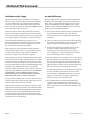
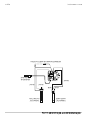
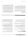
Below is a diagram of how the Fenwal thermostat and Hi-
Limit controls are wired to the safety system.
BLK BLK WHT WHT
HI-LIMIT
THERMOSTAT
OPERATING
THERMOSTAT
PILOT
GENERATOR
OPTIONAL ON OFF SWITCH

Part # 1382677 - 2/15
Page 17

GARLAND
1177 KAMATO ROAD, MISSISSAUGA, ONTARIO, CANADA, L4W1X4
8884427526
WWW.GARLANDGROUP.COM
To learn how Manitowoc Foodservice and its leading brands can equip you, visit our global web site at
www.manitowocfoodservice.com, then discover the regional or local resources available to you.
©2014 Manitowoc Foodservice except where explicitly stated otherwise. All rights reserved. Continuing product improvement may necessitate change of speci cations without notice.
Every new piece of Manitowoc Foodservice equipment comes with KitchenCare™ and you choose the level of service that meets
your operational needs from one restaurant to multiple locations.
StarCare – Warranty & lifetime service, certi ed OEM parts, global parts inventory, performance audited
ExtraCare — CareCode, 24/7 Support, online/mobile product information
LifeCare – Install & equipment orientation, planned maintenance, KitchenConnect™, MenuConnect
Talk with KitchenCare™ • 1-844-724-CARE • www.mtwkitchencare.com

Pièce nº 1382677 (2/15) Page 17
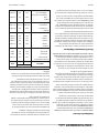
DÉPANNAGE ET RÉGLAGES suite
NOIR NOIR
BLANC
THERMOSTAT
HAUTE LIMITE
THERMOSTAT
EN FONCTION
GÉNÉRATEUR
DE VEILLEUSE
INTERRUPTEUR MARCHE/ARRÊT EN OPTION
BLANC
BLANC
La page charge ...
La page charge ...
La page charge ...
La page charge ...
La page charge ...
La page charge ...
La page charge ...
La page charge ...
La page charge ...
La page charge ...
La page charge ...
La page charge ...
La page charge ...
La page charge ...
La page charge ...
La page charge ...
-
 1
1
-
 2
2
-
 3
3
-
 4
4
-
 5
5
-
 6
6
-
 7
7
-
 8
8
-
 9
9
-
 10
10
-
 11
11
-
 12
12
-
 13
13
-
 14
14
-
 15
15
-
 16
16
-
 17
17
-
 18
18
-
 19
19
-
 20
20
-
 21
21
-
 22
22
-
 23
23
-
 24
24
-
 25
25
-
 26
26
-
 27
27
-
 28
28
-
 29
29
-
 30
30
-
 31
31
-
 32
32
-
 33
33
-
 34
34
-
 35
35
-
 36
36


Garland 36ER33-88 Owner Instruction Manual
- Catégorie
- Cuisinières
- Taper
- Owner Instruction Manual
dans d''autres langues
- English: Garland 36ER33-88
Documents connexes
-
Garland M70 Mode d'emploi
-
-
-
Garland E20 Series Manuel utilisateur
-
Garland GD-18RBFF Mode d'emploi
-
-
-
-
Garland ED-24G Mode d'emploi
-
Autres documents
-
home HM-DF-B240SS Manuel utilisateur
-
home HM-DF-G360SS Manuel utilisateur
-
Power Fist 8901258 Le manuel du propriétaire
-
Toastmaster TMFG18-NAT Mode d'emploi
-
Star Manufacturing 630FD Mode d'emploi
-
-
ROLLER GRILL 304111 Manuel utilisateur
-
-
Graef FR 1490 Fiche technique
-
 Frymaster CF Manuel utilisateur
