Tele Radio AB Panther PN-R8-6 Manuel utilisateur
- Taper
- Manuel utilisateur

TELE RADIO
PANTHER
Installation instructions
PN-RX-MN5 (PN-R8-1), PN-RX-MD11 (PN-R8-6), PN-RX-MN5E (PN-R8-10),
PN-RX-MD11E (PN-R8-11), PN-TX-MD3M (PN-T13-3), PN-TX-MD6M (PN-T13-6),
PN-TX-MD8M (PN-T13-8), PN-TX-MD10M (PN-T13-10), PN-TX-MD3 (PN-T21-3),
PN-TX-MD6 (PN-T21-6), PN-TX-MD8 (PN-T21-8), PN-TX-MD10 (PN-T21-10),
PN-TX-MN3 (PN-T7-16), PN-TX-MN6 (PN-T7-15), PN-TX-MN8 (PN-T7-14)
Language: English (original)
IM-PN-RX010-A04-EN

CONTENTS
Chapter 1: CUSTOMER INFORMATION 3
Chapter 2: PRODUCT PAGES 5
PN-RX-MN5, PN-RX-MN5E Base board receiver 5
PN-RX-MD11, PN-RX-MD11E Base board receiver with a Relay expansion board 7
PN-TX-MD, PN-TX-MDM, PN-TX-MN Transmitters 12
Chapter 3: INSTALLERS GUIDE 15
Default radio mode 15
Start the transmitter 15
Register the transmitter in the receiver 15
Erase all transmitters from the receiver 16
Turn the transmitter off 16
Frequencies & channels 16
Logout 17
Make a Load selection 18
Relay functionality 18
Operating mode 1 19
Chapter 4: BATTERY GUIDE 20
Chapter 5: CERTIFICATIONS CHAPTER 22

Chapter 1: CUSTOMER INFORMATION
CHAPTER 1: CUSTOMER INFORMATION
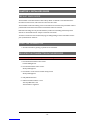
THANK YOU FOR PURCHASING A TELE RADIO AB PRODUCT
READALLINSTRUCTIONS ANDWARNINGS CAREFULLY BEFOREMOUNTING, INSTALLING
ANDCONFIGURATING THEPRODUCTS.
These instructions are published by Tele Radio AB without any guarantee. The instructions may be
removed or revised by Tele Radio AB at any time and without further notice. Corrections and additions
will be added to the latest version of the instruction.
IMPORTANT! These instructions are directed to installers. There are separate instructions directed
towards end users. The instructions that contain information on the installation and configuration of the
radio remote control unit on the machine are not intended to be passed on to the end user. Only such
information may be passed on to the end user that is needed to operate the machine correctly by radio
remote control.
Tele Radio AB products are covered by a guarantee/ warranty against material, construction or
manufacturing faults. During the guarantee/ warranty period, Tele Radio AB may replace the product or
faulty parts with new. Work under guarantee/ warranty must be carried out by Tele Radio AB or by an
authorized service center specified by Tele Radio AB. Contact your Tele Radio AB representative if you
need support or service.
©Tele Radio AB
Datavägen 21
SE-436 32 ASKIM
SWEDEN
Tel: +46-31-748 54 60
Fax: +46-31-68 54 64
www.tele-radio.com
-3-

Chapter 1: CUSTOMER INFORMATION
WARNINGS & RESTRICTIONS
WARNING! Tele Radio remote controls are often built into wider applications. We recommend that
the system is provided with a wired emergency stop where necessary.
INSTALLING, CONNECTING AND MOUNTING
nAllow only licensed or qualified personnel to install the product.
nSwitch the power supply off to the receiver before connecting the equipment.
nCheck that you have connected the power supply to the correct connection terminal.
nTo utilize the safety of the system, use the stop relays in the safety circuitry of the object that you
want to control.
nUse undamaged cables. No cables should hang loose.
nAvoid installing in areas affected by strong vibrations.
nPlace the receiver well away from wind, damp and water.
nCable glands and vent plugs must face down to prevent water from seeping in.
THE USER
nMake sure that the user is following the instructions.
nMake sure that the user has reached the certified age of your country to operate the equipment.
nMake sure that the user is not under the influence of drugs, alcohol and medicines.
nAllow only qualified personnel to have access to the transmitter and operate the equipment.
nMake sure that the user does not leave the transmitter unsupervised.
nMake sure that the user always turns the transmitter off when not in use.
nMake sure that the user keeps a good overview of the work area.
MAINTENANCE
nUse the stop button to start and turn off the transmitter as often as possible.
nWhen error messages are shown, it is very important to find out what caused them.
nIf the stop button is mechanically damaged, contact your representative for service immediately.
nAlways contact your representative for service and maintenance work on the product.
nWrite down the serial numbers/ ID codes of the receivers and transmitters used. This inform-
ation should be recorded on the “Settings document” for your product (download from our web-
site).
nAvoid registering transmitters to receivers where it is not being used.
nKeep the safety instruction for future reference. Always download the configurations instruction
from our web site for the latest version available.
-4-

Chapter 2: PRODUCT PAGES
CHAPTER 2: PRODUCT PAGES
PN-RX-MN5, PN-RX-MN5E BASE BOARD RECEIVER
WARNING! The receiver must NOT be opened by any other than a qualified installer. Make sure to
turn the electricity off before opening the receiver.
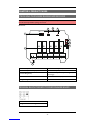
Base board:
CO NO NC CO NO NC CO NO NC CO NO NC CO NO NC
5 1 2 3 4
1 2 3 4 5136 7 8 9 10 11 12 14 15 16 17
LEDs
5 1 2 3 4
LED7
LED10
LED8
LED9
LED6
R5 R1 R2 R3 R4
1
2
345
6
7
8
9
12-24V DC
+ -
1. Function relays 1-5 6. Function button (cancel)
2. Function relay LEDs 1-5 (red) 7. Select button (OK)
3. Power LED (yellow) 8. Function LEDs (7=red, 8=yellow, 9=green,
10=orange)
4. Radio module 9. Terminal block for input power
5. Programming connector
TERMINAL BLOCK FOR INPUT POWER ON BASE BOARD
1. 12 - 24V DC
2. Negative terminal DC voltage
-5-

FUNCTION LEDS INDICATION IN OPERATING MODE
FunctionLED Off On Indicates
7 (red)
x No transmitter is registered.
x Flashes once: One or more transmitters are registered. No radio transmission
established.
x Double flash: One or more transmitters are registered and logged in. No radio
transmission established.
x Radio transmission established.
8 (yellow) x Receiving a radio packet from a transmitter other than a Panther.
8 (yellow)
9 (green) x Receiving a radio packet from a transmitter set to the radio mode different from
that of a receiver.
8 (yellow)
10 (orange) x Receiving a radio packet from a transmitter that is not registered.
9 (green) x Receiving a radio packet, low signal (RSSI).
10 (orange) x Receiving a radio packet, configuration ID not accepted.
9 (green)
10 (orange) x Receiving a radio packet, custom ID not accepted.
8 (yellow)
9 (green)
10 (orange)
x
1. Receiving a radio packet from a registered transmitter. The receiver is
already controlled by another registered transmitter. NOTE! "Radio link" must
be activated in the receiver.
2. Load select mode is activated. Incorrect Load is selected on the transmitter.
-6-

PN-RX-MD11, PN-RX-MD11E BASE BOARD RECEIVER WITH A
RELAY EXPANSION BOARD
WARNING! The receiver must NOT be opened by any other than a qualified installer. Make sure to
turn the electricity off before opening the receiver.
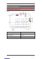
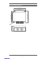
Base board:
1. Function relays 1-5 6. Function button (cancel)
2. Relay LEDs 1-5 (red) 7. Select button (OK)
3. Power LED (yellow) 8. Function LEDs (7=red, 8=yellow, 9=green,
10=orange)
4. Radio module 9. Terminal block for input power
5. Programming connector
-7-

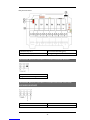
Relay expansion board:
10. Function relays 6-11 12. Communication LED (green)
11. Relay LEDs 6-11 (red) 13. Programming connector
TERMINAL BLOCK FOR INPUT POWER ON BASE BOARD
1. 12 - 24V DC
2. Negative terminal DC voltage
TERMINAL BLOCK FOR INPUT POWER ON HIGH VOLTAGE
EXPANSION BOARD
21. Common 23. 24-110V AC
22. Common 24. 230V AC
-8-

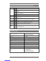
FUNCTION LEDS INDICATION IN OPERATING MODE
FunctionLED Off On Indicates
7 (red)
x No transmitter is registered.
x Flashes once: One or more transmitters are registered. No radio transmission
established.
x Double flash: One or more transmitters are registered and logged in. No radio
transmission established.
x Radio transmission established.
8 (yellow) x Receiving a radio packet from a transmitter other than a Panther.
8 (yellow)
9 (green) x Receiving a radio packet from a transmitter set to the radio mode different from
that of a receiver.
8 (yellow)
10 (orange) x Receiving a radio packet from a transmitter that is not registered.
9 (green) x Receiving a radio packet, low signal (RSSI).
10 (orange) x Receiving a radio packet, configuration ID not accepted.
9 (green)
10 (orange) x Receiving a radio packet, custom ID not accepted.
8 (yellow)
9 (green)
10 (orange)
x
1. Receiving a radio packet from a registered transmitter. The receiver is
already controlled by another registered transmitter. NOTE! "Radio link" must
be activated in the receiver.
2. Load select mode is activated. Incorrect Load is selected on the transmitter.
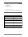
TECHNICAL DATA
Number of function relays
PN-RX-MN5, PN-RX-MN5E: 5
PN-RX-MD11, PN-RX-MD11E: 11
(potential free*, 10A, 250V AC)
Input power 12-24V DC
Digital inputs 8
Duplex communication No
Max. number of registered transmitters 8
IP class 66
Size 120 x 117 x 51 mm / 4.7 x 4.6 x 2 in
Weight 400 g / 0.8 lbs
Operating temperature -20 - +55 °C / -4 - +130 °F
Operating frequency 2405-2480 MHz
Number of channels 16 (channel 11-26)
Channel separation 5 MHz
Antenna
PN-RX-MN5, PN-RX-MD11:
1 internal PCB antenna
PN-RX-MN5E, PN-RX-MD11E:
1 external antenna, reversed SMA
*potential free means that you have to supply voltage to get voltage out of a relay
-9-

CURRENT CONSUMPTION
Input power Min.* Max.**
12V DC 0.02A 0.3A
24V DC 0.02A 0.2A
24V AC 0.02A 0.2A
48V AC 0.01A 0.05A
110V AC 0.005A 0.03A
230V AC 0.01A 0.02A
*Minimum current consumption= Receiver powered, no radio session established, nothing else
activated on the receiver.
**Maximum current consumption= All relays activated on the receiver.
ANTENNA - MOUNTING DESCRIPTION
NOTE! For optimum performance: Place well away from metal objects, such as metal girders, high-
voltage cables and other antennas.
lAntenna with cable - cable makes it possible for the antenna to be positioned freely and high
above the ground.
lAntenna without cable - if the receiver is installed on a wall, the antenna should be angled out
from the wall.
-10 -


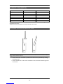
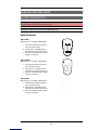
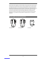
PN-TX-MD, PN-TX-MDM, PN-TX-MN TRANSMITTERS
PN-TX-MD PN-TX-MDM PN-TX-MN
1. LED 1 (red) 1. LED 1 (red) 1. LED 1 (red)
2. LED 2 (red) 2. Top LED (red, green) 2. Top LED (red, green)
3. Top LED (red, green) 3. LED 2 (red) 3. LED 2 (red)
4. LED 3 (red) 4. Buttons (1-10) 4. Buttons (1-8)
5. LED 4 (red)
6. Buttons (1-10)
-12 -

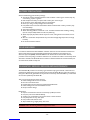
TRANSMITTER BACKSIDE
PN-TX-MD PN-TX-MDM PN-TX-MN
1. On/Off switch 1. On/off switch 1. On/off switch
2. Clip 2. Clip 2. Clip
3. CE/FCC/IC label 3. CE/FCC/IC label 3. CE/FCC/IC label
ON/OFF SWITCH
The transmitter has an on/off switch on the
backside. The switch breaks the power supply
from the battery. When in position 0/off, the
transmitter cannot be started unless you connect
the charger plug. When the transmitter is
transported by airplane, the on/off switch must be
in 0/off position. The switch should not be used as
an on/off button for the transmitter.
-13 -

TECHNICAL DATA
NO. OFBUTTONS
PN-TX-MD3, PN-TX-MD3M, PN-TX-MN3 3 x 1-step button
PN-TX-MD6, PN-TX-MD6M, PN-TX-MN6 6 x 1-step button
PN-TX-MD8, PN-TX-MD8M, PN-TX-MN8 8 x 1-step button
PN-TX-MD10, PN-TX-MD10M 10 x 1-step button
BATTERY
PN-TX-MD 3 x 1.5V AAA
PN-TX-MDM, PN-TX-MN 2 x 1.5V AAA
ON/OFF SWITCH
PN-TX-MD, PN-TX-MDM, PN-TX-MN Yes
DUPLEX COMMUNICATION
PN-TX-MD, PN-TX-MDM, PN-TX-MN No
ANTENNA
PN-TX-MD, PN-TX-MDM, PN-TX-MN 1 internal PCB antenna
SIZE
PN-TX-MD 66 x 114 x 37.5 mm / 2.6 x 4.5 x 1.5 in
PN-TX-MDM 66 x 114 x 37.5 mm / 2.6 x 4.5 x 1.5 in
PN-TX-MN 52 x 83 x 17 mm / 2 x 3.3 x 0.7 in
WEIGHT
PN-TX-MD 135 g (0.29 lbs)
PN-TX-MDM 135 g (0.29 lbs)
PN-TX-MN 70 g (0.15 lbs)
OPERATING FREQUENCY
PN-TX-MD, PN-TX-MDM, PN-TX-MN 2.4 GHz
NO. OF CHANNELS
PN-TX-MD, PN-TX-MDM, PN-TX-MN 16 (channel 11-26)
CHANNEL SEPARATION
PN-TX-MD, PN-TX-MDM, PN-TX-MN 5 MHz
IP CLASS
PN-TX-MD, PN-TX-MDM 67
PN-TX-MN 65
OPERATING TEMPERATURE
PN-TX-MD, PN-TX-MDM, PN-TX-MN -20 - +55 °C / -4 - +130 °F
-14 -

Chapter 3: INSTALLERS GUIDE
CHAPTER 3: INSTALLERS GUIDE
DEFAULT RADIO MODE
The transmitter is set to discontinuous radio mode by default. To establish a radio link between the
transmitter and the receiver, both need to be in the same radio mode.
The transmitter will start transmitting as soon as the batteries are inserted and any transmitter button is
pressed. Radio transmission will end when all transmitter buttons are released.
Note that some settings can only be made when the products are transmitting continuously. Those
sections are marked with the text: "Only for continuous radio mode".
To switch to continuous radio mode, the PC-program Settings Manager must be used. Please contact
your representative for assistance.
START THE TRANSMITTER
1. Start the transmitter by pressing any button on the transmitter.
REGISTER THE TRANSMITTER IN THE RECEIVER
WARNING! Keep only transmitters, that you intend to use, registered in the receivers.
1. Press the Function button on the receiver.
Function LED lights red.
2. Press the Select button on the receiver.
All relay LEDs light red.
3. Press button 1 and 2 on the transmitter. Keep pressed.
All relay LEDs light red.
4. Relay LEDs flash 2 times.
5. Release transmitter buttons 1 and 2.
The relay LEDs flash 1 time.
The transmitter is registered.
-15 -

Chapter 3: INSTALLERS GUIDE
ERASE ALL TRANSMITTERS FROM THE RECEIVER
1. Press the Function button on the receiver.
Function LED lights red.
2. Press the Select button on the receiver.
All relay LEDs light red.
3. All relay LEDs go out.
4. Release the Select button.
All transmitters are erased from the receiver.
If the red function LED flashes, one or more transmitters are still registered in the receiver.
TURN THE TRANSMITTER OFF
1. The transmitter turns off when no transmitter button is pressed.
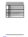
FREQUENCIES & CHANNELS
Channel Frequency
11 2405
12 2410
13 2415
14 2420
15 2425
16 2430
17 2435
18 2440
19 2445
20 2450
21 2455
22 2460
23 2465
24 2470
25 2475
26 2480
-16 -

Chapter 3: INSTALLERS GUIDE
Switch channel
NOTE! Only for the PN-TX-MD and when in continuous radio mode.
1. Start the transmitter. The top LED flashes green.
2. Press the Off-button on the transmitter. Keep pressed. The top LED flashes red.
3. Within 2 seconds, press and hold button 1 or button 3 to switch channel.
Button 1 = +1
Button 3 = -1
Top LED lights green. The channel is changed. The channel number is indicated by LED 1 and
LED 4.
Ex. channel 26: LED 1 flashes 2 times, LED 4 flashes 6 times.
4. The transmitter switches off.
LOGOUT
NOTE! Only for the PN-TX-MD and when in continuous radio mode.
NOTE! Logout function is deactivated by default. Contact your representative for assistance.
Logout from the receiver
1. Press the receiver Select button. LED 10 (orange) lights.
2. Keep pressed (at least 4 seconds). LED 10 (orange) goes off.
3. The transmitter is now logged off. Any other registered transmitter can be logged in.
Quick logout
There are two alternatives for logging out from the transmitter.
Alternative 1:
1. Press the Logout-button on the transmitter. Keep pressed.
2. Press the Off-button. The top LED lights red.
3. The transmitter switches off after logging out.
Alternative 2:
1. Press the Off-button. Keep pressed.
2. Within 2 seconds, press the Logout-button. The top LED lights red.
3. The transmitter switches off after logging out.
-17 -

Chapter 3: INSTALLERS GUIDE
AUTOMATIC SHUTDOWN
NOTE! You can not change the automatic shutdown time from the transmitter. Contact your
representative for assistance.
The transmitter automatic shutdown time is set to 3 minutes by default.
MAKE A LOAD SELECTION
Load select mode for the transmitter PN-TX-MDM, PN-TX-MN and PN-TX-MD is deactivated by
default (Load select mode 0).
NOTE! The loads are selected in the PC program Settings Manager. Contact your representative for
assistance.
RELAY FUNCTIONALITY
NOTE! If Operating mode 0 is selected, you can not make these settings. Contact your representative
for assistance.
NOTE! Momentary relay functionality is default. That means that the relay will only be activated when
you press a button on the transmitter. When the button is released, the relay deactivates. Setting a relay
to latching means that the relay gets activated every time that you press a button, but in this case the
relay remains active until the button is pressed again.
NOTE! The settings options depend on the selected Operating mode.
Momentary or latching relay functionality
1. Press the receiver Function button 2 times. LED 8 (yellow) lights. The relay LEDs light.
2. Press the receiver Select button to switch relay functionality. The relay LEDs flash to indicate that a
latching or momentary functionality can be set to the corresponding relays.
3. Press the receiver Function button to set latching or momentary functionality:
LED 8 (yellow) off = momentary relay functionality
LED 8 (yellow) on = latching relay functionality
4. Press the receiver Select button to step to the next available relay. When you have stepped through
all the available relays, the receiver exits the settings menu.
-18 -


Chapter 4: BATTERY GUIDE
CHAPTER 4: BATTERY GUIDE
BATTERY INFORMATION
WARNING! Do not recharge the batteries. Attempts to recharge may cause rupture or the leaking of
hazardous liquids, which will corrode the equipment.
NOTE! Electronics and batteries must be physically separated before disposal. Make sure that
electronics or batteries are not thrown in the household waste.
Switch batteries
PN-TX-MD
Battery type: 3 x 1.5V AAA / LR03 Alkaline
1. Take off the transmitter backside by
unscrewing the 5 screws.
2. Switch the 3 x 1.5V AAA batteries.
Use alkaline for optimal performance.
3. Put the transmitter backside on again
using the screwdriver.
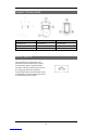
PN-TX-MDM
Battery type: 2 x 1.5V AAA / LR03 Alkaline
+
+
-
-
1. Take off the transmitter backside by
unscrewing the 5 screws.
2. Switch the 2 x 1.5V AAA batteries.
Use alkaline for optimal performance.
3. Put the transmitter backside on again
using the screwdriver.
PN-TX-MN
Battery type: 2 x 1.5V AAA / LR03 Alkaline
1. Take off the transmitter backside by
unscrewing the 3 screws.
2. Switch the 2 x 1.5V AAA batteries.
Use alkaline for optimal performance.
3. Put the transmitter backside on again
using the screwdriver.
-20 -
La page est en cours de chargement...
La page est en cours de chargement...
La page est en cours de chargement...
La page est en cours de chargement...
La page est en cours de chargement...
La page est en cours de chargement...
La page est en cours de chargement...
La page est en cours de chargement...
-
 1
1
-
 2
2
-
 3
3
-
 4
4
-
 5
5
-
 6
6
-
 7
7
-
 8
8
-
 9
9
-
 10
10
-
 11
11
-
 12
12
-
 13
13
-
 14
14
-
 15
15
-
 16
16
-
 17
17
-
 18
18
-
 19
19
-
 20
20
-
 21
21
-
 22
22
-
 23
23
-
 24
24
-
 25
25
-
 26
26
-
 27
27
-
 28
28


Tele Radio AB Panther PN-R8-6 Manuel utilisateur
- Taper
- Manuel utilisateur
dans d''autres langues
Autres documents
-
Quick R908 Manual Of Installation And Use
-
-
HPI Racing TF-45/RF-40 Radio Manuel utilisateur
-
 Remtron Command Pro 21R10 Manuel utilisateur
-
Extron XTP R HD 4K Manuel utilisateur
-
Cervis Warrior MU-X9 System Manual
-
-
Clear-Com DX340ES Mode d'emploi
-
Key Gates KCOMW Mode d'emploi
-
