
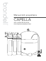
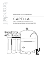
Owner's Manual
CAPELLA
H2O+ REVERSE OSMOSIS
WATER FILTRATION SYSTEM RC250

Read this Owner’s Manual for correct installation, use, and maintenance of this
product. After reading and completing installation, keep this manual in a place
that is easily accessible.
GENERAL INFO
PRODUCT INSTALLATION
OPERATION
TECHNICAL INFORMATION
TRANSLATIONS
01
02
SAFETY INFORMATION
TDS Meter Information
03
03
04
05
06
PRODUCT INFORMATION
Product Features
Product Components
Capella Water Flow Diagram
The Three-Stage Filtration Process
07
07
08
11
13
14
15
16
PRODUCT INSTALLATION
Step 1: T-Valve Installation
Step 2: Faucet Installation
Step 3: Drain Clamp Installation
Step 4: Filter Head Connection
Assembly Installation
Step 5: Filter Installation
Step 6: Water Storage Tank Prep and
Using "Quick Connectors"
Step 7: Connecting the Tubing
18
18
18
19
PREPARING FOR USE
Checking for Leaks
Flushing the System
Water Pressure
20
20
21
23
MAINTENANCE
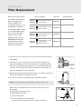
Filters & Filter Change Indicators
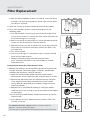
Filter Replacement
Extended Non-Use
24
24
25
29
31
32
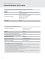
TECHNICAL INFORMATION
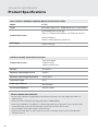
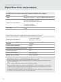
Product Specifications
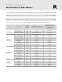
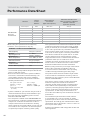
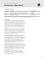
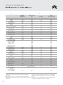
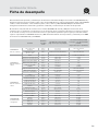
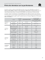
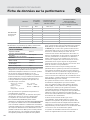
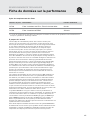
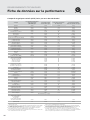
Performance Data Sheet
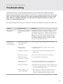
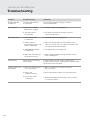
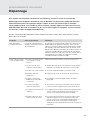
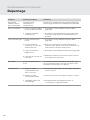
Troubleshooting
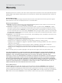
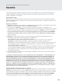
Warranty
Contact
33
67
SPANISH
FRENCH
CAPELLA MANUAL
Contents

1
SAVE THESE INSTRUCTIONS 1
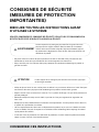
SAFETY INFORMATION
IMPORTANT SAFEGUARDS
READ ALL INSTRUCTIONS BEFORE USING
BE CAREFUL TO KEEP THIS SAFETY INFORMATION. PLEASE READ THIS INFORMATION TO PREVENT
PROPERTY LOSS AND ENSURE SAFETY.
• Never unscrew the filters while the product is in use. This may cause failure due to high water pressure,
or it may cause a water leak.
• Do not install near radiators. This may cause fire, or the product could be damaged, resulting in leakage.
• Use or place the unit on a level area, and do not apply force to the unit. This may cause physical injury
and/or damage to the product that may void your warranty.
• Turn the water supply o at the T-valve if the filter system will not be used for an extended period of time.
• Especially during very cold weather, the water pressure may rise and may cause a water leak.
• Replace the filters according to their scheduled replacement intervals. If one or more of the filters are
exhausted, the purification quality will diminish.
• When replacing the filter or moving the product, do not pull on the water supply hose. The water supply
hose may become detached, damaged, or the quick connection coupling may be weakened.
• If a water leak occurs while using the product, or the area around the product is wet, turn the water
supply valve o immediately.
WARNING
If not observed, serious physical injury or property damage may occur as a result.
Read all the instructions before using or installing the Capella. Never disassemble,
repair, or reconstruct the filter head housing. This may cause the product to fail.
CAUTION If not observed, physical injury or property damage may occur as a result.

SAVE THESE INSTRUCTIONS
2
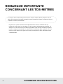
Q: When I use a Total Dissolved Particle (TDS) reader to test my water after it goes through the Capella,
why don't the levels of dissolved particles go down or decrease? I don’t think the product is working.
IMPORTANT NOTE ABOUT
"TDS METERS" AND TESTERS
Generally, Reverse Osmosis systems lower TDS readings by as much as 90% when compared to
tap water readings. This is a normal working range. For example, if your tap water TDS reading
is 100, then a normal TDS reading for the RO filtered water is in the range of 0–10. If the TDS
reading for the RO filtered water is higher than 15% of normal tap water, this indicates it's time for
a filter change, including RO membrane.

3
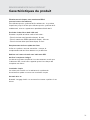
PRODUCT INFORMATION
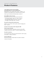
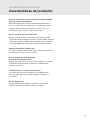
Product Features
Three-Stage Filtration Featuring E2RO
(Eco-Ecient Reverse Osmosis) Membrane
More ecient than traditional RO systems: Capella is up
to 20 times more ecient than conventional RO systems,
featuring a wastewater to filtered water ratio of 1:1.
6 to 24 Month Filter Lifespan
Simplified maintenance and low cost of operation:
• 1st Stage Activated Carbon Plus Filter: 6 months
• 2nd Stage E2RO Membrane Filter: 24 months
• 3rd Stage Carbon Block Filter: 6 months
Easy Quick Change Filter Replacement
Special “twist and seal” filter system makes changing your
filters a breeze.
Chrome Air Gap Faucet with Integrated LED
Filter Change Indicator
Air gap faucet prevents backflow, and the intuitive LED
indicator reminds you when it’s time to change your filters.
Easy DIY Installation
Pre-installed faucet tubing and “quick-connect” water supply
connections simplify installation.
One Year Warranty
Backed by Brondell’s commitment to superior customer
service and support.

4
PRODUCT INFORMATION
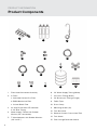
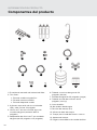
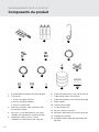
Product Components
7 8
6
1
5
4
2 3
9 10 11
12
13
14
15
1. Filter Head Connector Assembly
2. 3 Filters:
a. Activated Carbon Plus Filter
b. E2RO Membrane Filter
c. Carbon Block Filter
3. Air Gap Faucet with LED Indicator
& 1/4" Blue Tubing
4. Water Supply T-Valve with Rubber
Washer (3/8” connection)
5. T-Valve Adapters with Rubber Washers
(3/8” to 1/2”)
6. 1/4” Water Supply Tubing (White)
7. 3/8” Drain Tubing (Black)
8. 1/4" Brine Input Tubing (Orange)
9. Teflon Tape
10. Drain Clamp
11. Mounting Screws (2x)
12. Tank Ball Valve
13. Reverse Osmosis Pressurized Tank
14. Tank Stand
15. Filter Change Reminder Sticker

5
PRODUCT INFORMATION
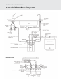
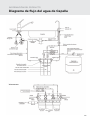
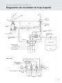
Capella Waterflow Diagram
Backside View
Auto Shuto Valve

6
PRODUCT INFORMATION
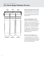
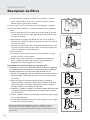
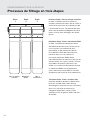
The Three-Stage Filtration Process
Stage One: Activated Carbon Plus Filter
The Activated Carbon Plus filter reduces
particulate materials such as sand, rust,
and fine particles from the water supply.
This first stage also acts as a pre-filter
protecting and extending the life of the
following filters.
Stage Two: E2RO Membrane Filter
The Eco-Ecient Reverse Osmosis
Membrane filter works by pushing water
through a semi-permeable membrane,
thereby separating water molecules from
contaminants in tap water. The powerful
E2RO Membrane significantly reduces
pollutants such as heavy metals, cysts,
fluoride, arsenic, industrial chemicals,
and more. With its unique flow structure,
the E2RO Membrane also utilizes less
feed water and is more ecient than
traditional RO filters.
Stage Three: Carbon Block Filter
The final stage in the filtration process,
the Carbon Block filter further reduces
any lingering water contaminants such as
chlorine and volatile organic compounds
(VOCs), improving the overall taste and
odor of the dispensed water.
Stage
One
Activated Carbon
Plus Filter
E2RO
Membrane
Carbon
Block Filter
Stage
Two
Stage
Three

7
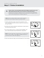
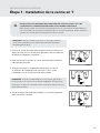
DO NOT INSTALL THE FILTER HEAD CONNECTION ASSEMBLY FURTHER THAN 12 FEET
AWAY FROM EITHER THE WATER SUPPLY VALVE OR THE INDICATOR FAUCET.
Avoid unnecessary slack in the supply hoses when connecting to the water supply, Filter
Head Connection Assembly, or Indicator Faucet. Do not install in direct sunlight or a place
where it will be directly exposed to freezing temperatures.
PRODUCT INSTALLATION
Step 1: T-Valve Installation
NOTE: If the water supply valve is larger than the ⁄” connection on the
T-valve, use the included ⁄” Valve Adapters with Rubber Washers to
connect the T-valve and the water supply hose.
1. Close the cold-water supply valve. Place a bucket or similar
item underneath the valve to catch any water that may spill out
during installation.
2. Unscrew the hose that connects the cold-water supply valve to
the existing tap water faucet.
3. Ensure the rubber washer is inside the T-Valve Adapter, and
then screw the adapter onto the cold-water supply valve.
4. Screw the cold-water supply hose to the top of the T-valve closed.
NOTE: Be sure to install the T-Valve on the cold water supply line.
Running hot water through the Capella will damage the filters.
Step 4
Step 3
Step 1

8
NOTE: If drilling a new hole is required for
the faucet installation, please consult a
professional. Brondell will not be liable for
any damages, including those to the sink or
countertop, due to installation of the faucet
or drilling a hole. Please find answers to
Frequently Asked Questions (FAQs) and
installation videos on brondell.com.
Before Installation
You will need an existing faucet hole at least
1-inch in diameter in the sink or countertop
to install the supplied filtered water faucet.
You may also replace an existing kitchen
sprayer, soap dispenser, or plug already on the
countertop or sink.
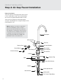
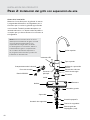
PRODUCT INSTALLATION
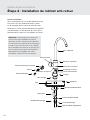
Step 2: Air Gap Faucet Installation
O-Ring
Hole
Locking Nut
Small Split Washer
Large Split Washer
Top Spout
Lock Washer
Spacer
Counter Top
Escutcheon
Air Gap Window
Top Cap
Brine Input
Main Body
1/4" Faucet Tube (Blue)
LED Indicator
Battery Seat
Circuit Board
CR2032 Battery
Drain Output

9
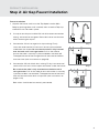
PRODUCT INSTALLATION
Step 2: Air Gap Faucet Installation
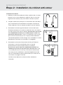
Faucet Installation
1. Unpack the faucet, and insert the Top Spout into the Main
Body by pushing down until inserted, then screw the Top Cap
clockwise until secured in place.
2. Cut zip tie on the pre-installed 1/4-inch blue water connection
tubing, and unroll to straighten. Be careful not to cut the tube
when removing the zip tie.
3. Connect the 1/4-inch orange brine input tubing. Firmly
insert one end into the 1/4-inch brass brine input connector
underneath the faucet. Be sure that the tube is fully inserted
over the barb until it can’t go further. Pull on the tube to
ensure the tube is securely in place and does not come o.
The opposite end of the orange tube will connect to the flow
restrictor later (see instructions on page 16).
4. Connect the 3/8-inch black drain tubing. Firmly insert one end
into the 3/8-inch brass drain output connector under the faucet.
Be sure that the tube is fully inserted over the barb until it
can’t go further. Pull on the tube to ensure the tube is securely
in place and does not come o. The opposite end of the black
tube will connect to the drain clamp later (see instructions on
pages 11-12).
Both tubes should now be securely connected.
Step 4
Step 3
Step 1

10
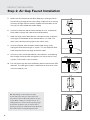
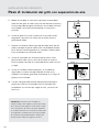
5. Attach the Escutcheon to the Main Body by inserting the blue
faucet tubing, orange brine input tubing, and black drain tubing
(3 tubes) through the Escutcheon. Slide the Escutcheon all the
way up until connected to the Main Body.
6. Install the faucet on top of the countertop or sink, and feed all
three tubes through the hole to the cabinet below.
7. Slide the large, metal Split Washer around the tubes and metal
shaft against the bottom of the countertop or sink hole. The
open split should be facing against the metal shaft.
8. Install the Spacer with the open-ended hole facing up by
sliding the blue tube through as shown. This will keep the blue
tube separate from the orange and black tubes.
9. Install the small, metal Split Washer, Lock Washer, and Locking
Nut through the blue tube and tighten until the faucet is firmly
in place. The faucet is now installed.
10. Pull the plastic tab out from the Battery Seat to activate the LED
Indicator. The LED light will blink red once then blue once, then
it will be ready for use.
TIP: Depending on the amount of space
underneath your sink, you may need to cut
and shorten some of the tubing based on your
needs. When cutting, use sharp scissors or a
cutting knife for a clean cut. The opening edge
of the tube should be even and clean. If the
opening is frayed or crimped, this may aect the
flow of the water running through the tube.
Step 6
Step 7
Step 8
Step 9
Step 5
PG 10, STEP 5
PRODUCT INSTALLATION
Step 2: Air Gap Faucet Installation

11
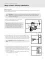
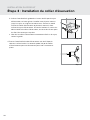
PRODUCT INSTALLATION
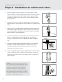
Step 3: Drain Clamp Installation
WARNING: This step may require drilling into the existing drain pipe. Please seek
professional help when completing this step, and always wear safety protection
including safety goggles!
1. Locate a suitable area on the sink drain pipe
to install the provided drain clamp.
NOTE: Select a location for the drain hole based
on the design of the plumbing. It should be installed
above the trap and on the vertical or horizontal
tail piece. Locate the drain connection away from
the garbage disposal. See example to the right.
DO NOT drill all the way through the pipe.
2. You will need to drill a 3/8-inch hole in the drain pipe to install
the drain clamp. Use a 1/4-inch drill bit, and carefully drill a pilot
hole in the drain pipe. Use a 3/8-inch drill bit to enlarge the hole.
Clean the debris from the pipe and the hole before continuing.
3. Find the half of the drain clamp with the hole in its center. Take
the foam gasket piece included with the hardware pack and
remove the adhesive backing. Align the foam gasket hole to the
hole on the drain clamp, and stick the adhesive to the inner wall
of the drain clamp half.
a. Insert a screwdriver, straw, or pencil through the hole on the
drain saddle to use as a guide.
MOUNT
DRAIN VALVE
HERE
Step 3a
Step 2
Step 1
Mount Drain
Clamp Here
Before Installation
You will need to have these tools (not included) for the following installation: 1) drill, 2) 1/4-inch
drill bit, and 3) 3/8-inch drill bit
Garbage
Disposal

12
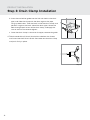
b. Insert the end of the guide into the 3/8-inch hole in the drain
pipe, and slide the clamp with the foam against the pipe,
lining up both holes. Take the back half of the drain clamp and
position it against the back side of the drain pipe. Screw the
bolts through both halves of the drain clamp, and apply the
nuts to secure. Do not over-tighten.
c. Once the drain clamp is secure on the pipe, remove the guide.
4. Take the end of the 3/8-inch black drain tube from the faucet,
and insert into the 3/8-inch Quick Connector on the drain clamp
and push firmly in place.
Step 4
Step 3b
PRODUCT INSTALLATION
Step 3: Drain Clamp Installation

13
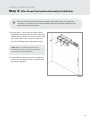
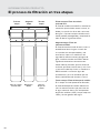
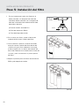
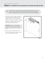
PRODUCT INSTALLATION
Step 4: Filter Head Connection Assembly Installation
NOTE: Before you mount the Connection
Assembly, it may be a good idea to practice
inserting and removing the filters.
1. Using a pencil, mark where the Filter Head
Connection Assembly will be mounted to the
sidewall of the cabinet (at least 14 inches from
the cabinet floor). Use a level to make sure
that the Assembly will be mounted straight.
2. Insert the two mounting screws through the
holes in the Assembly frame, and screw into
the cabinet sidewall.
Step 2
Be sure to install the Filter Head Connection Assembly so that the top of the
assembly is at least 14 inches from the floor of the sink cabinet. Otherwise, the
filters will not install correctly.

14
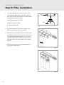
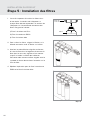
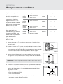
PRODUCT INSTALLATION
Step 5: Filter Installation
Step 3
Step 4
1. It is very important to install the filters in the
correct order. Match the same color label on
each filter to the color label on the Filter Head
Connection from left to right:
1) Activated Carbon Plus Filter
2) E2RO Membrane Filter
3) Carbon Block Filter
2. To insert the filters, line up the arrow on the
filter head with the arrow on the filter.
3. With the top and bottom arrows lined up, push
the top of the filter into the housing and turn to
the right until the filter will not turn any more.
The filter head arrow should now be lined up
with the “circle” icon and notch on the top of
the filter.
4. Repeat the process for the E2RO Membrane
and Carbon Block filters.
Step 2
Filter
Head
Filter

15
Connector
Housing
Step a
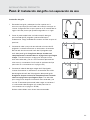
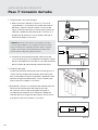
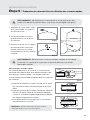
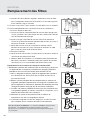
PRODUCT INSTALLATION
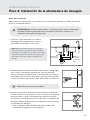
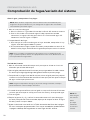
Step 6: Water Storage Tank Prep/Using "Quick Connectors"
1. Apply Teflon tape around the
threaded outlet on top of the
water storage tank.
2. Screw the Tank Ball Valve tightly
to the top of the tank.
3. Place the tank on the tank stand
with the valve upright, and
position it underneath the sink
next to the system assembly.
WARNING: DO NOT tamper with the air valve cap on the front of the water
storage tank. It has been preset at 6psi.
WARNING: DO NOT hold the ball valve to lift or carry the tank. Personal injury or
property damage may result if the valve breaks o.
Tube
Collet
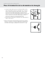
NOTE: Visit brondell.com for our Quick Connect
Tutorial Video.
Using "Quick Connectors"
Tube connections on the T-valve, Filter Head Connection
Assembly, and Indicator Faucet are all of the “Quick
Connect” variety. The steps below illustrate how to
connect and disconnect the tubes from these connectors.
a. Push the tube into the Collet. The collet is a collar
that provides a secure fit for the Tube and prevents
water leaks.
b. Push the tube in until it stops. The tube will
be secure and resistant to tugs or pulls. The
collet will be rigid and raised slightly from the
Connector Housing.
c. To disconnect the tube, push down and hold the
collet first, and then pull the tube out gently.
Step 1
Step 2 Step 3
Step c
Step b
Stand
Air
Pressure
Valve

16
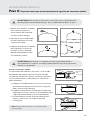
PRODUCT INSTALLATION
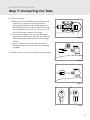
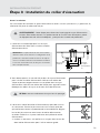
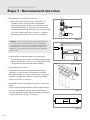
Step 7: Connecting the Tube
1. Water Supply Connection
a. Measure the distance from your T-valve to where
you have installed the filter head assembly, and cut
the white, Water Supply Tubing. Insert one end of
the tubing firmly into the Quick Connect fitting on
the open side of the T-valve. Be sure to push in all
the way, and ensure the tubing is not bent or kinked.
TIP: When cutting the Water Supply Tubing, use sharp
scissors or a cutting knife for a clean cut. The opening
edge of the tube should be even and clean. If the opening
is frayed or crimped, this may aect the flow of the water
running through the tube.
b. Connect the opposite end of the white Water Supply
Tubing into the 90° Quick Connect elbow labeled
“Inlet” located on the left side of the Filter Head
Connector Assembly.
2. Faucet Connection
Connect the open end of the Blue Tubing from the
Faucet to the Filter Head Connector Assembly “Outlet”
by inserting the Tube into the Quick Connect on the
right side. Be sure to push in all the way, and ensure
the tubing is not bent or kinked.
3. Brine Input to Flow Restrictor Connection
Take the opposite end of the 1/4" orange brine input
tube from the faucet, and firmly insert into the Quick
Connect on the Flow Restrictor. Be sure to push in all
the way and ensure the tubing is not bent or kinked.
Step 1a
Step 1b
FLOW
150
Step 3
Inlet
Outlet
Shut-o Valve
Assembly
Step 2
Inlet

17
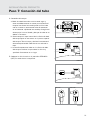
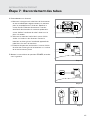
PRODUCT INSTALLATION
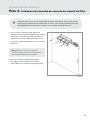
Step 7: Connecting the Tube
Step 4a
Step 4b
Step 4c
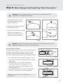
4. Tank Connection
a. Measure out the white Water Supply Tubing, and
carefully cut a piece for connecting the tank.
Locate the Shut-o Valve Assembly. Insert one
end of the tubing firmly into the Quick Connect on
the assembly. Be sure to push in all the way, and
ensure the tubing is not bent or kinked.
b. Unscrew the side cap from the Tank Ball Valve
located on top of the tank. Take the cap and firmly
slide the opposite end of the white tube through
the cap.
c. Firmly insert the tube into the Tank Ball Valve.
Slide the cap over the valve, and securely tighten
into place.
5. Position the blue valve in the OFF position facing left.
Step 5
On O

18
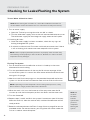
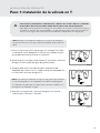
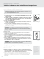
Turn on Water & Check for Leaks
NOTE: Before turning the cold water on, review the installation instructions to
ensure that the T-valve and water hoses are connected correctly and securely.
NOTE: Do
not drink
the water
from the
system until
you have
completed
flushing the
system.
PREPARING FOR USE
Checking for Leaks/Flushing the System
NOTE: Failure to properly install this product or to properly check for leaks may
cause damage to the property. In these instances, Brondell, Inc. will not be held
responsible for any damages.
1. Turn on water supply
a. Open the T-valve by turning the valve arm 90° as shown.
b. Turn the cold-water supply valve at the wall counterclockwise to turn on.
The cold-water supply will then begin to supply water to the Capella.
2. Checking for leaks
a. Once the water supply has been turned on, check for any signs of
leaking throughout the system.
b. If no leaks are found, wait 5 minutes and check one more time. If there
is still no leaking, then continue to next step to flush the system.
Flushing The System
1. Turn on the blue tank shut-o valve so that it is lined up in the same
direction of the tank tubing.
2. Turn the provided faucet on all the way for 10 minutes to purge all the
air out of the system. It is normal for some water to flow out of the faucet
during this first purge.
3. After the initial 10-minute purge, turn the provided faucet o and let the
system run for 90 minutes to allow the water tank to fill for the first time.
4. When the tank is full, turn the faucet on all the way once more for 10
minutes (or until the tank empties) to flush the filters and the water tank.
5. Turn the faucet o.
6. Repeat steps 3 and 4 and flush the system 2 more times (total 3 flushes).
After the last flush, allow the tank to refill, and then filtered water will be
ready to drink.
7. Record installation date on the Filter Change Chart on page 21 or on the
provided sticker. For conveninence, you may place the sticker under the
sink or in another accessible place.
Step 1
On
NOTE: Depending on water temperature and incoming water pressure, it may
take a shorter or longer period of time for the tank to fill.
Step 1
On
La page est en cours de chargement...
La page est en cours de chargement...
La page est en cours de chargement...
La page est en cours de chargement...
La page est en cours de chargement...
La page est en cours de chargement...
La page est en cours de chargement...
La page est en cours de chargement...
La page est en cours de chargement...
La page est en cours de chargement...
La page est en cours de chargement...
La page est en cours de chargement...
La page est en cours de chargement...
La page est en cours de chargement...
La page est en cours de chargement...
La page est en cours de chargement...
La page est en cours de chargement...
La page est en cours de chargement...
La page est en cours de chargement...
La page est en cours de chargement...
La page est en cours de chargement...
La page est en cours de chargement...
La page est en cours de chargement...
La page est en cours de chargement...
La page est en cours de chargement...
La page est en cours de chargement...
La page est en cours de chargement...
La page est en cours de chargement...
La page est en cours de chargement...
La page est en cours de chargement...
La page est en cours de chargement...
La page est en cours de chargement...
La page est en cours de chargement...
La page est en cours de chargement...
La page est en cours de chargement...
La page est en cours de chargement...
La page est en cours de chargement...
La page est en cours de chargement...
La page est en cours de chargement...
La page est en cours de chargement...
La page est en cours de chargement...
La page est en cours de chargement...
La page est en cours de chargement...
La page est en cours de chargement...
La page est en cours de chargement...
La page est en cours de chargement...
La page est en cours de chargement...
La page est en cours de chargement...
La page est en cours de chargement...
La page est en cours de chargement...
La page est en cours de chargement...
La page est en cours de chargement...
La page est en cours de chargement...
La page est en cours de chargement...
La page est en cours de chargement...
La page est en cours de chargement...
La page est en cours de chargement...
La page est en cours de chargement...
La page est en cours de chargement...
La page est en cours de chargement...
La page est en cours de chargement...
La page est en cours de chargement...
La page est en cours de chargement...
La page est en cours de chargement...
La page est en cours de chargement...
La page est en cours de chargement...
La page est en cours de chargement...
La page est en cours de chargement...
La page est en cours de chargement...
La page est en cours de chargement...
La page est en cours de chargement...
La page est en cours de chargement...
La page est en cours de chargement...
La page est en cours de chargement...
La page est en cours de chargement...
La page est en cours de chargement...
La page est en cours de chargement...
La page est en cours de chargement...
La page est en cours de chargement...
La page est en cours de chargement...
La page est en cours de chargement...
La page est en cours de chargement...
La page est en cours de chargement...
La page est en cours de chargement...
-
 1
1
-
 2
2
-
 3
3
-
 4
4
-
 5
5
-
 6
6
-
 7
7
-
 8
8
-
 9
9
-
 10
10
-
 11
11
-
 12
12
-
 13
13
-
 14
14
-
 15
15
-
 16
16
-
 17
17
-
 18
18
-
 19
19
-
 20
20
-
 21
21
-
 22
22
-
 23
23
-
 24
24
-
 25
25
-
 26
26
-
 27
27
-
 28
28
-
 29
29
-
 30
30
-
 31
31
-
 32
32
-
 33
33
-
 34
34
-
 35
35
-
 36
36
-
 37
37
-
 38
38
-
 39
39
-
 40
40
-
 41
41
-
 42
42
-
 43
43
-
 44
44
-
 45
45
-
 46
46
-
 47
47
-
 48
48
-
 49
49
-
 50
50
-
 51
51
-
 52
52
-
 53
53
-
 54
54
-
 55
55
-
 56
56
-
 57
57
-
 58
58
-
 59
59
-
 60
60
-
 61
61
-
 62
62
-
 63
63
-
 64
64
-
 65
65
-
 66
66
-
 67
67
-
 68
68
-
 69
69
-
 70
70
-
 71
71
-
 72
72
-
 73
73
-
 74
74
-
 75
75
-
 76
76
-
 77
77
-
 78
78
-
 79
79
-
 80
80
-
 81
81
-
 82
82
-
 83
83
-
 84
84
-
 85
85
-
 86
86
-
 87
87
-
 88
88
-
 89
89
-
 90
90
-
 91
91
-
 92
92
-
 93
93
-
 94
94
-
 95
95
-
 96
96
-
 97
97
-
 98
98
-
 99
99
-
 100
100
-
 101
101
-
 102
102
-
 103
103
-
 104
104


brondell RF-50 Le manuel du propriétaire
- Taper
- Le manuel du propriétaire
- Ce manuel convient également à
dans d''autres langues
- English: brondell RF-50 Owner's manual
- español: brondell RF-50 El manual del propietario