GE GE30L08BAM Le manuel du propriétaire
- Catégorie
- Chauffe-eau
- Taper
- Le manuel du propriétaire

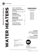
Write the model and serial
numbers here:
Model # _________________
Serial # _________________
You can find them on the rating
label on the front side of your
water heater.
GE is a trademark of the General Electric Company. Manufactured under trademark license.
OWNER’S MANUAL
WATER HEATERS
Electric Residential
49-50336 Rev. 1 06-20 GEA
GE Branded Thermostat Control
Models with Top or Side Water
Connections
SAFETY INFORMATION .........3
OPERATING INSTRUCTIONS ....6
CARE AND CLEANING ...........9
INSTALLATION
INSTRUCTIONS ..................13
TROUBLESHOOTING TIPS ......14
REPLACEMENT PARTS .........15
WIRING DIAGRAM ...............16
LIMITED WARRANTY ...........17
CONSUMER SUPPORT ..........18
ESPAÑOL
Para consultar una version en
español de este manual de
instrucciones, visite nuestro sitio de
internet GEAppliances.com.
FRANÇAIS
Pour une version français de
ce manuel d’utilisation, veuillez
visiter notre site web à l’adresse
GEAppliances.com.
See http://info.nsf.org/Certified/Lead_
Content/ for specific model listing

2 49-50336 Rev. 1
THANK YOU FOR MAKING GE APPLIANCES A PART OF YOUR HOME.
Whether you grew up with GE Appliances, or this is your first, we’re happy to have you in the family.
We take pride in the craftsmanship, innovation and design that goes into every GE Appliances
product, and we think you will too. Among other things, registration of your appliance ensures that we
can deliver important product information and warranty details when you need them.
Register your GE appliance now online. Helpful websites and phone numbers are available in the
Consumer Support section of this Owner’s Manual. You may also mail in the pre-printed registration
card included in the packing material.

49-50336 Rev. 1 3
READ AND SAVE THESE INSTRUCTIONS
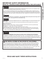
IMPORTANT SAFETY INFORMATION
READ ALL INSTRUCTIONS BEFORE USING THE APPLIANCE
SAFETY INFORMATION
WARNING
For your safety, the information in this manual must be followed to minimize the risk of fire or explosion, electric
shock, or to prevent property damage, personal injury, or loss of life.
Be sure to read and understand the entire Owner’ s Manual before attempting to install or operate this water
heater. It may save you time and cost. Pay particular attention to the Safety Instructions. Failure to follow these
warnings could result in serious bodily injury or death. Should you have problems understanding the instructions
in this manual, or have any questions, STOP and get help from a qualified service technician or the local electric
utility.
CAUTION
Risk of Fire - Hydrogen gas can be produced in a hot water system served by this water heater that has
not been used for a long period of time (generally two weeks or more). HYDROGEN GAS IS EXTREMELY
FLAMMABLE!! To dissipate such gas and to reduce risk of injury, it is recommended that the hot water faucet be
opened for several minutes at the kitchen sink before using any electrical appliance connected to the hot water
system. If hydrogen is present, there will be an unusual sound such as air escaping through the pipe as the water
begins to flow. Do not smoke or use an open flame near the faucet at the time it is open.
WARNING
Risk of Fire - DO NOT store or use gasoline or other flammable vapors and liquids in the vicinity of this or
any other appliance. Keep rags and other combustibles away.
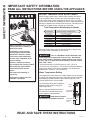
FOR INSTALLATIONS IN THE STATE OF CALIFORNIA
California Law requires that residential water heaters must be braced, anchored or strapped to resist falling
or horizontal displacement due to earthquake motions. For residential water heaters up to 52 gallon (236.4 L)
capacity, a brochure with generic earthquake bracing instructions can be obtained from: Office of the State
Architect, 400 P Street, Sacramento, CA 95814 or you may call 916.324.5315 or ask a water heater dealer.
Applicable local codes shall always govern installation. For residential water heaters of a capacity greater than
52 gallons (236.4 L) consult the local building jurisdiction for acceptable bracing procedures.
WARNING
If the water heater has been subjected to flood, fire, or physical damage, turn off power and water to the
water heater.
Do not operate the water heater again until it has been thoroughly checked by qualified service personnel.
Safety Precautions
A. Do turn off power to water heater if it has been subjected to overheating, fire, flood or physical damage.
B. Do Not turn on water heater unless it is filled with water.
C. Do Not turn on water heater if cold water supply shut-off valve is closed.
NOTE: Flammable vapors may be drawn by air currents from surrounding areas to the water heater.
D. If there is any difficulty in understanding or following the Operating Instructions or the Care and Cleaning
section, it is recommended that a qualified person or serviceman perform the work.

4 49-50336 Rev. 1
SAFETY INFORMATION
READ AND SAVE THESE INSTRUCTIONS
IMPORTANT SAFETY INFORMATION
READ ALL INSTRUCTIONS BEFORE USING THE APPLIANCE
Time/Temperature Relationship in Scalds
Temperature Time to Produce a Serious Burn
120°F (49°C) More than 5 minutes
125°F (52°C) 1-1/2 to 2 minutes
130°F (54°C) About 30 seconds
135°F (57°C) About 10 seconds
140°F (60°C) Less than 5 seconds
145°F (63°C) Less than 3 seconds
150°F (66°C) About 1-1/2 seconds
155°F (68°C) About 1 second
Table courtesy of Shriners Burn Institute
!
Water temperature over 125°F can
cause severe burns instantly or
death from scalds.
Temperature control settings
usually approximate tap water
temperature. However, factors
could cause water temperature
to reach 160°F regardless of the
control settings.
Children, disabled and elderly
are at highest risk of being scalded.
See instruction manual before
setting temperature at water
heater.
Feel water before bathing or
showering.
Temperature limiting valves are
available; see manual.
The chart shown above may be used as a guide in determining
the proper water temperature for your home.
DANGER
There is a Hot Water SCALD Potential if the
water temperature thermostat is set too high. Households
with small children, disabled or elderly persons may require
a 120°F (49°C) or lower thermostat setting to prevent contact
with “HOT” water.
Thermostat has been set at the factory to 120°F (49°C) to
reduce the risk of scald injury. This is the recommended starting
temperature setting, but it can be adjusted to any temperature
between 90°F and 150°F (32°C and 66°C).
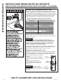
Water Temperature Setting
The temperature of the water in the water heater can be regulated
by setting the temperature dial of the adjustable surface mounted
thermostat(s) located behind the jacket access panel(s). Dual
element heaters have 2 thermostats.
The illustration shows the temperature
adjustment dial used for setting the
water temperature.
Refer to the Operating Instructions in
this manual for detailed instructions in
how to adjust the thermostat(s).
DANGER
Hotter water increases
the Potential for Hot Water SCALDS.
WATER TEMPERATURE ADJUSTMENT
Safety, energy conservation, and hot water capacity are factors
to be considered when selecting the water temperature setting
of the water heater. Water temperatures above 125°F can cause
severe burns or death from scalding. Be sure to read and follow the
warnings outlined on the label pictured to the left. This label is also
located on the water heater near the top of the tank.
R
E
S
E
T
R
E
S
E
T
90°F150°F
125°F
TURN OFF
POWER
BEFORE
SERVICING
Reset
button
Thermostat
dial pointer
Thermostat
protective
cover

49-50336 Rev. 1 5
IMPORTANT SAFETY INFORMATION
READ ALL INSTRUCTIONS BEFORE USING THE APPLIANCE
SAFETY CONTROLS
The water heater is equipped with a combination
thermostat and high limit Energy-Cut-Off control (ECO)
that is located above the heating element in contact
with the tank surface. If for any reason the water
temperature becomes excessively high, the high limit
control (ECO) breaks the power circuit to the heating
element. Once the control opens, it must be reset
manually. Resetting of the high limit control should be
done by a qualified service technician.
CAUTION
The cause of the high temperature
condition must be investigated by a qualified
service technician and corrective action must be
taken before placing the water heater in service
again.
To reset the temperature-limiting control:
1. Turn off the power to the water heater.
2. Remove the jacket access panel(s) and insulation.
The thermostat protective cover should not be
removed.
3. Press the red RESET button.
4. Replace the insulation and jacket access panel(s)
before turning on the power to the water heater.
5. Ensure water heater is operating properly after
resetting the ECO.
READ AND SAVE THESE INSTRUCTIONS
SAFETY INFORMATION

6 49-50336 Rev. 1
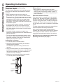
Operating Instructions
Water Heater Capacity and Increasing
Temperature Setpoint:
The water heater temperature setting strongly impacts
the amount of usable hot water available for showers
and baths.
• Safety regulations require a factory setting no
greater than 125°F (52°C) for all new water heaters.
Therefore, if your old water heater was set to a hotter
temperature than your new water heater with a factory
set setpoint of 120°F (49°C), the new water heater
may seem to provide lower capacity than your old
water heater. This can be corrected by increasing the
temperature setpoint.
• If more hot water capacity is desired, increasing the
temperature from 120°F to 135°F (49°C to 57°C)
will enable the same tank of hot water to last about
25% longer because less hot water is mixed in at the
shower or faucet.
• Increasing the water temperature setpoint may
improve the cleaning performance of dishwashers and
washing machines.
• The user can adjust the temperature setting to meet
their needs. Always read and understand the safety
instructions contained in the owner’s manual before
adjusting the temperature setpoint.
If adjustment is necessary...
1. Turn off the power to the water heater.
2. Remove the jacket access panel(s) and insulation
exposing the thermostat(s).
The thermostat protective cover(s) should not be
removed.
3. Using a small screwdriver, set the thermostat(s) dial
pointer(s) to the desired temperature. Adjust the upper
and lower thermostats to the same temperature to
maximize hot water availability.
4. Replace the insulation and jacket access panel(s).
Turn on the power to the water heater.
Mixing Valves
• Mixing valves for reducing point-of-use water
temperature by mixing hot and cold water in branch
water lines are commercially available. Contact a
licensed plumber or the local plumbing authority for
further information.
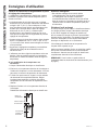
Extended Shutdown Periods
If the water heater is to remain idle for an extended
period of time, the power and water to the appliance
should be turned off and the water heater drained to
conserve energy and prevent a buildup of dangerous
hydrogen gas. This unit has no power button, power
can only be shut off at the circuit breaker or disconnect
switch.
The water heater and piping should be drained if they
might be subjected to freezing temperatures.
After a long shutdown period, the water heater’s
operation and controls should be checked by qualified
service personnel. Make certain the water heater is
completely filled again before placing it in operation.
NOTE: Refer to the Hydrogen Gas Caution in the
Operating Instructions (see page 3).
OPERATING INSTRUCTIONS
R
E
S
E
T
R
E
S
E
T
90°F150°F
125°F
TURN OFF
POWER
BEFORE
SERVICING
Reset
button
Thermostat
dial pointer
Thermostat
protective
cover

49-50336 Rev. 1 7
Routine Preventive Maintenance
DANGER
Risk of Scald - Before manually
operating the relief valve, make certain no one will
be exposed to the danger of coming in contact with
the hot water released by the valve. The water may
be hot enough to create a scald hazard. The water
should be released into a suitable drain to prevent
injury or property damage.
NOTE: If the temperature and pressure-relief valve
on the hot water heater discharges periodically, this
may be due to thermal expansion in a closed water
system. Contact the water supplier or your plumbing
contractor on how to correct this. Do not plug the
relief valve outlet.
Properly maintained, your water heater will provide years
of dependable trouble-free service. It is suggested that
the following annual preventive maintenance program be
established.
1. Inspect Temperature & Pressure Relief Valve.
2. Inspect heating elements, ECO, and wiring to each.
3. Drain and Flush the water heater tank.
4. Anode rod must be removed and inspected.
Temperature and Pressure-Relief Valve:
Once a year, it is recommended to lift and release the
lever handle on the temperature and pressure-relief
valve, located on the front-right side of the water heater,
to make certain the valve operates freely. Allow several
gallons to flush through the discharge line to an open
drain.
Heating Elements and ECO:
Once a year, it is recommended to inspect the heating
elements, ECO, and wiring to each. Inspection should
be completed by service personnel qualified in electrical
appliance repair.
Most electrical appliances, even when new, make some
sound when in operation. If the hissing or singing sound
level increases excessively, the electric heating element
may require cleaning. Contact a qualified installer or
plumber for inspection.
Draining and Flushing the Water Heater
CAUTION
Risk of Shock - Shut off power to
the water heater before draining water.
DANGER
Risk of Scald - Before manually
operating the relief valve, make certain no one will
be exposed to the hot water released by the valve.
The water drained from the tank may be hot enough
to present a scald hazard and should be directed to
a suitable drain to prevent injury or damage.
A water heater’s tank can act as a settling basin for
solids suspended in the water. It is therefore not
uncommon for hard water deposits to accumulate in the
bottom of the tank. To clean the tank of these deposits, it
is recommended to drain and flush the water heater tank
once a year. To drain the water heater, follow these
steps:
1. Turn off power to the unit. The electric heating
elements will become damaged if operated without
water.
2. Attach a garden hose to the drain valve located at the
bottom of the unit and direct that hose to a drain.
3. Turn off the cold water supply.
4. Admit air to the tank by opening a hot water faucet or
lifting the handle on the relief valve.
5. Open the drain valve.
Flushing the Tank:
1. Follow steps above to drain the water heater.
2. Once the water heater is empty, with the drain valve
open and garden hose attached to the drain valve,
turn on the cold water supply.
3. Allow several gallons to flush through the drain valve
and hose to an open drain.
4. Turn off the water supply and allow any water
remaining in the tank to drain.
5. Repeat steps 3 and 4 until water runs clear.
6. Close the drain valve and fill the tank before returning
power to the unit. The tank is full when water runs out
of a nearby open hot water faucet.
Flushing should be done with an empty tank to promote
additional removal of sediment.
NOTE: See page 11 for product schematic.
CARE AND CLEANING
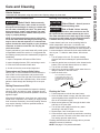
Care and Cleaning
Exterior Surfaces
Hand wash with damp cloth, using only warm water. Wipe dry using a dry, clean cloth.
Use a flat blade screwdriver
to turn brass drain valve or an
adjustable open-end wrench to
turn black stem on plastic drain
valve.
Straight Brass
Drain Valve

8 49-50336 Rev. 1
CARE AND CLEANING
Anode Rod
Anode rods are designed and installed to protect and
extend the life of residential water storage tanks.
The anode rod must be removed from the water heater’s
tank and inspected annually, and replaced when more
than 6” (15.2 cm) of core wire is exposed at either end of
the rod.* NOTE: Artificially softened water will cause the
anode rod to consume more rapidly.
Due to shock hazard and to prevent accidental water
leaks, this inspection should be done by a qualified
servicer or plumber, and requires that the electric power
and cold water supply be turned off before servicing the
anode rod.
NOTICE: Do not remove the anode rod from the water
heater’s tank except for inspection and/or replacement,
as operation with the anode rod removed will shorten
the life of the glass-lined tank and will void warranty
coverage.
Some areas have water conditions that may cause
an odor to develop in the water heater. Special alloy
replacement rods are available to address the condition.
*NOTE: Failure to replace the anode rod when
consumed voids the warranty for the tank. Warranty
coverage for all other components remains intact,
and is unaffected by this maintenance requirement.
The replacement anode rod, and the inspection for
consumption are not covered by warranty.
Care and Cleaning
Routine Preventative Maintenance

49-50336 Rev. 1 9
CARE AND CLEANING
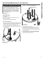
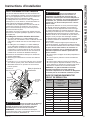
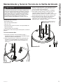
Anode Rod Maintenance and Service
Tools needed:
• Flat Head Screwdriver
• Socket/Torque Wrench
• 1
1
/16” Socket
• Pipe Joint Compound or Pipe Thread Sealant Tape
• Anode Rod, if needed
* See page 18 for part ordering instructions
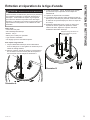
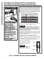
To service the Anode Rod:
1. Disconnect power, shut off the water supply, drain the
water lines of the home. Drain one or two gallons from
the water heater through the lower drain valve.
2. Remove anode cap and foam insulation in hole with
flat head screwdriver to expose anode fitting as shown
in Illustration A.
3. Using a 1
1
/16” socket, unscrew the anode rod, then lift
out to inspect as shown in Illustration B.
4. Inspect and replace if necessary.
5. To install the anode rod, seal the threads with pipe
joint compound or pipe thread sealant tape, thread
into the port and using the torque wrench tighten to 50
± 5 ft-lbs of torque.
6. Turn water supply on, open a tap to remove any air
in plumbing system, inspect for leaks, then replace
anode cap and turn the power on.
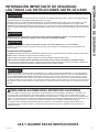
CAUTION - IMPORTANT SAFETY NOTICE
This information is intended for use by individuals
possessing adequate background of electrical,
electronic and mechanical experience. Any attempt
to repair a major appliance may result in personal
injury and property damage. The manufacturer or
seller cannot be responsible for the interpretation
of this information, nor can it assume any liability in
connection with its use.
Illustration A
Illustration B
Replace Anode Rod if
more than 6” of core wire
is exposed.

10 49-50336 Rev. 1
Installation Instructions
INSTALLATION INSTRUCTIONS
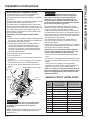
The location chosen for the water heater must take
into consideration the following:
LOCAL INSTALLATION
REGULATIONS
This water heater must be installed in accordance
with these instructions, local codes, utility codes,
utility company requirements or, in the absence of
local codes, the latest edition of the National Electrical
Code. It is available from some local libraries or
can be purchased from the National Fire Prevention
Association, Batterymarch park, Quincy, MA 02169 as
booklet ANSI/NFPA 70.
POWER REQUIREMENTS
Check the markings on the rating plate of the water
heater to be certain the power supply corresponds
to the water heater requirements. NOTE: 208V
installations may experience lower performance.
LOCATION
The water heater and water lines should be protected
from freezing temperatures and high-corrosive
atmospheres. Do not install the water heater in
outdoor, unprotected areas.
Locate the water heater in a clean dry area as near as
practical to the area of greatest heated water demand.
Long uninsulated hot water lines can waste energy
and water. Unit must be installed in a level location.
If required, add shims under base of unit to level for
proper operation.
NOTE: This unit is designed for any common indoor
installation.
Servicing the water heater requires proper installation
such that front panels can be removed to permit
inspection and servicing. Reference installation
instructions found in this manual.
Moving the water heater or other appliances to provide
service to the water heater is not covered under
warranty.
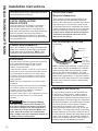
CAUTION
Risk of Property Damage -
The water heater should not be located in an
area where leakage of the tank or connections
will result in damage to the area adjacent to it
or to lower floors of the structure. Where such
areas cannot be avoided, it is recommended
that a suitable catch pan, adequately drained, be
installed under the water heater.
LOCATION (Cont).
Required clearances:
There must be sufficient clearance between any
object and the top, rear and sides of the water
heater in the event service is needed. The controls
and drain at front of unit must have clear access
for operation and service. Installations that require
minimal clearance on the sides or rear of the water
heater for earthquake straps are also acceptable.
In these cases, additional clearance should be
provided on the opposite side of the unit to
allow for service access.
CATCH PAN INSTALLATION
(If required)
NOTE: Auxiliary catch pan MUST conform to local
codes. Catch Pan Kits are available from the store
where the water heater was purchased, a builder
store or any water heater distributor. The catch
pan should be 2” (5.1 cm) minimum larger than the
Water Heater base diameter. To prevent corrosion
and improve Drain Valve access it is recommended
that the water heater be placed on spacers inside
the catch pan.
Relief Valve
Drain Line
Catch Pan
Catch Pan
Drain (piped to
suitable drain)
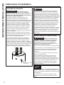
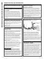
THERMAL EXPANSION
If a check valve is present on the inlet water line,
it will create a “closed system.” Heating water in
a closed system creates an increase in pressure
within the water system because the pressure is not
able to dissipate in the main supply line. Referred to
as “thermal expansion”, the rapid pressure increase
can cause the relief valve to operate (releasing
water) during each heating cycle, potentially
causing premature failure to the valve or even the
water heater. The suggested method of controlling
thermal expansion is to install an expansion tank in
the cold water line between the water heater and the
check valve as shown in the following illustrations.
Contact your installing contractor, water supplier, or
plumbing inspector for additional information.

49-50336 Rev. 1 11
Installation Instructions
INSTALLATION INSTRUCTIONS
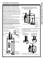
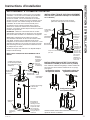
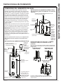
WATER SUPPLY CONNECTIONS
Refer to the illustration below for recommended
installation. The HOT and COLD water connections
are clearly marked and are ¾” NPT on all models.
When connecting to the inlet/outlet ports, the use of ¾”
female NPT tapered thread fittings with use of thread
sealant is recommended. The installation of unions is
recommended on the hot and cold water connections
so that the water heater may be easily disconnected
for servicing if necessary. Piping should be routed to
allow anode rod removal.
NOTE: Install a shut-off valve in the cold water line
near the water heater. This will enable easier service
or maintenance of the unit later.
IMPORTANT: Do not apply heat to the HOT or
COLD water connections. If sweat connections
are used, sweat tubing to adapter before fitting
the adapter to the cold water connections on
heater. Any heat applied to the hot or cold water
connection will permanently damage the internal
plastic lining in these ports.
Install a vacuum relief valve and/or anti-siphon device
when required by local jurisdictions.
TYPICAL TOP CONNECT INSTALLATION
TYPICAL SIDE CONNECT INSTALLATION
(Otherwise same as Top Connect Installation)
HOT AND COLD PIPE INSULATION INSTALLATION
(if supplied with product)
For increased energy efficiency, some water heaters
have been supplied with two 24” sections of pipe
insulation.
Please install the insulation, according to the
illustrations above, that best meets your requirements.
Hot water
outlet to
fixtures
Shut-off valve
To cold
water
supply
Unions
Thermal
expansion
tank
(Install per
manuf.
instructions),
if required
Relief Valve
discharge within
6” of floor and no
closer than 2 times
the pipe diameter
per local code
Temperature &
Pressure Relief Valve
Conduit to Electrical
Junction Box (use only
copper conductors)
(Model appearance
may vary)
Drain valve
To cold
water
supply
Relief Valve
discharge
within 6” of
floor and no
closer than
2 times the
pipe diameter
per local
code
Conduit to Electrical Junction Box
(use only copper conductors)
(Model appearance may vary)
Drain valve
Hot water
outlet to
fixtures
Shut-off
valve
Temperature &
Pressure Relief
Valve
Typical vertical
piping arrangement
Typical horizontal
piping arrangement
Typical side piping
arrangement
Unions

12 49-50336 Rev. 1
Installation Instructions
INSTALLATION INSTRUCTIONS
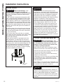
TO FILL THE WATER HEATER
WARNING
Risk of Unit Damage - The
tank must be full of water before heater is turned
on. The water heater warranty does not cover
damage or failure resulting from operation with
an empty or partially empty tank.
Make certain the drain valve is completely closed.
Open the shut-off valve in the cold water supply line.
Open each hot water faucet slowly to allow the air to
vent from the water heater and piping.
A steady flow of water from the hot water faucet(s)
indicates a full water heater.
Condensation can form on the tank and fittings when
it is first filled with water. Condensation may also
occur with a heavy water draw and very cold inlet
water temperature.
This condition is not unusual and will disappear once
water is heated. If condition persists, examine fittings
for potential leaks and repair, as required.
NOTICE
Do not mis-wire electrical connections. 240VAC or
208VAC must be applied across L1 and L2 wires as
shown in ‘Water heater junction box’ illustration.
If a 4-conductor wire is supplied to the water heater,
cap the neutral, and connect the remaining wires as
illustrated.
RELIEF VALVE
WARNING
Risk of Unit Damage - The
pressure rating of the relief valve must not
exceed 150 PSI (1.03 MPa), the maximum working
pressure of the water heater as marked on the
rating plate.
A new combination temperature and pressure-relief
valve, complying with the Standard for Relief Valves
and Automatic Gas Shut-Off Devices for Hot Water
Supply Systems, ANSI Z21.22, is supplied and must
remain installed in the opening provided and marked
for this purpose on the water heater. No valve of any
type should be installed between the relief valve and
the tank. Local codes shall govern the installation of
relief valves.
The BTUH rating of the relief valve must not be less
than the input rating of the water heater as indicated
on the rating label located on the front of the heater
(1 watt=3.412 BTUH).
Connect the outlet of the relief valve to a suitable
open drain so that the discharge water cannot contact
live electrical parts or persons and to eliminate
potential water damage.
Piping used should be of a type approved for hot
water distribution. The discharge line must be no
smaller than the outlet of the valve and must pitch
downward from the valve to allow complete drainage
(by gravity) of the relief valve and discharge line. The
end of the discharge line should not be threaded or
concealed and should be protected from freezing.
No valve of any type, restriction or reducer coupling
should be installed in the discharge line.
CAUTION
To reduce the risk of excessive pressures and
temperatures in this water heater, install temperature
and pressure protective equipment required by local
codes and no less than a combination temperature
and pressure relief valve certified by a nationally
recognized testing laboratory that maintains periodic
inspection of production of listed equipment or
materials, as meeting the requirements for Relief
Valves and Automatic Gas Shutoff Devices for Hot
Water Supply Systems, ANSI Z21.22. This valve
must be marked with a maximum set pressure not
to exceed the marked maximum working pressure
of the water heater. Install the valve into an opening
provided and marked for this purpose in the water
heater, and orient it or provide tubing so that any
discharge from the valve exits only within 6 inches
above, or at any distance below, the structural floor,
and does not contact any live electrical part. The
discharge opening must not be blocked or reduced in
size under any circumstances.
Relief Valve
Insulation

49-50336 Rev. 1 13
Installation Instructions
INSTALLATION INSTRUCTIONS
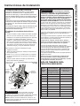
ELECTRICAL CONNECTIONS
A separate branch circuit with copper conductors,
overcurrent protective device and suitable
disconnecting means must be provided by a qualified
electrician.
All wiring must conform to local codes or latest edition
of National Electrical Code ANSI/NFPA 70.
The water heater is completely wired to the junction
box at the top of the water heater. An opening for 1/2”
electrical fitting is provided for field wiring connections.
The voltage requirements and wattage load for the
water heater are specified on the rating label on the
front of the water heater.
The branch circuit wiring should include
either:
1. Metallic conduit or metallic sheathed cable approved
for use as a grounding conductor and installed with
fittings approved for the purpose.
2. Nonmetallic sheathed cable, metallic conduit or
metallic sheathed cable not approved for use
as a ground conductor shall include a separate
conductor for grounding. It should be attached to
the ground terminals of the water heater and the
electrical distribution box.
To connect power to the water heater:
1. Turn the power off.
2. Remove the screw/screws holding the junction box
top cover.
3. Install L1 to L1, L2 to L2 and ground wire onto the
fixed junction box cover, per illustration below.
4. Reconnect all screws attaching the junction box
covers.
WARNING
Risk of fire or electrical shock.
Ensure both junction box covers and ground
screws are securely fastened for proper
grounding.
NOTE: Install electric connections according to local
codes or latest edition of National Electrical Code
ANSI/NFPA 70.
WARNING
Proper ground connection is
essential. The presence of water in the piping
and water heater does not provide sufficient
conduction for a ground. Nonmetallic piping,
dielectric unions, flexible connectors, etc., can
cause the water heater to be electrically isolated.
Do not disconnect factory ground.
The manufacturer’s warranty does not cover any
damage or defect caused by installation, attachment
or use of any type of energy-saving or other
unapproved devices (other than those authorized by
the manufacturer) into, onto or in conjunction with the
water heater. The use of unauthorized energy-saving
devices may shorten the life of the water heater and
may endanger life and property.
The manufacturer disclaims any responsibility for
such loss or injury resulting from the use of such
unauthorized devices.
If local codes require external application of insulation
blanket kits, the manufacturer’s instructions included
with the kit must be carefully followed.
Application of any external insulation, blankets
or water pipe insulation to this water heater will
require careful attention to the following:
• Do not cover the temperature and pressure-relief
valve.
• Do not cover access panels to the heating elements.
• Do not cover the electrical junction box of the water
heater.
• Do not cover the operating or warning labels
attached to the water heater or attempt to relocate
them on the exterior of the insulation blanket.
NOTE: This guide recommends minimum branch
circuit sizing based on the National Electric Code.
Refer to wiring diagrams in this manual for field
wiring connections.
BRANCH CIRCUIT SIZING GUIDE
Total
Water
Heater
Wattage
Recommended Over-
Current Protection
(fuse or circuit breaker
amperage rating)
Copper Wire Size AWG
Basedon N.E.C. Table
310-16 (167°F/75°C.)
@240V 208-240V 208-240V
3,000 20 12
4,000 25 10
4,500 25 10
5,000 30 10
5,500 30 10
6,000 35 8
8,000 45 8
9,000 50 8
10,000 – –
11,000 – –
12,000 – –
Junction
Box Cover
Junction
Box Cover
House
Ground
(Green)
Water Heater Junction Box
L1
(Black)
Factory Ground
L2
(Red)

14 49-50336 Rev. 1
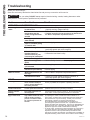
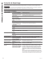
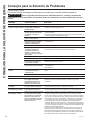
Troubleshooting
Before you call for service....
Save time and money! Review the chart below first and you may not need to call for service.
CAUTION
For your safety, DO NOT attempt repair of electrical wiring, controls, heating elements or other
safety devices. Refer repairs to qualified service personnel.
Problem Possible Causes What To do
OPERATION AND PERFORMANCE
Not enough or no hot
water
Water temperature may
be set too low
• See the Water Temperature Adjustment and Water Heater
Capacity sections. (Pages 4 and 6)
Cold water inlet
temperature may be
colder during the winter
months
• This is normal. The colder inlet water takes longer to heat.
• Consider increasing the set temperature as described in
the Water Temperature Adjustment section.
Leaking or open hot
water faucets
• Make sure all faucets are closed.
Long runs of exposed
pipe, or hot water piping
on outside wall
• Insulate piping.
Dip tube damaged • Contact your local installer, plumbing contractor, or
previously agreed upon service agency.
A fuse is blown, circuit
breaker tripped, or
electric service to your
home may be interrupted
• Replace fuse or reset circuit breaker.
• Contact the local electric utility.
Inadequate wiring • See the Installation Instructions.
Manual reset high limit
(ECO)
•
See the Safety Controls section, see page 5.
Water Connections to
unit reversed
• Correct piping connections.
Recirculating System
Interference (if installed)
• Check flow rate is not set too high.
• Insulate piping
Water is too hot Water temperature is set
too high
• See the Water Temperature Adjustment section.
Thermostat has failed
• Contact your local installer, plumbing contractor, or
previously agreed upon service agency.
OTHER
Rumbling noise Water conditions in your
home caused a buildup of
scale or mineral deposits on
the heating elements
• Remove and clean the heating elements. This should only be
done by a qualified service person or plumbing contractor.
Water dripping down the
outside of the heater
Hot/Cold water connections
or other parts have loosened
•
Tighten the loose connections. This should only be done by a
qualified service person or plumbing contractor.
Relief valve producing
popping sound or
draining
Pressure buildup caused
by thermal expansion to a
closed system
• This is an unacceptable condition and must be corrected. See
Thermal Expansion section on page 12. Do not plug the relief
valve outlet. Contact a plumbing contractor to correct this.
Hot water has a rotten
egg or sulfur smell
Certain water supplies with
high sulfate content will react
with the anode rod that is
present in all water heaters
for corrosion protection of
the tank
• The odor can be reduced or eliminated in most water heaters
by replacing the anode rod with less-active material rod. In
some cases, an added step of chlorinating the water heater and
all hot water lines may be necessary, contact your local water
professional or plumber for options and instructions.
Go to GEAppliances.com/waterheater for information on
purchasing this replacement anode rod. A qualified servicer or
plumber should do this replacement. Use of a non-GE Appliances
approved anode rod, or operating the water heater without a GE
Appliances approved anode rod will VOID the warranty.
• In certain cases, increasing the tank temperature to 140°F (60°C)
can reduce this odor issue. Reference the Water Temperature
Adjustment section of the Important Safety Information of this
manual for procedure and dangers of scalding water. Installation of
temperature limiting valves can be used to reduce risk of scalding.
TROUBLESHOOTING

49-50336 Rev. 1 15
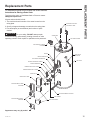
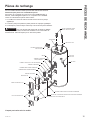
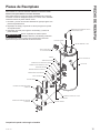
Replacement Parts
REPLACEMENT PARTS
WATER INLET/OUTLET
PIPE & HEAT TRAP
DIP TUBE & GASKET
ANODE ROD
BADGE
UPPER THERMOSTAT
CLIP SPRING THERMOSTAT
HEATING ELEMENT & GASKET
LOWER THERMOSTAT
DRAIN VALVE
INSULATION LARGE
COVER ELEMENT LARGE
& SCREWS
COVER ELEMENT SMALL
& SCREWS
INSULATION SMALL
HEATING ELEMENT & GASKET
CLIP SPRING
BARRIER DIELECTRIC UPPER
BARRIER DIELECTRIC LOWER
JUNCTION BOX COVERS
& SCREWS
INSULATION
T&P VALVE
T&P VALVE
Appearance may vary by model.
For standard thermostat control models with double elements.
Instructions for Placing a Parts Order
To place orders using a Visa/MasterCard or Discover contact
GEApplianceparts.com.
All parts orders should include:
1. The model and serial number of the water heater from the
rating plate.
2. Specify voltage and wattage as marked on the rating plate.
3. Part description (as noted below) and number of parts
desired.
CAUTION
For your safety, DO NOT attempt repair
of electrical wiring, thermostat(s), heating elements or other
operating controls. Refer repairs to qualified service personnel.

16 49-50336 Rev. 1
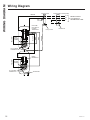
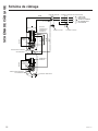
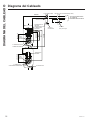
Wiring Diagram
WIRING DIAGRAM
YELLOW
BLUE
BLUE
BLACK
LOWER
HEATING
ELEMENT
UPPER
HEATING
ELEMENT
HIGH TEMP
LIMIT SWITCH
& UPPER
THERMOSTAT
LOWER
THERMOSTAT
JUNCTION BOX
BRANCH CIRCUIT
TO ELECTRICAL
DISTRIBUTION PANEL
GREEN
BLACK
YELLOW
RED
TO WRAPPER
TO CLIP SPING
THERMOSTAT
TO CLIP SPING
THERMOSTAT
L1
L2
G
JUNCTION BOX COVER (FIXED)
Factory Ground
House Ground
Wire
Connectors
GREEN
13
24
14
2
1
2
1
2
3
4
4
1
2
1
2

49-50336 Rev. 1 17
Staple your receipt here. Proof of the original purchase
date is needed to obtain service under the warranty.
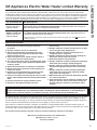
GE Appliances Electric Water Heater Limited Warranty
What Is Not Covered:
Ŷ 6HUYLFHWULSVWR\RXUKRPHWRWHDFK\RXKRZWRXVH
the product.
Ŷ ,PSURSHULQVWDOODWLRQGHOLYHU\RUPDLQWHQDQFH
Ŷ 5HSODFHPHQWSDUWVVKLSSLQJDQGKDQGOLQJDQGFRVWWR
remove defective part or tank after the first year limited
warranty are NOT covered.
Ŷ )DLOXUHRIWKHSURGXFWLILWLVDEXVHGPLVXVHGDOWHUHGRU
used for other than the intended purpose.
Ŷ 8VHRIWKLVSURGXFWZKHUHZDWHULVPLFURELRORJLFDOO\XQVDIH
or of unknown quality, without adequate disinfection before
or after the system.
Ŷ 5HSODFHPHQWRIKRXVHIXVHVRUUHVHWWLQJRIFLUFXLWEUHDNHUV
Ŷ 'DPDJHWRWKHSURGXFWFDXVHGE\DFFLGHQWOLJKWQLQJILUH
flood or acts of God.
Ŷ ,QFLGHQWDORUFRQVHTXHQWLDOGDPDJHFDXVHGE\SRVVLEOH
defects with this appliance, its installation or repair.
Ŷ 3URGXFWQRWDFFHVVLEOHWRSURYLGHUHTXLUHGVHUYLFH
in a safe
manner. Attic installation must have flooring and accessible
stairs.
Ŷ ,ISURGXFWUHPRYHGIURPRULJLQDOLQVWDOODWLRQORFDWLRQ
Ŷ ,ISURGXFWRURWKHUDSSOLDQFHPXVWEHPRYHGIRU
service access.
Ŷ 'DPDJHPDOIXQFWLRQRUIDLOXUHFDXVHGE\WKHXVHRIUHSDLU
service not approved by GE Appliances.
Ŷ 'DPDJHPDOIXQFWLRQRUIDLOXUHFDXVHGE\WKHXVHRI
unapproved parts or components.
Ŷ 'DPDJHPDOIXQFWLRQRUIDLOXUHFDXVHGE\RSHUDWLQJWKH
water heater with the anode rod removed.
Ŷ $QRGH5RGLQVSHFWLRQDQGUHSODFHPHQW
Ŷ 'DPDJHPDOIXQFWLRQRUIDLOXUHUHVXOWLQJIURPRSHUDWLQJWKH
water heater with an empty or partially empty tank.
Ŷ 'DPDJHPDOIXQFWLRQRUIDLOXUHFDXVHGE\VXEMHFWLQJWKH
tank to pressure greater than those shown on the rating
label.
Ŷ 'DPDJHPDOIXQFWLRQRUIDLOXUHFDXVHGE\RSHUDWLQJWKH
water heater with electrical voltage outside the voltage
range listed on the rating label.
Ŷ :DWHUKHDWHUIDLOXUHGXHWRWKHZDWHUKHDWHUEHLQJRSHUDWHG
in a corrosive atmosphere.
Ŷ ,IWKLVZDWHUKHDWHULVXVHGIRURWKHUWKDQUHVLGHQWLDOSULYDWH
family use, labor will not be covered under warranty, and
the parts warranty is reduced to 1 year from the date of
purchase.
EXCLUSION OF IMPLIED WARRANTIES—Your sole and exclusive remedy is product repair as provided
in this Limited Warranty. Any implied warranties, including the implied warranties of merchantability or
fitness for a particular purpose, are limited to one year or the shortest period allowed by law.
LIMITED WARRANTY
This limited warranty is extended to the original purchaser and any succeeding owner for products purchased for home use within
the USA. If the product is located in an area where service by a GE Appliances Authorized Servicer is not available, you may
be responsible for a trip charge or you may be required to bring the product to an Authorized GE Appliances Service location for
service. In Alaska, the limited warranty excludes the cost of shipping or service calls to your home.
Some states do not allow the exclusion or limitation of incidental or consequential damages. This limited warranty gives you
specific legal rights, and you may also have other rights which vary from state to state. To know what your legal rights are, consult
your local or state consumer affairs office or your state’s Attorney General.
For product purchased outside of the US, contact your dealer for Warranty and Service information.
Warrantor for Products Purchased in the United States:
GE Appliances, a Haier company
Louisville, KY 40225
All warranty service is provided by our Factory Service Centers, or an authorized Customer Care® technician. To schedule service
for your GE water heater call GE Water Heaters at 1-800-943-8186. Please have your serial number and your model number
available when calling for service. Servicing your appliance may require the use of the onboard data port for diagnostics. This gives
a GE Appliances factory service technician the ability to quickly diagnose any issues with your appliance and helps GE Appliances
improve its products by providing GE Appliances with information on your appliance. If you do not want your appliance data to be
sent to GE Appliances, please advise your technician not to submit the data to GE Appliances at the time of service
For The Period Of: We Will Replace:
One Year
From the date of the
original purchase
Any factory specified part of the water heater which fails due to a defect in materials or
workmanship. During this limited one-year warranty, we will also provide, free of charge, all
labor and related service to replace the defective part.
Second through
Eighth or Tenth Year
From the date of the
original purchase
Any part of the Water Heater which fails due to a defect in materials or workmanship. During
this limited second through the end of the warranty period, labor and related service to
replace the defective part are not included.
*Warranty is based on the 6th and 7th digit of model number located on rating plate (e.g.: GE50T08BAM has a part
warranty of 8 years).

18 49-50336 Rev. 1
Printed in ChinaPrinted in China
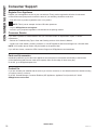
Consumer Support
CONSUMER SUPPORT
Register Your Appliance
Register your new appliance on-line at your convenience! Timely product registration will allow for enhanced
communication and prompt service under the terms of your warranty, should the need arise.
• Scan QR Code on product registration card, or on product.
NOTE: This is just an example of what a QR code represents.
• Or go to GEAppliances.com/register
• Or mail in your pre-printed registration card included in the packing material
Consumer Service
If you have a question or need assistance with your new water heater on adjustments, repairs, or routine
maintenance:
• Review the Troubleshooting Tips or Care and Cleaning sections of this Owner’s Manual.
• Contact your local installer, plumbing contractor, or call GE Appliances Service and Support at 1-800-943-8186.
NOTE: Your installer phone number may be located on the product label.
If you still have issues, contact the GEA Customer Support at GEAppliances.com/waterheater
Parts and Accessories
Individuals qualified to service their own appliances can have parts or accessories sent directly to their homes.
(VISA, MasterCard and Discover cards are accepted). Order on-line today 24 hours every day.
In the US, go to GEApplianceparts.com
Contact Us
If you are ultimately not satisfied with the service you receive, contact us on our Website with all the details including
your phone number, or write to:
In the US: General Manager, Customer Relations |GE Appliances, Appliance Park |Louisville, KY 40225
GEAppliances.com/contact

Voir http://info.nsf.org/Certified/Lead_
Content/ for specific model listing
Inscrivez les numéros de modèle
et de série ici :
No de modèle ____________
No de série ______________
Vous trouverez ces numéros sur
l’étiquette apposée à l’avant de
votre chauffe-eau.
GE est une marque déposée de General Electric Company. Fabriqué sous licence de marque.
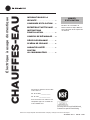
MANUEL
D’UTILISATION
CHAUFFES-EAU
Électrique à usage domestique
49-50336 Rev. 1 06-20 GEA
INFORMATION SUR LA
SÉCURITÉ .........................3
CONSIGNES D’UTILISATION ....6
ENTRETIEN ET NETTOYAGE ....9
INSTRUCTIONS
D’INSTALLATION ................13
CONSEILS DE DÉPANNAGE ....14
PIÈCES DE RECHANGE .........15
SCHÉMA DE CÂBLAGE .........16
GARANTIE LIMITÉE .............17
SOUTIEN
AU CONSOMMATEUR ...........18
Modèles de commande de
thermostat de marque GE avec
raccordements d’eau supérieurs
ou latéraux

2 49-50336 Rev. 1
NOUS VOUS REMERCIONS D’ACCUEILLIR GE APPLIANCES CHEZ VOUS
Que vous ayez grandi avec GE Appliances ou qu’il s’agisse de votre première acquisition, nous
sommes heureux de vous accueillir dans notre famille.
Nous sommes fiers du savoir-faire, de l’innovation et de l’esthétique qui composent chaque appareil
GE Appliances, et nous pensons que vous le serez aussi. Dans cette optique, nous vous rappelons
que l’enregistrement de votre électroménager vous assure la communication de renseignements
importants sur le produit et la garantie lorsque vous en avez besoin.
Enregistrez votre électroménager GE en ligne dès maintenant. Des sites Web et des numéros de
téléphone utiles figurent dans la section Soutien au consommateur de ce manuel d’utilisation. Vous
pouvez aussi poster la fiche de garantie pré-imprimée incluse dans l’emballage.
La page est en cours de chargement...
La page est en cours de chargement...
La page est en cours de chargement...
La page est en cours de chargement...
La page est en cours de chargement...
La page est en cours de chargement...
La page est en cours de chargement...
La page est en cours de chargement...
La page est en cours de chargement...
La page est en cours de chargement...
La page est en cours de chargement...
La page est en cours de chargement...
La page est en cours de chargement...
La page est en cours de chargement...
La page est en cours de chargement...
La page est en cours de chargement...
La page est en cours de chargement...
La page est en cours de chargement...
La page est en cours de chargement...
La page est en cours de chargement...
La page est en cours de chargement...
La page est en cours de chargement...
La page est en cours de chargement...
La page est en cours de chargement...
La page est en cours de chargement...
La page est en cours de chargement...
La page est en cours de chargement...
La page est en cours de chargement...
La page est en cours de chargement...
La page est en cours de chargement...
La page est en cours de chargement...
La page est en cours de chargement...
La page est en cours de chargement...
La page est en cours de chargement...
-
 1
1
-
 2
2
-
 3
3
-
 4
4
-
 5
5
-
 6
6
-
 7
7
-
 8
8
-
 9
9
-
 10
10
-
 11
11
-
 12
12
-
 13
13
-
 14
14
-
 15
15
-
 16
16
-
 17
17
-
 18
18
-
 19
19
-
 20
20
-
 21
21
-
 22
22
-
 23
23
-
 24
24
-
 25
25
-
 26
26
-
 27
27
-
 28
28
-
 29
29
-
 30
30
-
 31
31
-
 32
32
-
 33
33
-
 34
34
-
 35
35
-
 36
36
-
 37
37
-
 38
38
-
 39
39
-
 40
40
-
 41
41
-
 42
42
-
 43
43
-
 44
44
-
 45
45
-
 46
46
-
 47
47
-
 48
48
-
 49
49
-
 50
50
-
 51
51
-
 52
52
-
 53
53
-
 54
54


GE GE30L08BAM Le manuel du propriétaire
- Catégorie
- Chauffe-eau
- Taper
- Le manuel du propriétaire
dans d''autres langues
- English: GE GE30L08BAM Owner's manual
- español: GE GE30L08BAM El manual del propietario
Documents connexes
Autres documents
-
State SGV-82-10TS , SGV-120-10TS Manuel utilisateur
-
Rheem Professional Classic Series: Standard Electric Manuel utilisateur
-
 GE Appliances GE30T12BLM Le manuel du propriétaire
-
Bradford White RE2H50S10 Manuel utilisateur
-
Maytag HRX75XQRSCGA Manuel utilisateur
-
-
A.O. Smith FMD 50 Manuel utilisateur
-
Hotpoint-Ariston GL8Ti Le manuel du propriétaire
-
Rheem PROTECH SP10869PH Mode d'emploi
-
GE Appliances Standard Electronic and Integrated Electronic Mixing Valve Water Heaters Mode d'emploi
