Maytag 23-11-2229N-004 Manuel utilisateur
- Catégorie
- Climatiseurs split-system
- Taper
- Manuel utilisateur

Room Air Conditioners for Double-Hung Windows & Thru the wall installation
Acondicionadores de aire ambientales para ventanas de guillotina y empotrados en la pared
Climatiseurs - Installaton dans un mur ou une fen_tre a guillotine
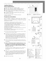
For Future Reference !i I
Write down the model and serial numbers I
The model and serial numbers can be found on the i
/
side of the cabinet near the control panel. Use
these numbers in any correspondence or service
calls concerning your air conditioner.
Para referencia futura
Escriba los numeros del modelo y de la serie
Puede encontrar los n(imeros de modelo y de serie en el
costado de la rejilla del frente decorativo cerca del panel de
control. Use estos nQmeros en cualquier correspondencia o
Ilamada de servicio con relaci6n a su acondicionador de aire.
Pour r_f_rence ult_rieure
Inscrivez les numeros de modele et de serie
Les num6ros de module et de s6rie se trouvent sur le c6t6 de la
grille ddcorative avant, pros du panneau de commande. Utilisez
ces numdros Iors de toute correspondance ou appel au service
apr_s-vente ayant trait _ votre climatiseur.
Model No., Modelo No., N° de modele
Serial No., Numero de serie, N° de serie
Date of Purchase, Fecha de la compra, Date d'achat
For additional questions please call:
1-866-MAYTAG- 1
or e-maih
customerservice@maytagair, com
Keep these instructions for future reference

Important Safety Instructions°°°°°°°°°°°°°°°°°°°°°°°°
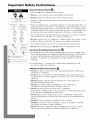
RECOMMENDEDCIRCUIT
WIRESIZES
(As installed per building code) :
PROTECTORSIZE WIREGAUGE
15 AMP #14 MINIMUM
20 AMP #12 MINIMUM
30 AMP #10 MINIMUM
©©
125V 250V
15A 20A
©©
250V 250V
15A 30A
Three- )rong grounding plug.
Do not a ter pug enc.
@Grounded three-prong wall receptacle
Single outlet grounding wall receptacle
A
Electrical Shock Hazard
• Plug unit only into grounded electrical outlet.
• Do not use an extension cord or plug adapter with this unit.
• Do not operate unit with decorative front or filter removed.
• Failure to follow these precautions could result in electrical shock, fire or
personal injury.
• If the air conditioner has a serial plate rating of 115 volts and greater than 7.5
amps it must have its own fuse or circuit breaker, and no other device or unit
should be operated on that fuse or circuit breaker. If the air conditioner has a
serial plate rating of 230 volts it must have its own fuse or circuit breaker, and
no other device or unit should be operated on that fuse or circuit breaker.
• We recommend that a qualified electrician install unit in accordance with the
National Electrical Code and local codes and ordinances.
• Do not operate this air conditioner without proper time delay circuit
protection. Refer to serial plate for proper power supply requirements.
• Use copper conductors of correct wire gauge and protector size only.
• Do not alter cord or plug end. Do not remove warning label on cord.
Important Grounding Requirements
• Air conditioner has a three-prong grounding plug on the power supply cord,
which must be plugged into a properly grounded three-prong wall receptacle
for your protection against possible shock hazard. For models up to and
including 7.5 amperes use a grounding type wall receptacle to match the
cord plug.
• For models above 7.5 amperes use a single outlet grounding type wall
receptacle to match the cord plug.
A
Additional Safety Precautions
• Do not cut, alter or remove any of the expanded polystyrene (white foam)
inside this air conditioner.
• Do not store or use gasoline or other flammable vapors and liquids in the
vicinity of this or any other appliance. The fumes can create a fire hazard or
explosion.
• Do not introduce objects in the air discharge area. This could cause
permanent damage to your unit.
• Do not pour liquids on the air conditioner as this could cause a
malfunction. Use a damp cloth for cleaning your unit.
• Avoid using strong solvents to clean the air conditioner.
• Clean the air conditioner filter every two weeks to avoid overheating caused
by air obstruction. Do not operate without filter.
• Do not obstruct the air intake area of your air conditioner, as this could
cause overheating, thus activating the units security switch and shutting off
the unit
• Do not block air circulation to outside louvers of cabinet.
• Do not block air flow inside with blinds, curtains, or furniture, or outside
with shrubs, enclosures, or other buildings.
• Do not run the air conditioner with an outside protective cover in place.
This could result in mechanical damage within the air conditioner.
2

Installation°°°°°°°°°°°°°°°°°°°°°°°°°°°°°°°°°°°°°°°°°°°°°°°°
Window Requirements:
This air conditioner is factory prepared for installation in standard
double-hung windows with actual opening width of 26 7/8" to 41
5/8" and clear, vertical opening of 15 5/8" minimum from bottom
of sash to sill. Unit can be installed in 23 7/8" wide window, if
cabinet side seals are removed.
Tools Needed
Screwdrivers Ratchet or Driver with 1/4" socket
Carpenter's Level Tape Measure
Fastener Identification
Installation Parts Kit contents:
Item Description
O 1" wood screw
_!_ 5/8" wood screw
O
4
Actual size
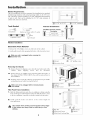
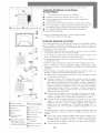
Window Installation
Decorative Front Removal
1. Remove the 3/8" phillips screws on either side of the cabinet
2. Gently pull forward while grasping both sides of the decorative front.
_ ake sure unit is unplugged before removing the
decorative front.
Removing the Chassis
I, Remove the two (2) shipping screws from the rear bottom side of the
cabinet. These shipping screws may be discarded.
2, Remove the two (2) antitheft screws from the bottom front sides of
the cabinet. RETAIN THESE SCREWS, they will be replaced later ill
the installation.
3, Slide the chassis out of the cabinet by grasping the base pall handle
and pulling forward while bracing the top bar.
_ ake sure unit is unplugged before removing chassis
from cabinet.
Filler Panel Frame Installation
I, Slide the filler panel frame onto the air conditioner cabinet using the
tracks on the top bar and bottom bar of the unit. Slide the frame as close
to the air conditioner as possible so that the curtain locks into place.
2, Gently pull the frame out until it is the correct length for
your application.
Use caution when working around exposed sharp edges
of the cabinet and sharp coils to avoid injury or torn
clothing.
3
(_Cabinet (_ 3/8" phillips screw
C) Decorative Front
1_ Shipping Screws (_Chassis
C)Cabinet i_Base pan handle
(_ Anti-theft screws
(_Top Bar (_Bottom Bar
(_ Filler Panel Frame (_Cabinet
1_ Filler Panel Locking Edge

Installation°°°°°°°°°°°°°°°°°°°°°°°°°°°°°°°°°°°°°°°°°°°°°°°°
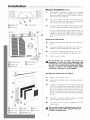
C) Window sill (_) 1" Wood Screw
(_) Bottom Bar
Side View
Window Installation (co.t.)
1 •
Open window, by raising lower window sash, and mark
the center of window sill. Carefully place cabinet in
window and align center hole on the bottom bar with the
center mark on the window sill.
2•
3•
Close lower window sash until it touches behind the top
bar. (Do not release your grip on the cabinet until the
lower window sash is ill its final position).
Attach the cabinet to the window sill by driving one 1" long
wood screw through the bottom bar into the window sill.
.....0
C) Carpenter's Level
C) Window sash
(_ Filler Panel
0 5/8" wood screw
C) Window sill
®
Be sure cabinet maintains an downward pitch. Air
conditioner should slant slightly downward on the
outside as shown by 1/2 a bubble off on a carpenter's
level. This outward pitch prevents water from entering the
room.
Securing the Filler Panels
4. Slide filler panels outward until they touch window sash
tracks.
5•
6•
Secure top of filler panels by driving a 5/8" wood screw
through each top mounting hole into window sash.
Secure bottom of filler panels by driving a 5/8" wood
screw into window sill through each filler panel tab.
7. Install chassis into cabinet.
_ Do not obstruct the air intake area of your air
conditioner, as this could cause overheating, thus
activating the units security switch and shutting off
the unit. Do not block aiflow inside with blinds,
curtains, or furniture. Do not block airflow outside
with shrubs, enclosures, or other buildings.
®
(_ Foam Seal
(_ Lower sash
(_ Filler panel
(_ Molding C)Chassis
® Window Sill (_) Dec front
(_ Anti-Theft screw
Installing the Chassis into the Cabinet
_1. Slide the chassis into the cabinet.
2 • Replace the two antitheft screws at the bottom front sides
of cabinet.
3•
To replace the decorative front, line up the top tabs and
and sides, and gently press into position. Reattach the
screws on both sides of the decorative front. Make sure
the power cord aligns with the power cord slot on the
bottom of the decorative front. Make sure the decorative
front is secure before reconnecting the plug and operating
the unit.
4. Cut plastic foam seal to width of window and install
between upper and lower window sash.
5. Use latex or silicone sealant (not supplied) to fill any
minor openings.
_ Do not drill a hole in the bottom pan. Unit is
designed to operate with approximately 1/2"
of water in bottom pan.
4

®@@@@@@@@@@@@@@@@@@@@@@@@@@@@@@@@@@@@@@@@@@@@@@@@@@@@@@@@@@@
Installing Cabinet in
Minimum Width Window
"1, Remove filler panels on air conditioner cabinet.
2. Refer to steps 1 through 3 of Window Installation instructions.
3. Close window until it touches behind air conditioner top bar.
4. Fasten top bar to window frame using 5/8" washer head screw.
5. If filler is required on sides of air conditioner, cut plastic foam seal
to size and fill both sides.
6. Use silicone or latex sealant (not supplied to fill any minor openings.
7. Install chassis into cabinet.
Consult your authorized dealer or importer for alternative
installation instructions.
Through-the-wall Installation
This air conditioner is designed as a slide-out type chassis, making it
possible to install it through-the-wall in both existing and new
construction. We recommend that this type of installation be performed
with professional assistance.
• IMPORTANT: This appliance must be installed according to all
applicable electrical and building codes and ordinances.
• It is recommended that you have help to install your unit and that you
use proper lifting technique to avoid personal injury.
• It is important that you inspect the condition of the wall where the air
conditioner will be installed.
• Be sure the wall can support the weight of the unit.
• All cabinet louvers MUST BE on the outdoor side of the wall. DO NOT
BLOCK SIDE LOUVERS.
• The cabinet must be installed level from side-to-side and with a
downward tilt from inside to outside.
"1, First remove the Decorative front panel and chassis from the cabinet,
then remove top bar from the cabinet.
2=
Determine the size of the opening for a wood frame by adding 1/8"
to the width and height of the cabinet. Measure height from top of
cabinet to bottom of bar. Add this measurement to the thickness of
wood used to build the frame. This will determine the size of wall
opening needed. Minimum 1" thick lumber is recommended when
building the frame. When determining finish frame thickness, be sure
not to cover side louvers on the cabinet.
:3. Install the finished frame in the wall opening square and level, nail
or screw it securely to the wall and place the cabinet into the framed
wall opening.
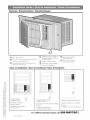
4, Make sure cabinet projects into the roomside of the wall 1 1/4" at
the top and 1 1/2" at the bottom to ensure proper tilt and access to
the anti-theft screw, then fasten cabinet to the frame by drilling
twelve (12) 1" wood screws (not supplied) through the cabinet and
into the frame. (Fig. 1 &2)
If installation is made in a building with brick veneer construction, a
steel angle lintel must be used to support the bricks above the
cabinet.(Fig.3)
5=
Install a 3/4" X 1 1/2" wood filler strip between the bottom bar and
the interior, caulk both top and bottom of this strip. After cabinet is
installed caulk all openings, inside and outside between finish frame
and cabinet to prevent moisture from getting to the interior of the
wall. Use of flashing (driprail) will further prevent water from
dripping inside the wall.
6. Install chassis into cabinet.
5
@
C) Top Bar C) Attach top bar here
Fig. 1
Fig. 2
i:
Fig. 3
C) Wood frame
C) 1" wood screws
C) Cabinet
Q Bottom Bar
C) Interior wall
(_ Decorative Front
(_ Minimum lx6 wood
support (nailed or
screwed to wood
frame)
(_2" Wood frame
C)1 1/2" space
C)1 1/4" space
C)Brick veneer
C)Lintel angle
(_Caulking
(_)Flashing (drip rail)
C)Side louvers
(_Wood filler strip

Operation°°°°°°°°°°°°°°°°°°°°°°°°°°°°°°°°°°°°°°°°°°°°°°°°°°
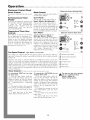
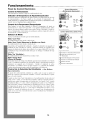
Electronic Control Panel
Power Control
The Power Control turns the unit on and
off.
Set Temperature/Timer
Display
Shows the set temperature when the unit
is in operation and hours when the timer
is being set. THE TEMPERATURE
DISPLAY ONLY SHOWS THE SET
TEMPERATURE, NOT THE ACTUAL
ROOM TEMPERATURE.
Temperature/Timer Hour
Controls
These buttons are used to raise or lower
the set temperature in increments of 1°
from 66°F to 88°F. By depressing both
buttons at once, the display will toggle
between Celsius and Fahrenheit. When
the timer is being set, these buttons are
used to change the hour setting in
increments of 1 from 00 to 24.
Mode Control
A green light will indicate which mode is
currently being utilized.
Cool Mode-
The unit will circulate and cool the air.
Heal; Mode (Heat Models Only) -
The unit will circulate and heat the air.
Heater Safety Feature- When heater is
powered off, low fan will automatically stay
on and run for 60 seconds to ensure the
removal of residual heat, meanwhile, the
Low Fan LED blinks until the low fan stops.
Fan Mode-
The unit will only circulate the air.
Energy Saver Mode -
(The energy saver mode is designed to
operate with Cool mode only). The fan
will switch from the set fan speed to Low
whenever the compressor turns off in
response to the thermostat. When the
compressor cycles back on, the unit will
return to the original fan setting. Speeds
will change automatically as the
temperature in the room changes.
Fan Speed Control - High, Medium, Low and Auto
The settings are adjusted with the Fan Speed Control, each time the button is
depressed it changes the setting. A green light will indicate which setting is currently
being used.
When the Auto feature is selected while the air conditioner is in the Cool or Heat
mode, the fan speeds will change automatically as the temperature in the room
changes. In Cool Mode when the room reaches 7° or more above the set temperature
High Fan will be used, 4 ° or less above the set temperature will use Low fan. In Heat
Mode when the room reaches 7° or more below the set temperature High fan will be
used, 4 ° or less below the set temperature will use Low fan. At all other times the fan
will use Medium fan.
Timer Control (The timer can be set to either turn the unit on or off.)
To automatically START the unit using
the Timer mode:
1. Push the timer button while the
power is OFF. The display will read 00.
Adjust the display to show the desired
number of hours before START-UP using
the Temperature/Timer adjustment
arrows.
2. The display will show the amount of
time, in hours, remaining until START-UP.
3. To exit Timer mode, push the Timer
button.
4. A green light next to the Timer
button indicates that the timer is set.
To automatically SHUT-DOWN the unit
using the Timer mode:
1. Push the timer button while the
power is ON. The display will read 00.
Adjust the display to show the desired
number of hours before SHUT-DOWN
using the Temperature/Timer adjustment
arrows. (The display will automatically
return to the set temperature after 10
seconds.)
2. To display the amount of time left
until SHUT-DOWN, push the Timer
button once.
3. To exit Timer mode, push the Timer
button twice.
4. A green light next to the Timer
button indicates that the timer is set.
Electronic Control (Cooling Only)
• Cool
• Energy Save
• Fan
Built in 7hroe Minute Cooling Delay
Electronic Control (Heat/Cool)
Built in Three Minute Cooling Delay
Temperature/Timer Display
Temperature/Timer Adjustment
Timer On/Off
Fan Speed Control
Mode Control
Power Control
_ he heat from this unit is designed
only as a supplemental heat
source in addition to
regular heating systems.
6

®@@@@@@@@@@@@@@@@@@@@@@@@@@@@@@@@@@@@@@@@@@@@@@@@@@@@@@@@@@@@@@
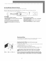
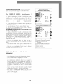
Air Conditioner Remote Control
The functions work the same as your air conditioner's touch controls.
Batteries: Remove the cover on the back of the remote controller and insert the batteries with the
(+) and (-) poles pointing in the proper direction.
0
0
CAUTION
• Use onlyAAA or IEC R03 1.5V batteries.
• Remove the batteries ff the remote controller is not used for
a month or longer.
• Do not attempt to recharge the supplied batteries
• Aft batteries should be replaced at the same time.
• Do not dispose of the batteries in a fire as they may
explode.
AAA ......! i
• Do not mix old and new batteries.
• Do not mix alkaline, standard (carbon- zinc), or rechargeable
(nickle-cadmium) batteries.
• Keep batteries and other objects that could be swallowed
away from young children.
Contact a doctor immediately ff an object is swallowed.
Directing Airflow
Unit is engineered with adjustable louvers to direct discharge airflow. Louvers are
manually adjusted by moving levers ill direction of desired airflow.
Q Filter @ Louvers Q Vent door
Cleaning the Air Filter Clean the filter every two weeks
1. Turn Master Control to OFF.
2. Remove the air filter by opening the air intake panel on the decorative front and
pull it out of the unit.
3. Wash in hot soapy water, rinse and shake dry.
4. Replace the filter, with the front of the filter toward you.
5. To dry the filter thoroughly, run your unit for a few minutes. Remember, only a
clean filter works properly and delivers top efficiency at every setting.
_ ote: Failure to keep air filter clean will result in poor air circulation.
DO NOT operate without filter. This can render the unit inoperative.
Proper use and care of your air conditioner will help ensure longer life of the
unit. It is recommended to annually inspect and clean the coils and condensate
water passages. Expense of annual inspection is the consumer's responsibility.
7

Maintenance°°°°°°°°°°°°°°°°°°°°°°°°°°°°°°°°°°°°°°°°°°°°°°
Service To save tinqe and expense, check the following before calling an authorized service station.
Insufficient Cooling
• Turn Master Control to OFF.
• Shut all windows and doors in room.
• Remove any obstructions from inside and outside louvers.
• Close Vent Door (available on some models).
• Inspect filter and clean if dirty.
• Turn Thermostat and Master Controls to coolest settings.
Under certain conditions the cooling coils directly behind the
filter, may ice up and block the airflow. This is a common
occurrence in air conditioners caused when the outside
temperature drops below 70°F (21°C) while the humidity
remains high. If this happens, simply turn the unit off and allow
the ice to melt, then resume normal operation.
Insufficient Heating- Heating Models Only
• Turn Master Control to OFF.
• Shut all windows and doors in room.
• Remove any obstructions from inside and outside louvers.
• Close Vent.
• Turn Thermostat to Warmer and Master Control to HI HEAT.
Unit Fails to Start
• Turn Master Control to OFF.
• Replug line cord plug into outlet to be sure electrical contact
is being made. (If firm contact is not being made, outlet may
have to be replaced).
• Turn Master Control to HI FAN. If air circulating fan does not
operate, check house circuit breaker (or fuses).
For Models Installed in North America - If Service or Parts are Required First, make the recommended checks. If it appears that
service or parts are still required, see your room air conditioner warranty "How to Obtain Warranty Service or Parts".
For Models Installed Outside North America For room air conditioners purchased for use outside North America, the
manufacturer does not extend any warranty either expressed or implied. Consult your local dealer for any warranty terms
extended by the importer in your country.
Visit www.fedders.com for obtaining serviceable parts beyond your warranty period.
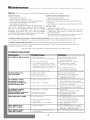
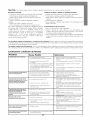
Troubleshooting Guide
Occurrence
Air conditioner will not operate
Air from unit does not
feel cold enough
Air conditioner cooling,
but room is too warm --
ice forming on cooling coil
behind decorative front
Possible Cause
• Wall plug disconnected,
• House fuse blown or circuit breaker tripped.
• Power switch in OFF position.
• Unit accidentally turned off by moving the
thermostat to a higher temperature and then
immediately turned back to a colder position.
• Unit turned off and then on too quickly.
• Thermostat set too low for cooling.
• Selector in FAN position.
• Thermostat set too warm.
• Room temperature below 70°F.
• Outdoor temperature below 70°F.
• Dirty air filter air restricted.
• Thermostat set too cold for nighttime cooling.
Air conditioner cooling, • Dirty air filter air restricted.
but room too warm --
NO ice forming on cooling coil • Thermostat set too warm.
behind decorative front • Fan selector set on LOW
Noise when unit is cooling • Air movement sound.
• Sound of fan hitting water-moisture
removal system.
• Window vibration poor installation.
Water dripping inside • Improper installation.
when unit is cooling
Water dripping outside • Unit removing large quantity of moisture V"
when unit is cooling from humid room.
Solutions
V" Push plug firmly into wall outlet.
Replace fuse with time delay type
or reset circuit breaker.
Turn power switch to ON position.
Wait approximately 3 minutes.
Listen for the compressor to start.
V" If air conditioner is turned off,
wait 3 minutes before restarting.
V" Adjust thermostat to higher setting for cooling.
V" Set selector to COOL position.
V" Set thermostat to colder temperature.
V" Cooling may not occur until room
temperature rises above 70°F.
V" To defrost the coil, set selector to FAN position.
Then, set thermostat to warmer position.
V" Clean filter. See "Cleaning the Air Filter" section.
To defrost, set selector to FAN.
V" To defrost the coil, set selector to FAN position.
Then, set thermostat to a normal position.
V" Clean air filter.
Refer to "Cleaning Air Filter" section.
V" Set thermostat to colder setting.
_ Set fan speed selector to HIGH
for maximum coolin R.
V" The sound of rushing air is normal. If too loud,
turn selector to lower fan setting.
V" This is normal when humidity is high.
Close doors, windows and registers.
V" Refer to installation instructions
check with installer.
V" Tilt air conditioner slightly to the outside to
allow water drainage. Refer to installation
instructions check with installer.
This is normal during excessively humid clays.
8

Warrantyooooooooooooooooooooooooooooooooooooooooooooooooooo
For Models Installed
in North America - If Service
or Parts are Required
First, make the recommended checks. If it appears that service or
parts are still required, see your room air conditioner warranty
"How to Obtain Warranty Service or Parts".
For Models Installed
Outside North America
For room air conditioners purchased for use outside North
America, the manufacturer does not extend any warranty either
expressed or implied. Consult your local dealer for any
warranty terms extended by the importer in your country.
Room Air Conditioner Warranty
(Within the 48 contiguous United States, state of Hawaii,
the District of Columbia, Puerto Rico and Canada)
Full (FiveYear) Parts and Labor Warranty
During the five years after the date of original purchase,
Fedders North America will, through its authorized servicers
and free of charge to the owner or any subsequent user, repair
or replace any parts which are defective in material or
workmanship due to normal use. Ready access to the air
conditioner is the responsibility of the owner.
Note: In the event of any required parts replacement
within the period of this warranty, Fedders North America
replacement parts shall be used and will be warranted
only for the period remaining on the original warranty.
Exceptions
The above warranty does not cover failure to function caused
by damage to the unit while in your possession (other than
damage caused by defect or malfunction), or by its improper
installation, or by unreasonable use of the unit, including
without limitation, failure to provide reasonable and necessary
maintenance or to follow the written Installation and Operating
Instructions. If the unit is put to commercial, business, rental, or
other use or application other than for consumer use, we make
no warranties, express or implied, including but not limited to,
any implied warranty of merchantability or fitness for particular
use or purpose.
THE REMEDIES PROVIDED FOR IN T_tE ABOVE EXPRESS
WARRANTY ARE THE SOLE AND EXCLUSIVE REMEDIES
T_tEREFOR, NO OTHER EXPRESS WARRANTIES ARE MADE.
ALL IMPLIED WARRANTIES, INCLUDING BUT NOT LIMITED
TO ANY IMPLIED WARRANTY OF MERCHANTABILITY OR
FITNESS FOR A PARTICULAR USE OR PURPOSE, ARE
LIMITED IN DURATION TO FIVE YEARS FROM T_tE DATE OF
ORIGINAL PURC_tASE. IN NO EVENT SHALL FEDDERS
NORT_t AMERICA BE LIABLE FOR INDIRECT, INCIDENTAL,
OR CONSEQUENTIAL DAMAGES, EVEN IF ADVISED IN
ADVANCE OF THE POSSIBILITY OF SUCH DAMAGES. NO
WARRANTIES, EXPRESS OR IMPLIED, ARE MADE TO ANY
BUYER UPON RESALE.
Some states do not allow limitations on how long an implied
warranty lasts or do not allow the exclusion or limitation of
incidental or consequential damages, so the above limitations
or exclusions may not apply to you. This warranty gives you
specific legal rights, and you may also have other rights which
may vary from state to state.
No warranties are made for units sold outside of the above
stated areas. Your distributor or final seller may provide a
warranty on units sold outside of these areas.
How to Obtain
Warranty Service or Parts
Service for your room air conditioner will be provided by
CareCo, a division of the manufacturer with authorized
independent CareCo servicers nationwide.
Note: Before calling for service, carefully read the
Installation and Operating Instructions booklet. Then ff
you need service:
1. Call a CareCo authorized servicer and advise them of model
number, serial number, date of purchase and nature of
complaint. Service will be provided during normal working
hours. Contact your dealer for the name of an authorized
servicer if unknown to you.
2. If your dealer is unable to give you the name of a servicer or
if you need other assistance, call the following toll-free
number for the name of an authorized servicer or authorized
parts distributor:
1-866-MAYTAG 1
or you may write:
CareCo, Service Department
415 W. Wabash Ave., P.O.Box 200
Effingham, IL 62401
Proof of Purchase Date
It is the responsibility of the consumer to establish the original
purchase date for warranty purposes. We recommend that a bill
of sale, cancelled check, or some other appropriate payment
record be kept for that purpose.
Maytagis atrademarkoftheMaytagCorporationandis usedunderlicensebyFeddersNorthAmerica,Inc.
9

Instrucciones importantes de seguridad oooooooooooo
Riesgo de Choque Eldctrico
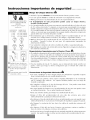
TAMAI_ OS RECOMENDADOS
DE LOS CONDUCTORES DEL
CIRCUITO
(Instaladosseg_nel c6digo de
construcci6n) :
CAPACIDAD DE CALIBRE DE LOS
LOS FUSIBLES CONDUCT()RES
15 AMP #14 COMO MINIM()
20 AMP #12 COMO MINIM()
30 AMP #10 COMO MINIM()
©©
125V 250V
15A 20A
©©
250V 250V
15A 30A
C) Enchufede tres clavijascon
puesta a tierra. No Modifique.
C) Tomacorrienteparaenchufe
de tres clavijas conpuestaa
tierra.
(_ Tomacorrientemural sencillo
con puestaatierra.
• Enchufe el aparato solamente en un tomacorriente el_ctrico puesto a tierra.
• Con este aparato no use un cord6n de extensi6n ni un adaptador de enchufe.
• No haga funcionar el acondicionador de aire sin el panel delantero.
• El incumplimiento de estas precauciones pueden causar un choque el_ctrico,
incendio o lesi6n personal.
• Si el acondicionador de aire tiene una potencia nominal indicada en la placa de serie
de 115 voltios y de mas de 7,5 amperes, es necesario que sea protegido con su propio
fusible o disyuntor y ning0n otro dispositivo debe usar ese mismo disyuntor o fusible.
Si el acondicionador de aire tiene una potencia nominal en la placa de serie de 230
voltios, es necesario que seaprotegido con su propio fusible o disyuntor y ning0n otro
aparato debe usar ese mismo disyuntor o fusible.
• Recomendamos que un electricista calificado instale el acondicionador de aire de
acuerdo con el c6digo el6ctrico nacional y los c6digos y reglamentos locales.
• No haga funcionar este acondicionador de aire sin protecci6n adecuada del circuito
de retardo. Consulte la placa de serie para los requerimientos apropiados de
alimentaci6n el6ctrica.
• Use solamente conductores de cobre y fusibles de calibre y capacidad adecuada.
• No modifique el cord6n ni el enchufe del extremo. No retire la etiqueta de advertencia
del cord6n de alimentaci6n.
A
Requerimientos Importantes para la Puesta a Tierra
• Elcord6n de alimentaci6n del acondicionador de aire tiene un enchufe de tres clavijas
con puesta a tierra el cual debe ser enchufado en un tomacorriente mural puesto a
tierra de tres alv6olos para su protecci6n contra posible riesgo de choque el6ctrico.
Para los modelos de hasta 7,5 amperes o menos, use un tomacorriente mural del tipo
con puesta a tierra que tenga la misma configuraci6n que el enchufe del cord6n de
alimentaci6n.
• Para los modelos de mas de 7,5 amperes, use un tomacorriente mural sencillo con
puesta a tierra que tenga la misma configuraci6n que el enchufe del cord6n de
alimentaci6n.
Precauciones de Seguridad Adicionales
• No corte, modifique ni retire ning0n pedazo de poliestireno expandido (espuma
blanca) situado dentro de este acondicionador de aire.
No guarde ni use gasolina u otros vapores y Ii'quidos inflamables en la vecindad de
este o cualquier otro artefacto. Los vapores emitidos pueden crear un riesgo de
incendio o explosi6n.
No introduzca objetos en el area de descarga del aire. Esto puede causar datio
irreparable a su acondicionador de aire.
No vierta Ii'quidos de limpieza en el acondicionador de aire pues esto puede causar
un malfuncionamiento. Use un patio h0medo para limpiarlo.
Evite usar solventes fuertes para limpiar el acondicionador de aire.
Limpie el filtro del acondicionador de aire cada dos semanas para evitar
sobrecalentamiento causado por obstrucci6n del aire.
No obstruya el area de entrada del aire de su acondicionador, pues esto puede causar
sobrecalentamiento, Io cual activara el interruptor de seguridad y apagara el aparato.
No bloquee la circulaci6n del aire hacia las rejillas de ventilaci6n exteriores del
gabinete.
No obstruya el flujo del aire hacia el interior con persianas, cortinas o muebles o
hacia el exterior con arbustos, recintos u otros edificios.
No haga funcionar el acondicionador de aire teniendo instalada la cubierta protectora
exterior. Esto podffa resultar en datio mecanico dentro del acondicionador de aire.
10

Instalaci6n ooooooooooooooooooooooooooooooooooooooooooooooooo
Dimensiones de la Ventana
Este acondicionador de aire ha sido preparado en la f,_brica para su
instalaci6n en ventanas de guillotina est,_ndares con aberturas de
26,875" a 41,625" de ancho y una abertura vertical de por Io menos
15,625" minimo desde la parte inferior de la hoja m6vil hasta el umbral.
El acondicionador de aire puede ser instalado en ventanas de 24" de
ancho, si se retiran los paneles de sellado laterales del gabinete.
Herramientas Necesarias
Destornilladores Llave de tuercas de trinquete
Nivel Cinta de medir
Identificaci6n deTornillo O _)
Partida Nombre la parte Cantidad _
Tomillo tie madera de 1" 1
Tomillo de madera de 5/8" 4
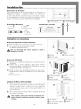
Instalacion en la ventana
Desmontaje del Panel Decorativo Delantero
1. Retire los tornillos que se encuentran a ambos lados del gabinete.
2. Tire suavemente hacia adelante mientras sostiene
los dos lados del frente decorativo.
_ ntes de desmontaje de/ chassis, apague la unidad y
desconecte el enchufe.
Desmontaje del Chasis
1, Retire los dos (2) tomillos de embarque* del costado inferior trasero
del gabinete.
2, Retire los dos (2) tornillos antirrobo de ambos lados delanteros
inferiores del gabinete. CONSERVE ESTOS TORNILLOS, ellos ser,_n
usados posteriormente en la instalaci6n.
3, Deslice el chasis fuera del gabinete sujetando la manija de la
bandeja inferior y tirando hacia adelante a la vez que sujeta el barra
superior.
_Tornillo para chapa de 3/8"
Instalaci6n del Marco del Panel de Relleno
1, Deslice el marco del panel de relleno en el gabinete del
acondicionador de aire usando las guias que se encuentran arriba y
abajo de la unidad. Deslice el marco Io m,_s cerca posible del
acondicionador de aire para que la cortina quede trabada en la
posici6n adecuada.
2, Tire suavemente del marco hasta obtener la Iongitud que necesita
para realizar la instalaci6n.
Tenga cuidado cuando este trabajando alrededor de/as
esqinas afiladas de/gabinete ara evitar heridas o ropas
rasgadas.
11
C) Gabinete C) Delantero Tornillo
(_ Panel Decorativo
C)Tornillos de embarque (_Chasis
C) Gabinete k_Manija de la
(_Tornillos antirrobo* bandeja inferior
(_Barra superior (_ Barra inferior
(_)Marco del Panel de relleno (_ Gabinete
(_ Borde de fijaci6n

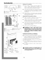
Instalaci6n ooooooooooooooooooooooooooooooooooooooooooooooooo
Instalacion en la Ventana
A_) Umbral de la ventana (_ Tomillo de 1"
_) Barra inferior
C)Nivel C)Tomillo de madera de 5/8"
(_Hoja m6vil de la ventanaC)Umbral de la ventana
(_Panel de relleno
I •
Abra la ventana y marque el centro del umbral de la
ventana. Coloque cuidadosamente el gabinete en la
ventana y alinee el agujero central de la barra inferior con
la marca central trazada en el umbral de la ventana.
2m
3m
Cierre la hoja m6vil inferior de la ventana hasta que toque
el aparato detr,_s de la barra de retdn superior. (No suelte
el gabinete hasta que la hoja m6vil inferior est6 en su
posici6n final).
Instale el gabinete ell el umbral de la ventana colocando un
tomillo de 1" de largo a trav6s de la barra de uni6n inferior
hacia el umbral de la ventana.
Asegureidad de los paneles de relleno
4m
5m
6m
Deslice los paneles de relleno hacia afuera hasta que
toquen los rieles de la hoja m6vil de la ventana.
Asegure la parte superior de los paneles de relleno
instalando tornillos de 5/8" de largo a travds de los agujeros
de montaje superiores hacia el umbral de la ventana.
Asegure la parte inferior de los paneles instalando tornillos
de 5/8" de largo en el umbral de la ventana a travds de las
leng(ietas del panel de relleno.
7. Instale el chasis en el gabinete (p,_gina 15).
No obstruya el _rea de la entrada del aire de su
acondicionador, pues esto puede causar
sobrecalentamiento, Io cual activar_ el interruptor de
seguridad y apagar_ el aparato. No bloquee el flujo
del aire hacia el interior con persianas, cortinas o
muebles o hacia el exterior con arbustos, recintos u
otros edificios.
® ®
C) Espuma de (_ Moldura C) Chasis
relleno (_) Umbral de
I_) Hoja m6vil la ventana (_ Panel
inferior (_ Tornillo decorativo
C) Panel de antirrobo delantero
relleno
Instalaci6n del Chasis en el Gabinete
1. Deslice el chasis hacia el interior del gabinete.
2. Para reinstalar el panel decorativo delantero, col6quelo en
su lugar y empuijelo hacia atr,_s hacia el acondicionador
hasta que entre a presi6n en su lugar. Vuelva a instalar el
tornillo de ret6n detr,_s del panel de entrada del aire.
3. Reinstale los dos tornillos antirrobo en los lados delanteros
inferiores del gabinete.
,4. Corte un relleno de espuma de pl,_stico del ancho de la
ventana e inst,_lelo entre la hoja m6vil superior e inferior de
la ventana.
5. Use compuesto obturador para Ilenar cualquier abertura
m,_s pequeffa.
_ o taladre un agujero en la bandeja inferior. El
acondicionador de aire ha sido diseffado para
funcionar aproximadamente con 1/2" de agua
en la bandeja inferior.
12

®@@@@@@@@@@@@@@@@@@@@@@@@@@@@@@@@@@@@@@@@@@@@@@@@@@@@@@@@@®
T
C) Barra superior ®Tomillo de madera de 5/8"
(_) Marco de madera
@ Tornillos de madera de 1"
(_ Gabinete
(_ Barra inferior
(_ Pared
(_ Panel decorativo
delantero
(_) Soporte de madera de
por Io menos 1 x 6
(_ Marco de madera de
2" por todo el rededor
(Z) Espacio de 1-1/2"
(Z) Espacio de 1-1/4"
(_ Enchapado de ladrillo
1_ Dinte] angular
1_ Material obturador
1_ Guardaaguas
(Vierteaguas)
(clavado o atomillado ('_ Rejillas de ventilacion
ell el marco de madera)<" "
1_ relleno de madera
Instalaci6n del Gabinete en una Ventana
de Ancho Minimo
1. No instale los paneles de relleno ell el gabinete.
2. Consulte las instrucciones anteriores desde el paso 1 al 3.
3. Cierre la ventana hasta que toque detr,_s de la barra superior del
acondicionador de aire.
4. Asegure la hoja m6vil inferior de la ventana en el marco de la ventana.
5. Si se requiere relleno en ambos lados del acondicionador de aire, corte
una espuma de pl,_stico del tamaffo adecuado y tape ambos lados.
6. Use compuesto obturador para Ilenar cualquier abertura m,_spequeffa.
7. Instale el chasis en el gabinete.
Consulte a su distribuidor autorizado o al importador para obtener
instrucciones de instalaci6n alternativas.
Instalaci6n Empotrado en la Pared
Este acondicionador de aire ha sido disefiado como un chasis deslizable, haciendo
que sea posible su instalaci6n empotrado en la pared, tanto en muros de
construcci6n antigua como moderna. Recomendamos que este tipo de instalaci6n
sea realizado con ayuda profesional.
• IMPORTANTE: Este aparato debe ser instalado de acuerdo con todos los c6digos
y reglamentos el6ctricos y de construcci6n aplicables.
• Se recomienda que usted solicite ayuda para instalar el aparato y que use una
t6cnica de alzamiento adecuado para evitar lesi6n personal.
• Es importante que usted inspeccione el estado de la pared donde se instalar,_ el
acondicionador de aire.
AsegLirese de que la pared pueda soportar el peso del acondicionador de aire.
Todas las rejillas de ventilaci6n del gabinete DEBEN QUEDAR hacia el lado
exterior de la pared. NO BLOQUEE LAS REJILLAS DE VENTILACION
LATERALES.
El gabinete debe ser instalado de modo que quede nivelado de lado a lado y con
una ligera inclinaci6n hacia abajo desde el interior al exterior.
"1 • Retire primero el panel decorativo delantero y el chasis del gabinete. Retire
la barra superior del gabinete.
2. Determine el tamaffo de la abertura para construir un marco de madera
agregando 1/8" al ancho y a la altura del gabinete. Mida la altura desde la
parte superior del gabinete hasta la barra inferior. Agregue esta medidas al
grosor de la madera usada para construir el marco. Esto determinar,_ el
tamaffo necesario de la cavidad en la pared. El marco debe construirse
usando madera de por Io menos 1" de espesor. Cuando se determine el
grosor del marco acabado, aseg@ese de que este no cubra las rejillas de
ventilaci6n laterales del gabinete.
3. Instale el marco terminado en la cavidad mural de manera que quede a
escuadra y nivelado, luego cl,_velo o atornillelo firmemente en la pared e
introduzca el gabinete en la cavidad mural ya preparada con el marco.
4. AsegL'lrese de que el gabinete sobresalga de la pared 1-1/4" en la parte
superior y 1-1/4" en la parte inferior hacia la habitaci6n para asegurar una
inclinaci6n adecuada y acceso al tornillo antirrobo, luego asegure el
gabinete en el marco instalando doce (12) tornillos de madera de 1" (no
suministrados) a trav6s de los agujeros taladrados en el gabinete y hacia el
marco.
Si el acondicionador se instala en un muro enchapado de ladrillo se debe usar
un dintel angular de acero para sostener los ladrillos que est,_n arriba del
gabinete.
5. Una vez que se haya instalado el gabinete obture todas las aberturas en el
interior y exterior entre el marco acabado y el gabinete para evitar que la
humedad penetre al interior de la pared. El uso de un guardaaguas
(vierteaguas) ayudar,_ tambi6n a evitar que el agua gotee dentro de la pared.
6. Instale el chasis en el gabinete.
13

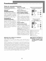
FuncionamientOoooooooooooooooooooooooooooooooooooooooooo
Panel de Control Electr6nico
Control de Alimentaci6n
Este bot6n pone ell marcha y apaga el acondicionador de aire.
Indicador deTemperatura de Ajuste/Temporizador
El indicador muestra la temperatura de ajuste cuando el acondicionador de aire est,_
ell funcionamiento y las horas cuando se ha activado el temporizador. EL
INDICADOR DE LA TEMPERA TURA SOLAMENTE MUESTRA LA TEMPERATURA DE
AJUSTE, NO LA TEMPERATURA AMBIENTE REAL.
Control de la Temperatura/Temporizador
Estos botones se usan para aumentar o reducir la temperatura de ajuste en
incrementos de 1°, entre 66°F hasta 88°F. Si se oprimen simult,_neamente ambos
botones, el indicador digital cambiar,_ entre grados Celsius y Fahrenheit. Cuando se
activa el temporizador, estos botones son usados para cambiar el ajuste de la hora en
incrementos de 1, entre 00 hasta 24.
Selector de Modo
Una luz verde indicar,_ el modo que est,_siendo utilizado.
Modo 'Cool" (Frio) -
El acondicionador de aire circula y enfria el aire.
Modo 'Heat" (Calor) [Solamente los Modelos con Calor] -
El acondicionador de aire circula y calienta el aire.
Caracterfstica de Seguridad del Calentador - Cuando el calentador est,_ apagado, el
ventilador de baja velocidad se activar,_ y funcionar,_ durante 60 segundos para
asegurar la eliminaci6n de alg0n calor residual, a la vez que el diodo LED 'Low Fan'
(ventilador de baja velocidad) destella hasta que se detenga el ventilador de baja
velocidad.
Modo 'Fan" (Ventilador) -
El acondicionador de aire solamente har,_circular el aire.
Modo 'Energy Saver"
(Ahorro de Energia) -
(El modo de ahorro de energia est_ diseffado para funcionar solamente con el modo
'Cool'). El ventilador cambiar,_ de la velocidad de ajuste a velocidad baja cuando el
compresor sea apagado por el termostato. Cuando el compresor se activa
nuevamente, el ventilador volver,_ al ajuste original. La velocidad del ventilador
cambia autom,_ticamente seg0n cambie la temperatura en la habitaci6n.
Control de la Velocidad del Ventilador - Alta, Mediana,
Baja y Autom@tica
El ajuste de la velocidad del ventilador se cambia cada vez que se oprime el
bot6n de control de velocidad del ventilador. Una luz verde indicar,_ el ajuste
que se ha seleccionado.
Cuando se selecciona 'Auto' (Autom,_tico) y el acondicionador de aire est,_ en el
modo 'Cool' o 'Heat', la velocidad del ventilador cambiar,_ autom,_ticamente a
medida que cambie la temperatura en la habitaci6n. En el modo 'Cool', cuando
la habitaci6n Ilega a 7° o m_s,sobre la temperatura de ajuste, se usa 'High Fan'
(Alta Velocidad), cuando la temperatura en la habitaci6n es de 4° o menos, sobre
la temperatura de ajuste, se usa 'Low Fan' (Velocidad Baja). En el modo 'Heat'
cuando la habitaci6n alcanza 7° o m,_s, bajo la temperatura de ajuste, se usa
'High Fan', cuando la habitaci6n alcance 4° o menos, bajo la temperatura de
ajuste, se usa 'Low Fan'. En todos los otros casos el ventilador usa 'Medium Fan'
(velocidad mediana).
Control Electronico
(Enfriamiento Solamente)
® Cool
e Energy Save
• Fen
,g Delay
Control Electronico (Calor/Frio)
Built in Three Minute Cooling Delay
Q Indicador de Temperatura/Temporizador
Ajuste de la Temperatura y del
Temporizador
Q EncendidotApagado del Temporizador
Q Control de la Velocidad de[ Ventilador
O Selector de Modo
Q Control de Alimentaci6n
14

Control del Temporizador (El temporizador puede ser
ajustado ya sea para encender o apagar el acondicionador de aire.)
Para PONER EN MARCHA autom_ticamente el
acondicionador de aire usando el modo "Timer'."
1. Oprima el bot6n 'Timer' cuando la alimentaci6n el6ctrica
est6 desconectada. El indicador mostrar,_ 00. Ajuste el
indicador para que muestre el mimero de horas que desea que
transcurran antes de la PUESTA EN MARCHA, usando las
flechas de ajuste 'Temperature/Timer'
(Temperatu ra/Temporizador).
2. El indicador mostrar,_ la cantidad de horas que faltan para
la PUESTA EN MARCHA.
3. Para salir del modo 'Timer', oprima el bot6n 'Timer'.
4. Una luz verde situada junto al bot6n 'Timer' se iluminar,_
para indicar que el 'Timer' est,_ activado.
Para APAGAR autom_ticamente el acondicionador de aire
usando el modo "Timer'."
1. Oprima el bot6n 'Timer' cuando la alimentaci6n el6ctrica
est6 conectada. El indicador mostrar,_ 00. Ajuste el indicador
para que muestre el mimero de horas que desea que transcurran
antes de que se APAGUE usando las flechas de ajuste
'Temperature/Timer' (Temperatura/Temporizador). (Despu6s de
10 segundos, el indicador volver,_ autom,_ticamente a la
temperatura de ajuste.)
2. Para ver la cantidad de horas que faltan para que se
APAGUE el acondicionador de aire, oprima una vez el bot6n
'Timer'.
3. Para salir del modo 'Timer', oprima el bot6n 'Timer' dos
veces.
4. Una luz verde situada junto al bot6n 'Timer' se iluminar,_
para indicar que el 'Timer' est,_ activado.
Control Electronico
(Enfriamiento Solamente)
T_mer
Hiqh Auto
I I
Med Low
o Cool
• Energy Save
e Fan
gDelay
Control Electronico (Calor/Frio)
Built in Three Minute Cooling Delay
Q Indicador de Temperatura/Temporizador
Ajuste de la Temperatura y del
Temporizador
Q Encendido/Apagado del Temporizador
Control de la Velocidad del Ventilador
O Selector de Modo
Q Control de Alimentaci6n
Calefacci6n (Modelos con Calefacci6n
Solamente)
1. Cierre la puerta de ventilaci6n.
2. Gire el termostato a la posici6n 'Warmer' (M,_s Caliente).
3. Gire el control maestro a 'High Heat' (Calor Alto).
4. Si la habitaci6n est,_ demasiado caliente para ser confortable,
gire el termostato a la derecha hasta que se apaguen los
elementos de calefacci6n (el ventilador de circulaci6n del
aire permanecer,_ en funcionamiento). La temperatura se
mantendr,_ autom,_ticamente. Se pueden necesitar ajustes
adicionales del termostato para Iograr el nivel de confort
deseado.
5. Cuando se Iogra el nivel de confort deseado, el control
maestro puede ser girado a 'Low Heat' (Calor Bajo).
6. Para apagar el acondicionador de aireo en caso de una
interrupci6n de energia el6ctrica, gire el control maestro a la
posici6n 'OFF' (Apagado).
15

MantenimientOoooooooooooooooooooooooooooooooooooooooooooo
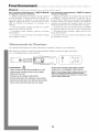
Contyo_ Remote de Acond_donador de Aide
Las funciones trabajan igual que los controles manuales de su acondicionador de aire.
Pilas:
Retire al tapa en la parte trasera del control remoto e inserte las baterias con los polos (+) y (-) en la
direcci6n correcta.
ATENCION
• Use solamente pilas AAA o IEC R03 de 1,5V
• Retire las pilas si el control remoto no va a ser usado
durante un mes o mas.
• No intente recargar las pilas suministradas.
• Todas las pilas deben ser reemplazadas a un mismo
tiempo.
• No incinere las pilas pues pueden explotar.
• No mezcle pilas nuevas con pilas viejas.
• No mezcle pilas alcalinas, standard (carbon-zinc), con
pilas recargables (nickel-cadium).
• Mantenga fuera del alcance de los niffos pequeffos las
pilas y otros articulos que puedan ser tragados.
Pongase inmediatamente en contacto con un medico
si un ni_o pequeffo se traga un objeto.
C) Filtro
®
©
La puerta de ventilaci6n
Rejillas de Ventilaci6n
Circulaci6n del Aire sin Enfriamiento o Calefacci6n
1. Cierre la puerta de ventilaci6n.
2. Gire el control maestro a 'HI FAN' (Alta Velocidad).
Extracci6n del Aire sin Enfriamiento o Calefacci6n
1. Abra la puerta de ventilaci6n.
2. Gire el control maestro a 'HI FAN' (Alta Velocidad).
Direcci6n del Flujo del Aire
El acondicionador de aire ha sido diseffado con rejillas de ventilaci6n ajustables
paraorientarelflujodeaimdescargado. Lasrejillasdeventilaci6nseajustan
manualmente movi6ndolas en la direcci6n deseada del flujo del aim.
Limpieza del Filtro del Aire
Limpie el filtro cada dos semanas
1. Gire el control maestro a 'OFF' (Apagado).
2. Retire el filtro del aim abriendo el panel de entrada del aim situado en el panel
decorativo delantero y sac_ndolo fuera del acondicionador de aim.
3. L_velo en agua con jab6n, enjuague y sacOdalo para secarlo.
4. Vuelva a colocar el filtro con la parte delantera del filtro dirigida hacia usted.
5. Para secar bien el filtro, haga funcionar el acondicionador de aim durante unos
pocos minutos. Recuerde: solamente un filtro limpio puede proporcionar
eficiencia y funcionar de manera correcta en todos los ajustes.
Nota: Si no se mantiene el filtro del aire limpio puede causar
circulaci6n deficiente del aire. NO haga funcionar el acondicionador
de aire sin el filtro. Esto puede impedir que el acondicionador de aire
funcione.
El uso y cuidado adecuado de su acondicionador de aire le asegurar_
una vida dtil prolongada. Se recomienda que inspeccione anualmente
y limpie las espirales y los pasajes del agua del condensado. El costo
de la inspecciSn anual es responsabilidad del propietario.
Atenci6n: Si se apaga el acondicionador de aire espere por Io
menos tres minutos antes de volver a encenderlo.
16

Servicio Para ahorrar tiempo y dinero, verifique Io siguiente antes de Ilamar a un centro de servicio autorizado.
Enfriamiento Insuficiente Calefaccion Insuficiente - Modelos con Calefaccion Solamente
• Coloque el control maestro en la posici6n 'OFF' (APAGADO).
• Cierre todas las ventanas y puertas de la habitaci6n.
• Retire todas las obstrucciones de las rejillas de ventilaci6n
interiores y exteriores.
• Cierre la puerta de ventilaci6n (disponible en algunos
modelos).
• Inspeccione el filtro y limpielo si est,_sucio.
• Gire el termostato y el control maestro al ajuste m,_sfrio.
Bajo ciertas condiciones las espirales de enfriamiento situadas
directamente detr,_s del filtro pueden cubrirse de hielo y bloquear
el flujo del aire. Este es un problema com0n en los
acondicionadores de aire que es causado cuando la temperatura
exterior desciende a menos de 70°F (21°C) y la humedad
permanece alta. Si esto sucede, simplemente apague el
acondicionador de aire y deje que se derrita el hielo, luego
reanude el funcionamiento normal.
• Coloque el control maestro en la posici6n 'OFF' (APAGADO).
• Cierre todas las ventanas y puertas de la habitaci6n.
• Retire todas las obstrucciones de las rejillas de ventilaci6n interiores y
exteriores.
• Cierre la puerta de ventilaci6n.
• Gire el termostato a 'Warmer' (M,_sCaliente) y el Control Maestro a 'HI
HEAT' (Calor Alto).
El Acondicionador de Aire no Funciona
• Gire el control maestro a 'OFF' (APAGADO).
• Vuelva a enchufar el cord6n el6ctrico en un tomacorriente para
asegurarse que est,_ haciendo buen contacto el6ctrico. (Si el contacto
no es firme sedebe reemplazar el tomacorriente).
• Gire el control maestro a 'HI FAN' (Alta Velocidad). Si el ventilador de
circulaci6n del aire no funciona, verifique el disyuntor del hogar (o los
fusibles).
Para los modelos instalados en Norteamerica - Si necesita servicio o repuestos Primero, realice las verificaciones recomendadas anteriormente.
Si considera de que todavia es necesario servicio o repuestos, consulte la secci6n "Como Obtener Servicio o Repuestos bajo la Garantia" incluida
en la garantia de su acondicionador de aire individual.
Para modelos vendidos fuera de Norteamerica - Para los acondicionadores de aire comprados para uso fuera de Norteam6rica, el fabricante no
ofrece ninguna garantia ya sea expresa o implicita. Consulte a su distribuidor local para cualquier garantia que ofrezca el importador en su pals.
Localizaci6n y Soluci6n de Averias
Problema Soluciones
El acondicionador de aire no funciona
Causa Posible
• El enchufe mural esLi desronertado.
• Se ha fundido un fusible o se ha disparado el disyuntor.
El aire proveniente del acondicionador de
aire no es suficientemente frio
El acondicionador deaire enfria,pero la
habitacionesta demasiado tibia - se forma
hielo en las espirales de enfriarniento
detras del panel decorativo delantero
El acondicionador deaire enfria,pero la
habitacionesta demasiado tibia - NOse
forma hielo en las espirales de
enfriamiento detras del panel decorativo
delantero
Se produce ruido cuando el
acondicionador de aire esta enfriando
Goteo de agua dentro del acondicionador
de aire cuando esta enfriando
Goteo de agua fuera del acondicionador de
aire cuando esta enfriando
• El interruptor principal est_ en la posici6n 'OFF'
(APAGADO).
• El acondicionador de aire fue accidentalmente apagado al
nrover el ternrostato a una temperatura nr_s alta y luego se
coloc6 innrediatanrente en una posici6n nr_s frfa.
• El acondicionador de aire se apag6 y luego se encendi6
demasiado r@idamente.
• El ajuste del ternrostato es nruy bajo para enfriamiento.
• El selector est_ en la posici6n 'FAN'(Ventilador).
• El ternrostato est_ en un ajuste demasiado caliente.
• La temperatura de la habitaci6n es inferior a 70°F.
• La temperatura exterior es inferior a 70°F.
• El filtro de aire est,1 sucio- restricci6n del aire.
• El ternrostato est_ en un ajuste demasiado fifo para
enfriamiento nocturno.
• Filtro de aire sucio - restricci6n del aire.
• El ternrostato est_ en un ajuste demasiado caliente.
• El selector de velocidad del ventilador est_ en una
posici6n 'LOW' (Baja).
• Ruido del nrovimiento del aire.
• Ruido del ventilador al golpear el sistenra de extracci6n de
agua y hunredad.
• Vibraci6n de la ventana- instalaci6n deficiente.
• Instalaci6n incorrecta.
• El acondicionador de aire esta extrayendo gran cantidad
de hunredad de habitaci6n.
¢
¢
¢
¢
¢
¢
,/
,/
,/
,/
,/
,/
Inserte bien el enchufe en el tonracorriente mural.
Reemplace el fusible con un tipo de fusible con retardo o reponga
el disyuntor.
Canrbie el interruptor principal a la posici6n 'ON' (ENCENDIDO).
Espere aproximadanrente 3 nrinutos. Escuche si el conrpresor
empieza a funcionar.
Si el acondicionador de aire est_ apagado espere 3 minutos antes
de volver a encenderlo.
Canrbie el termostato a un ajuste m_s alto para enfrianriento.
Coloque el selector en un ajuste 'COOL' (Fifo).
Coloque el termostato en una tenrperatura m_s fria.
No se producir_ enfrianriento hasta que la temperatura de la
habitaci6n no sea superior a 70°F.
Para descongelar la espiral, coloque el selector en la posici6n
'FAN' (Ventilador). Luego coloque el termostato en una posici6n
nr_s caliente.
Linrpie el filtro, vea la secci6n "Limpieza del Filtro del Aire'. Para
descongelar, coloque el selector en la posici6n 'FAN' (Ventilador).
Para descongelar la espiral, coloque el selector en la posici6n
'FAN' (Ventilador). Luego coloque el termostato en una posici6n
nornral.
_/ Limpie el filtro del aire. Consulte la secci6n "Limpieza del Filtro
del Aire'.
_/ Coloque el termostato en un ajuste m_s fifo.
7 Coloque el selector de velocidad del ventilador en 'HI' (ALTO) para
enfriamiento m_iximo.
7 El sonido del aire movi6ndose es normal. Si es demasiado fuerte,
gire el selector a un ajuste del ventilador m_is bajo.
_/ Estoes normal cuando la humedad es alta. Cierre las puertas,
ventanas y rejillas de ventilaci6n.
_/ Consulte las instrucciones de instalaci6n - consulte con el
instalador.
Incline ligeramente el acondicionador de aire hacia el exterior para
desaguar el agua. Consulte las instrucciones de instalaci6n -
verifique con el instalador.
_/ Estoes normal durante dfas excesivamente h0medos.
17

Garantiaoooooooooooooooooooooooooooooooooooooooooooooooooooo
Para modelos instalados en
Norteam6rica - En caso de necesidad
de servicio o piezas
Haga primero las verificaciones recomendadas. En caso
de necesitarse servicio o piezas, consulte en la garantia de
su acondicionador de aire en la secci6n "C6mo obtener
servicio o piezas de garantia".
Para modelos instalados
fuera de Norteam_rica
Para aires acondicionados comprados para uso fuera de
Norteam_rica el fabricante no otorgar_ ninguna garantia
implicita o explicita. Consulte a su distribuidor autorizado
sobre las condiciones de la garantia extendida por el
importador de los equipos de su pais.
Garantia del acondicionador de aire
(Dentro de los 48 estados contiguos de los Estados
Unidos, estado de Hawai, Distrito de Columbia, Puerto
Rico y Canada)
Garantia para todas las piezas (cinco a_os)
y mano de obra
A partir de la fecha de compra y durante un periodo de cinco
afios, Fedders North America, mediante sus estaciones de
servicio autorizadas, reparar_ o reemplazar_ sin costo alguno
para el propietario o usuario, cualquier pieza que presente
daffos de material o mano de obra derivados del uso normal
del producto. Es responsabilidad del propietario facilitar el
acceso al acondicionador de aire para realizar los servicios de
reparaci6n.
Nota: En caso de que se requiera reemplazar una pieza
mientras la garantia esta vigente, se utilizaran los
repuestos de Fedders North America los cuales
continuaran en vignecia solamente durante el resto del
periodo de garantia de la unidad.
Excepciones
La garantia antes indicada no cubre las fallas de
funcionamiento causadas por daffos que sufra la unidad
mientras 6sta est6 en posesi6n del usuario (excluyendo los
daffos causados por defecto o funcionamiento defectuoso), o
por la instalaci6n incorrecta, o la utilizaci6n indebida de la
unidad, incluyendo pero sin limitarse a ello, la negligencia en
proporcionar el mantenimiento necesario y adecuado o en
seguir las "instrucciones de Instalaci6n y Uso" indicadas por
escrito. En caso de utilizarse la unidad para fines comerciales,
de negocios, de arriendo u otro uso o aplicaci6n que no sea el
uso del consumidor, no otorgamos garantia explicita ni
implicita, incluyendo, pero sin limitarse a, toda garantia
implicita de negociabilidad o idoneidad para un uso o
finalidad particular.
LAS SOL UCIONES EXPUESTAS EN LA GARANTIA ANTERIOR
SON EXCLUSIVAS. SE RECHAZA CUALQUIER OTRA
GARANTIA YA SEA EXPRESA 0 IMPLICITA, INCLUYENDO,
PERO SIN LIMITARSE A ELLO, TODAS LAS GARANTIAS DE
COMERCIABILIDAD 0 IDONEIDAD PARA UN FIN EN
PARTICULAR DURANTE CINCO ANOS A PARTIR DE LA
FECHA DE COMPRA. BAJO NINGUNA CIRCUNSTANCIA
FEDDERS NORTH AMERICA SE HARA RESPONSABLE POR
NINGUN DAI_IO DIRECTO, INDIRECTO 0
CONSECUENCIAL, SIN IMPORTAR LA CAUSA DE LA
ACCION, AUN CUANDO FEDDERS NORTH AMERICA HAYA
SIDO ADVERTIDO CON ANTERIORIDAD DE LA
POSIBILIDAD DE DICHOS DANOS. NO SE OFRECE
NINGUNA GARANTIA EXPRESA 0 IMPLICITA A
COMPRADORES DESPUES DE LA REVENTA.
Algunos estados no permiten limitar el tiempo de duraci6n de
una garantia implicita ni permiten excluir ni limitar los daffos
incidentales o emergentes, de modo que las limitaciones o
exclusiones antes indicadas podrian no aplicarse en su caso.
Esta garantia le otorga derechos legales especfficos. Usted
podria tener tambi6n otros derechos que pueden variar de
estado a estado.
No se ofrecen garantias para las unidades vendidas fuera de las
_reas antes indicadas. Su distribuidor o vendedor final podria
proporcionar una garantia para las unidades vendidas fuera de
estas _reas.
C6rno obtener servicio
o piezas de garantia
El servicio para su acondicionador de aire ser_ provisto por
CareCo, una divisi6n del fabricante con estaciones de servicio
independientes CareCo autorizadas en todo el pais.
Nora: Antes de solicitar servicio, lea cuidadosamente el
folleto de "lnstrucciones de Instalacion y Uso'."Luego, si
necesita servicio:
1. Llame a un taller de servicio autorizado CareCo y
suministreles el n0mero de modelo, n0mero de serie, la fecha
de compra y la naturaleza del problema. El servicio se
prestar_ durante horas normales de trabajo. Comuniquese con
su distribuidor para obtener recomendaciones sobre una
estaci6nde servicio autorizada.
2. Si su distribuidor no puede proporcionarle el nombre de un
taller de servicio o si necesita otro tipo de asistencia, Ilame
al siguiente n0mero gratis para obtener el nombre de un
taller de servicio autorizado o distribuidor de piezas
autorizado:
1-866-MAYTAG 1
o escriba al."
Departamente de Servicio de CareCo
415 W. Wabash Ave., RO. Box 200
Effingham, IL 62401 EE. UU.
Prueba de la fecha de compra
El establecimiento de la fecha de compra original para efectos
de la garantia es responsabilidad del consumidor.
Recomendamos mantener la factura de compra, el cheque
cancelado o algOn otro registro de pago apropiado para dicho
efecto.
18

Directives de s6curit6
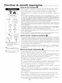
CALIBRE RECOMMANDE DES
CONDUCTEURS
(selon le code du b_timent) :
CAPACIT[_ CALIBRE DES
DU FUSIBLE CONDUCTEURS
15A N° 14ou plusgros
20A N° 12ou plusgros
30A N° 10ou plusgros
©©
125V 250V
15A 20A
©©
250V 250V
15A 30A
(_ Fiche de branchement _ trois
broches (liaison _ la terre).
Ne pas modifier la fiche de
branchement.
(_) Prises de courant murales
trois alvdoles(liaison _ la terre).
C) Prise de courant murale simple
avec liaison _ la terre.
; ,, * *.m vor.an.es ooooooooooooooooooooo
A
Risque de choc _lectrique _J_
• Brancher I'appareil uniquement sur une prise de courant dectrique reli_e _ la terre.
• Ne pas utiliser avec cet appareil un cable de rallonge ou un adaptateur de fiche.
• Ne pas faire fonctionner cet appareil Iorsque le panneau de faqade est enlev6.
• Le non-respect de ces pr6cautions peut entratner choc 61ectrique, incenclie ou
blessures.
• Si les param6tres cl'alimentation 61ectrique sur la plaque signal6tique sont 115 volts et
7,5 A ou plus, il faut que I'appareil soit prot6g(_par son propre fusible ou disjoncteur,
et aucun autre appareil ne clevrait 6tre branch6 sur le m6me circuit cl'alimentation. Si
la plaque signal6tique clu climatiseur inclique qu'il cloit 6tre aliments sous 230 volts,
il faut que I'appareil soit prot6g6 par son propre fusible ou disjoncteur, et aucun autre
appareil ne clevrait 6tre branch6 sur le m6me circuit cl'alimentation.
• II est recommand6 qu'un 61ectricien qualifi6 installe I'appareil conform6ment aux
prescriptions clu code national des installations 61ectriques et des codes et r6glements
Iocaux applicables.
• Ne pas faire fonctionner ce climatiseur si le circuit d'alimentation n'est pas prot6g6 par
un fusible ou disjoncteur chrometr6 de capacit6 convenable. Pour les caract6ristiques
d'alimentation 61ectrique, voir la plaque signal6tique de I'appareil.
• Utiliser uniquement des conclucteurs en cuivre et clispositifs de protection de calibre
et de capacit6 ad6quate.
• Ne pas modifier le cordon d'alimentation ou la fiche de branchement. N'enlever
aucune 6tiquette cl'avertissement fix6e sur le cordon d'alimentation.
/'L
Liaison _ la terre - Exigences importantes
• Pour la protection des utilisateurs contre les risques de choc 61ectrique, le climatiseur
comporte un cordon d'alimentation muni d'une fiche de branchement _ trois broches
(liaison _ la terre) qu'on doit brancher sur une prise de courant murale _ trois alv6oles
convenablement reli6e _ la terre. Pour un modde dont la demande de courant est de
7,5 A ou moins, utiliser une prise de courant murale reli6e _ la terre de m6me
configuration que la fiche de branchement.
• Pour un mod6le clont la clemande de courant est sup6rieure _ 7,5 A, utiliser une prise
de courant simple avec liaison _ la terre, de m6me configuration que la fiche de
branchement.
Mesures de s_curit_ additionnelles
*Ne pas couper, modifier ou enlever aucun des composants de polystyrene expans_
(materiel isolant blanc) plac6s _ I'int6rieur du climatiseur.
• Ne jamais remiser ou utiliser d'essence ou autre produit inflammable liquide ou
gazeux au voisinage des appareils ou de tout autre appareil m6nager. Les vapeurs
6mises pourraient entratner un risque d'incendie ou d'explosion.
• N'introduire aucun objet dans la zone de d6charge de I'air; ceci pourrait provoquer
une d6t6rioration non r6parable de I'appareil.
• Ne verser aucun liquide sur le climatiseur; ceci pourrait entratner une anomalie de
fonctionnement. Pour le nettoyage de I'appareil, utiliser un chiffon humide.
• Lorsdu nettoyage du climatiseur, 6viter d'employer un solvant 6nergique.
• Pour 6viter une obstruction et un 6chauffement excessif, nettoyer le filtre du
climatiseur _ intervalles de deux semaines.
• Veiller _ ne pas obstruer les entr6es d'air clu climatiseur; ceci provoquerait un
6chauffement excessif et le d6clenchement des dispositifs de s6curit6 qui provoquent
I'arr6t de I'appareil.
• Ne pas bloquer la circulation de I'air vers les claires-voies ext6rieures de la caisse.
• Ne pas bloquer la circulation de I'air au voisinage de I'appareil, _ I'int6rieur (stores,
rideaux, meubles), ou _ I'ext6rieur (arbustes, enceintes ou autre b._timent).
• Ne pas faire fonctionner le climatiseur Iorsque la housse de protection est en place.
Ceci pourrait faire subir des dommages m6caniques au climatiseur.
19

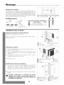
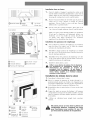
Montage°°°°°°°°°°°°°°°°°°°°°°°°°°°°°°°°°°°°°°°°°°°°°°°°°°°°
Dimensions de la fen_tre
Ce climatiseur a 6t6 configur6 _ I'usine pour I'installation dans une
fen6tre _ guillotine standard (double) offrant une largeur libre de 68,3 cm
(26,875 po) _ 105,7 cm (41,625 po) et une hauteur libre d'au moins 39,7
cm (15,625 po)(depuis le bas de I'ouvrant mobile jusqu'au seuil de
fen6tre). On peut installer I'appareil dans une fen6tre offrant une largeur
libre de 3/8 po, apr_s d6pose des joints lat6raux.
60 cm (23-5/8 po) ,_ 39,7 cm (15,625 po)
(_) 105,7 cm (41-5/8 po) (_ min.
Outillage n6cessaire
Tournevis
Niveau
CI6 _ cliquet
Ruban _ mesurer
Contenu de I'ensemble d'installation
No. Nom de la piece Q't6
g Visa bois - 25mm (lpo) 1
Visa bois 15.875mm (5/8 po) 5
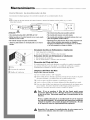
Installation dans un frente
Enlevement du panneau de facade d6coratif
1. Retirer les vis de chaque c6t6 de la caisse.
2. Tirer avec pr6caution vers I'avant tout tenant bien les deux c6t6s du
panneau de facade.
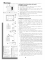
IZenlevement du chassis
1. En bas, _ I'arri_re de la caisse, sur les c6t6s, enlever les deux (2) vis
plac6es avant I'exp6dition.
2. En bas, _ I'avant, sur les c6t6s de la caisse, 6ter les deux (2) vis
antivol. CONSERVER CES VIS; elles seront r6utilis6es durant
I'installation.
3. Faire glisser le ch&ssis pour le faire sortir de la caisse - saisir la
poign6e du plateau et tirer vers I'avant.
"3/8" sheet metal screw
Installation des panneaux de remplissage
1. Faire coulisser le cadre du panneau de remplissage sur la caisse du
climatiseur en utilisant les tringle sup6rieure et inf6rieure de
I'appareil. Faire coulisser le cadre aussi pros que possible du
climatiseur de mani_re que le rideau se verrouille en place.
2. Tirer sur le cadre avec pr6caution jusqu'_ ce qu'il se trouve _ la bonne
Iongueur.
Travailler prudemment au voisinage des ar_tes
expos_es de la caisse et des ar_tes acCrUes de
I'_changeur de chaleur, pour _viter de se blesser ou
de d_chirer les v_tements.
20
C) Caisse (_ Panneau de facade
C) Vis de phillips d6coratif
C)Vis utilis6es pour I'exp6dition (_ Ch&ssis
C)Caisse (_ Poign6e
(_Vis antivol
(_Tringle supdrieure 1_ Bord de verrouillage
(_ Cadre du Panneau de (_ Tringle infdrieure
remplissage (D Caisse
La page est en cours de chargement...
La page est en cours de chargement...
La page est en cours de chargement...
La page est en cours de chargement...
La page est en cours de chargement...
La page est en cours de chargement...
La page est en cours de chargement...
La page est en cours de chargement...
-
 1
1
-
 2
2
-
 3
3
-
 4
4
-
 5
5
-
 6
6
-
 7
7
-
 8
8
-
 9
9
-
 10
10
-
 11
11
-
 12
12
-
 13
13
-
 14
14
-
 15
15
-
 16
16
-
 17
17
-
 18
18
-
 19
19
-
 20
20
-
 21
21
-
 22
22
-
 23
23
-
 24
24
-
 25
25
-
 26
26
-
 27
27
-
 28
28


Maytag 23-11-2229N-004 Manuel utilisateur
- Catégorie
- Climatiseurs split-system
- Taper
- Manuel utilisateur
dans d''autres langues
- English: Maytag 23-11-2229N-004 User manual
- español: Maytag 23-11-2229N-004 Manual de usuario
Documents connexes
Autres documents
-
 Air Temp B7Y15F2A Le manuel du propriétaire
-
Fedders 23-23-0355N-002 s Installation & Operation Manual
-
Fedders aed24e7f Manuel utilisateur
-
-
-
-
-
-
-
