Fedders 23-11-2120N-003 Installation & Operation Manual
- Catégorie
- Climatiseurs split-system
- Taper
- Installation & Operation Manual
Ce manuel convient également à

Room Air Conditioner
Installation & Operations Manual
Room air conditioners for
double hung windows &
through-the-wall Installation
Acondicionadores de aire para
ventanas de guillotina y
empotrados en la pared
ENGLISH
Important Safet_ Instructions .................................... 2
Installation ..............................................................
Operation ............................................................... 8
Maintenance ........................................................... 9
Warranty ............................................................. 10
ESPAI_IOL
Instrucciones importantes de seguridad .................. 11
Instalaci6n ............................................................. 12
Funcionamiento .................................................... 17
Mantenimiento .................................................... 18
Garantia ............................................................... 19
Climatiseurs- Installation dans
un mur ou une fen_tre
guillotine
FRANCAIS
Directives de s_curit_ importantes ........................ 20
Installation ............................................................ 21
Utilisation ............................................................ 25
D6pannage ......................................................... 26
Garantie ................................................................ 27
For Future Reference
Write down the model and serial numbers
The model and serial numbers can be found on the side of the
cabinet near the control panel. Use these numbers in any
correspondence or service calls concerning your air
conditioner.
Para referencia futura
Escriba el numero de modelo y de serie
El ndmnero de modelo y de serie se encuentran en el costado
del gabinete cerca del panel de control. Use estos n(imeros en
toda la correspondencia o Ilamadas de servicio relacionadas
con su acondicionador de aire.
Pour consultation ult_rieure
Inscrivez les numeros de modele et de serie
Noter ci-contre les num6ros de module et de s6rie (on les
trouve sur le c6t6 de la grille ddcorative avant, pros du tableau
de commande). Communiquer ces numdros Iors de toute
correspondance ou appel au service apr_s-vente ayant trait au
climatiseur.
Model No., No. de Modelo, N° de module
Serial No., No. de Serie, N° de s6rie
Date of Purchase, Fecha de Compra, Date d'achat
For additional questionsplease call
1-217-347-6459
Para mayor informacion por favor Ilame al
1-217-347-6459
o envie correo electronico a:
Pour d'autres questions: 1.217.347.6459

/'IMPORTANT SAFETY INSTRUCTIONS-']
ELECTRICAL REQUIREMENTS & SAFETY PRECAUTIONS J
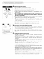
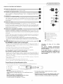
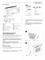
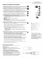
RECOMMENDED CIRCUIT
WIRE SIZES
(As installed per building code) :
PROTECTOR SIZE WIRE GAUGE
30 AMP #10 MINIMUM
©
250V
30A
"-"0
©
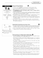
(_ Three-prong grounding
plug.
Do not alter plug end.
I_ Single outlet grounding wall
receptacle
A
Electrical Shock Hazard
• Plug unit only into grounded electrical outlet.
• Do not use an extension cord or plug adapter with this unit.
• Do not operate unit with decorative front or filter removed.
• Failure to follow these precautions could result in electrical shock, fire or
personal injury.
• The air conditioner has a serial plate rating of 230 volts. It must have its own
fuse or circuit breaker, and no other device or unit should be operated on
that fuse or circuit breaker.
• We recommend that a qualified electrician install unit in accordance with the
National Electrical Code and local codes and ordinances.
• Do not operate this air conditioner without proper time delay circuit
protection (circuit breaker or fuse). Refer to serial plate for proper power
supply requirements.
• Use copper conductors of correct wire gauge and protector size only.
• Do not alter cord or plug end. Do not remove warning label on cord.
Important Grounding Requirements
• Air conditioner has a three-prong grounding plug on the power supply cord,
which must be plugged into a properly grounded three-prong wall receptacle
for your protection against possible shock hazard.
• Use a single outlet grounding type wall receptacle to match the cord plug.
(Fig. 2)
A
Additional Safety Precautions
• Do not cut, alter or remove any of the expanded polystyrene (styrofoam)
inside this air conditioner.
Do not store or use gasoline or other flammable vapors and liquids in the
vicinity of this or any other appliance. The fumes can create a fire hazard or
explosion.
Do not introduce objects in the air discharge area. This could cause
permanent damage to your unit.
Do not pour liquids on the air conditioner as this could cause a malfunction.
With the unit unplugged, use a damp cloth for cleaning your unit.
Avoid using strong solvents to clean the air conditioner.
Clean the air conditioner filter every two weeks to avoid overheating caused
by air obstruction. Do not operate without filter.
Do not obstruct the air intake area of your air conditioner, as this could cause
overheating, thus activating the units security switch and shutting off the unit.
Do not block air circulation to outside louvers of cabinet.
Do not block air flow inside with blinds, curtains, or furniture, or outside with
shrubs, enclosures, or other buildings.
Do not run the air conditioner with an outside protective cover in place. This
could result in fire or mechanical damage within the air conditioner.

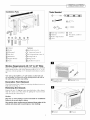
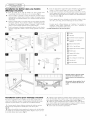
Installation Parts
® © © ®
© @
Tools Needed
t)
® Blade-type screwdriver ® Knife
O Hammer (_ Hex driver, ratchet or
(_ Rule or tape measure wrench
(_ Level
C) Cabinet
(_ Sliders
C) Filler panel
Side Seal
(_ Sill bracket
® Support bracket
(_ Foam
Fasteners:
®Hex head screw (6)
®1" long wood screw (6)
©5/8" long machine screw (2)
®Carriage bolt (2)
(_Flange nut (4)
(_)Upholsterer's tack (6)
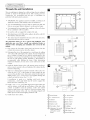
Window Requirements 28 1/2" to 40" Wide
This air conditioner is factory prepared for installation ill standard
double-hung windows with actual opening width of 28 1/2" to 40"
and clear, vertical opening of 21" minimum from bottom of sash to
sill.
Note: Unit can be installed in a 27" wide window, if cabinet side seals
are not installed. Use foam seal to fill any openings between the sidesof
the cabinet and the window stop molding.
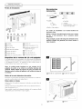
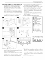
Decorative Front Removal
Detach front panel from cabinet by removing attachment screws on
both sides of unit (Fig. 3).
Removing the Chassis
Remove the two (2) shipping screws from both sides of the cabinet.
Slide the chassis out of the cabinet by pulling the chassis forward
while bracing the cabinet (Fig. 4).
Caution:
Use two or more people to move and install air conditioner.
Failure to do so can result in injury.
Use caution when working around exposed sharp edges of the
cabinet and sharp coils to avoid injury or torn clothing.
M
[_) Decorative front (_ Shipping Screw
retaining screw
IBII
C)Cabinet (_ Chassis

"'INSTALLATION -']
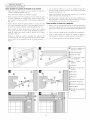
WINDOW IN STALLATON
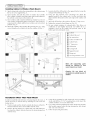
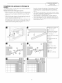
Installing Cabinet in Window (Flush Mount)
1. Attach cabinet side seals to the existing holes ill the cabinet using
2.
the six (6) screws supplied (Fig. 5).
Open window and mark the center of window sill. Carefully
place cabinet in window and align center mark on the bottom tie
bar with the center mark on the window sill.
3. Close window until it touches behind top retainer bar. Do not
close window so tightly that sliders cannot move. (Do not release
your grip on the cabinet until the lower window sash is in its final
position.) (Fig. 6)
4. Attach the cabinet to the window sill by driving two (2) 1" long
screws through each cabinet track into the window sill (Fig. 7).
5. Loosely attach the sill bracket to the support bracket, using the
carriage bolt and flange nut (Fig. 8).
6. Using 5/8" long machine screw and flange nut, attach the
support bracket to the cabinet track. Use the track hole that
aligns with the sill bracket on the outer edge of the window sill
(Fig. 9).
7. Attach the sill bracket to the window sill using 1" long screws.
8. Tighten the carriage bolt and flange nut. (Fig. 10)
9. Be sure cabinet maintains its outward pitch. This allows air
conditioner to slant slightly downward (1/2 bubble off on a
carpenter's level) on the outside and prevents water in the
bottom pan from entering the room.
W
©
(_) Cabinet
(_ Cabinet Side seal
C) Top retainer bar
(_ Center of window sill
(_) Cabinet Track
(_ 1" long screw
C) Sill Bracket
C) Carriage bolt
(_ Support bracket
(_ Flange nut
(_ 5/8" long machine screw
Note: All supporting parts
should be secured to firm
wood, masonry or metal.
Caution: Do not block air
circulation to outside louvers of
cabinet.
Installation Other Than Flush Mount
Ill order to install the unit with more of it projecting into the room, it
will be necessary to relocate the top retaining bar, side seals and
bottom tie bar.
1. Check to make sure the cabinet's outside side louvers will not be
blocked when the unit is moved farther into the room.
2. Remove the top retainer bar, cabinet side seals and bottom tie
bar from the cabinet. Relocate them for the desired projection
into the room.
3. Using the top retaining bar and cabinet side seals as templates,
locate and drill five (5) 7/32" mounting holes on the top of the
cabinet and three (3) on each cabinet side.
4. Use sealing material to fill the holes in the cabinet top and sides
that become exposed when the top retaining bar and cabinet
side seals were relocated.
5. Follow all preceding instructions.
4

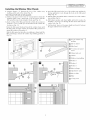
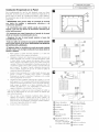
Installing the Window Filler Panels
1. Measure distance "X" between the face of the window stop
molding and the side of the cabinet (Fig. 11).
Note: Measure both sides of unit separately.
2. Subtract one groove (3/1 6") from "X" measurement to obtain the
required width. Using a sharp knife, score the groove until the
filler panel becomes weak enough to break apart (Fig. 12).
3. Insert cut edge of the filler panel into the cabinet side seal groove
(position 1). Leave a small space at the bottom of the cabinet side
seal groove (Fig. 13).
Rotate the filler panel backward toward the window frame until
the filler panel clears the window sill. Push the filler panel down
against the window sill (position 2).
Slide the filler panel out from the air conditioner cabinet until the
filler panel flange contacts the window stop molding (position 3)
(Fig. 14).
4. Attach the filler panel to the face of the window stop molding by
driving upholsterers' tacks through the holes in the filler panel
flange (Fig. 15).
5. Pull the sliders out until the sliders contact the face of the window
stop molding (Fig.1 6).
6. Pull bottom window sash down tightly and lock it in place by
installing a 5/8" long screw through the hole in the slider into the
window sash (Fig. 16).
7. Cut the plastic foam seal to proper length and insert it between
the upper and the lower window sash.
(_ Face of window stop
molding
(_ Side of cabinet
C) Filler Panel
I_ "X" minus one groove
(3/1 6")
(_ Cabinet side seal
(_ Cabinet
_) Window stop molding
I_ Position 1
I_ Position 2
(_ Position 3
(_ Holes in flange
(_ Upholsterers' tacks
I_ Hole in slider
I_ Slider
(_ 1" long screw
........ _Q
Will//
0
!i!!i!!i!!i!i!i!
iiifill!iiiii

_ INSTALLATION -'_
HRU-WALL INSTALLATION
Through-the-wall Installation
This air conditioner is designed as a slide-out type chassis, making it
possible to install it through-the-wall in both existing and new
construction. We recommend that this type of installation be
performed with professional assistance.
• IMPORTANT: This appliance must be installed according to all
applicable electrical and building codes and ordinances.
• It is recommended that you have help to install your unit and
that you use proper lifting technique to avoid personal injury.
• It is important that you inspect the condition of the wall where
the air conditioner will be installed.
• Be sure the wall call support the weight of the unit.
• All cabinet louvers MUST BE on the outdoor side of the wall. DO
NOT BLOCK SIDE LOUVERS.
• The cabinet must be installed level from side-to-side and with a
downward tilt from inside to outside.
The instructions
application may
importer before
manual.
below are for a typical wall installation. Your
vary. Please consult your authorized dealer or
attempting any installation not covered in this
1. First remove the Decorative front panel and chassis from the
cabinet, then remove top bar from the cabinet.
2. Determine the size of the opening for a wood frame by adding
1/8" to the width and height of the cabinet. Measure height from
top of cabinet to bottom of bar. Add this measurement to the
thickness of wood used to build the frame. This will determine
the size of wall opening needed. Minimum 1" thick lumber is
recommended when building the frame. When determining
finish frame thickness, be sure not to cover side louvers on the
cabinet.
3. Install the finished frame in the wall opening square and level,
nail or screw it securely to the wall and place the cabinet into the
framed wall opening.
4. Make sure cabinet projects into the roomside of the wall 1 1/4"
at the top and 1 1/2" at the bottom to ensure proper tilt and
access to the anti-theft screw, then fasten cabinet to the frame by
drilling twelve (12) 1" wood screws (not supplied) through the
cabinet and into the frame. (Fig. 17 & 18)
If installation is made in a building with brick veneer
construction, a steel angle lintel must be used to support the
bricks above the cabinet.(Fig. 19)
5. Install a 3/4" X 1 1/2" wood filler strip between the bottom bar
and the interior, caulk both top and bottom of this strip. After
cabinet is installed caulk all openings, inside and outside
between finish frame and cabinet to prevent moisture from
getting to the interior of the wall. Use of flashing (driprail) will
further prevent water from dripping inside the wall.
6. Install chassis into cabinet.
[ii
.........g g g i ........°
I I
6
1_ Wood frame
D 1" wood screws
(D Cabinet
I_ Bottom Bar
I_ Interior wall
I_ Decorative Front
Q Minimum lx6 wood
support (nailed or
screwed to wood
frame)
1_2" Wood frame
1_1 1/2" space
1_1 1/4" space
(DBrick veneer
I_Lintel angle
(_Caulking
t_Flashing (drip rail)
(_Side louvers
(_Wood filler strip

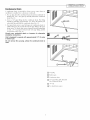
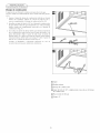
Condensate Drain
A condensate drain is provided to divert excess water when air
conditioner is installed over a doorway or sidewalk.
1. Pry cap plug from the condensate drain (located on underside of
bottom pan). Use a 3/8" pipe tap and fully thread the condensate
drain (Fig. 20).
2. Screw a 3/8" pipe fitting into the condensate drain. The fitting
should be protruding approximately 1/2" above the bottom pan
when fully threaded into the condensate drain (Fig. 21 ).
3. If an open drain source is used to dispose of condensate, plastic or
rubber tubing may be run directly from the pipe fitting to the open
drain source. If closed drain source (internal structural plumbing)
is used, a "P" trap must be between the 3/8" pipe fitting and the
closed drain source (Fig. 22).
Consult your authorized dealer or importer for alternative
installation instructions.
Unit is designed to operate with approximately 1/2" of water
in bottom pan.
Do not remove the cap plug, unless the condensate drain is
used.
C) Cap plug
(_ Bottom pan
Q Condensate drain
(_ 3/8" pipe fitting fully threaded
into condensate drain
(_ "P" trap
C) To dosed drain source
7

F PERATION -"}
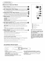
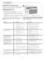
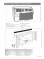
ELECTRONIC CONTROLS
Electronic Control Panel
(_) Power Control
The Power Control turns the unit on and off.
@ Set Temperature/Timer Display
Shows the set temperature when the unit is in operation and hours when the timer is being
set. THE TEMPERATURE DISPLAY ONLY SHOWS THE SET TEMPERATURE, NOT THE
ACTUAL ROOM TEMPERATURE.
Q Temperature/Timer Hour Controls
These buttons are used to raise or lower the set temperature. By depressing both buttons at
once, the display will toggle between Celsius and Fahrenheit. When the timer is being set,
these buttons are used to change the hour setting in increments of I hour from 00 to 24.
@
Mode Control
A green light will indicate which mode is currently being utilized
Cool Mode - The unit will circulate and cool the air
Fan Mode - The unit will only circulate the air
Energy Saver Mode - The fan will switch from the set fan speed to LOW whenever the
compressor turns off in response to the thermostat. When the compressor cycles back on,
the unit will return to the original fan setting.
®
Fan Speed Control- High, Low, and Auto @
The fan speed is adjusted with the Fan Speed Control, each time the button is depressed it
changes the setting. A green light will indicate which setting is currently being used.
Auto Feature -When the AUTO feature is selected while the air conditioner is in the
COOL mode, the fan speeds will change automatically as the temperature in the room
changes.
• High fan: If the room temperature is 4 ° or more above the set temperature.
• Low fan: If the room temperature is less than 4 • above the set temperature.
(_ Timer Control The timer can be set to either turn the unit on or off. _ @
To turn the unit on using the Timer:
Depress the timer key when the power is off, the display will read 00. Adjust to the desired
number of hours before TURN ON using the up/down arrows.
The display will show the time by hours left until TURN ON.
To Turn the timer off, depress the timer key.
A green light next to the Timer Control indicates that the timer is set.
To turn the unit OFF using the Timer:
Depress the timer key when the power is on, the display will read 00. Adjust to the desired
number of hours before TURN OFF using the up/down arrows. The display will
automatically go back to the set temperature after 10 seconds.
To display the amount of time left until TURN OFF, depress the timer button once.
To turn the TIMER OFF, depress the timer button twice.
A green light next to the Timer Control indicates that the timer is set.
!2Oo
® COOL e FAN @
ONIO_
®
Power Control
Temperature/Timer Display
_ emperature/Timer Controls
Mode Control
0 Fan Speed Control
0 Timer On/Off
Built-in three minute timing delay.
This electronic controlled unit will
not automatically resume operation
after a power failure.
ff this electronic unit will not respond
to touch pad or remote control
commands, it is necessary to unplug
the unit from the electrical outlet for
five seconds and then plug the unit
back in.
Air Conditioner Remote Control
The functions work the same as your air conditioner's touch controls.
o
CAUTION:
• Use only AAA or IEC R03 1.5V batteries.
• Remove the batteries if the remote controller is not used for a
month or longer.
• Do not attempt to recharge the supplied batteries
• All batteries should be replaced at the same time.
• Do not dispose of the batteries in a fire as they may explode.
• Do not mix old and new batteries.
• Do not install the batteries with the polarity (+/-) reversed.
• Keep batteries and other things that could be swallowed away
from young children. Contact a doctor immediately if an object
is swallowed.
• Do not mix alkaline, standard (carbon- zinc), or rechargeable
(nickle-cadmium) batteries.
8

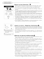
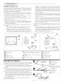
Directing Airflow
Unit is engineered with adjustable louvers to direct discharge airflow.
Louvers are manually adjusted by moving levers ill direction of
desired airflow (Fig. 23).
Cleaning Air Filter EVERYTWOWEEKS:Clean the filter.
1. Turn unit off.
2. Remove the air filter by grasping the top corners and pulling it Lip
and out of the unit (Fig. 23).
3. Wash in hot soapy water, rinse and shake dry.
4. Replace the filter, with the front of the filter toward you.
5. To dry the filter thoroughly, run your unit for a few minutes.
Remember, only a clean filter works properly and delivers top
efficiency at every setting.
air filter clean will result in
Note: Failure to keep
poor air circulation.
DO NOT operate
the unit inoperative.
Filter @ Louvers
Proper use and care of your air conditioner will help ensure longer life of the unit.
without filter. This can render It is recommended to annually inspect and clean the coils and condensate water
passages. Expense of annual inspection is the consumers' responsibility.
Service To save time and expense, check the following before calling an authorized servicer.
Insufficient Cooling
• Shut all windows and doors in room.
• Remove any obstructions from inside and outside louvers.
• Inspect filter and (-lean if dirty.
Under certain conditions the cooling coils directly behind
the filter, may ice up and block the airflow. This is a common
occurrence in air conditioners caused when the outside
temperature drops below 70°F (21°C) while the humidity
remains high. If this happens, simply turn the unit off and
allow the ice to melt, then resume normal operation.
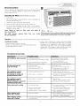
Troubleshooting Guide
Occurrence
Air conditioner will not operate
Air from unit does not
feel cold enough
Air conditioner cooling,
but room is too warm
ice forming on cooling coil
behind decorative front
Air conditioner cooling,
but room too warm --
NO ice forming on cooling coil
behind decorative front
Noise when unit is cooling
Possible Cause
• Wall plug disconnected.
• House fuse blown or circuit breaker tripped.
Unit turned off and then on too quickly. V"
Thermostat set too low for cooling. V"
Unit in Fan mode.
Temperature set too high.
Room temperature below 70°F.
• Outdoor temperature below 70°F.
• Dirty air filter air restricted.
• Dirty air filter air restricted.
• Thermostat set too warm.
• Air movement sound.
• Sound of fan hitting water-
moisture removal system.
• Window vibration poor installation.
Water dripping inside • Improper installation.
when unit is cooling
Water dripping outside • Unit removing large quantity of moisture
when unit is cooling from humid room.
Solutions
/ Push plug firmly into wall outlet.
/ Replace fuse with time delay type
or reset circuit breaker.
Wait 3 minutes before restarting.
Adjust thermostat to lower temperature.
Set Mode to Cool.
Set thermostat to lower temperature.
Cooling may not occur until room
temperature rises above 70°F.
To defrost the coil, set mode to Fan.
Then, set thermostat to warmer temperature.
(:lean filter. See "(:leaning the Air Filter" section.
To defrost, set mode to Fan.
/
/
/
/
/
/
/
/
/
/
/
/
Clean air filter.
Refer to "Cleaning Air Filter" section.
Set thermostat to colder temperature.
The sound of rushing air is normal. If too loud,
Fan Speed to Low setting.
This is normal when humidity is high.
Close doors, windows and registers.
Refer to installation instructions
check with installer.
Tilt air conditioner slightly to the outside to
allow water drainage. Refer to installation
instructions check with installer.
This is normal during excessively humid clays.

f" WARRANTY "_
J
How to Obtain Warranty Service
or Parts
Note: Before calling for service, carefully read this
Installation and Operations manual.
For Models Installed in North America :
First make the recommended checks ill the
Troubleshooting guide on page 9. Then, if you still need
assistance:
1. Call a CareCo authorized servicer and advise them of
model number, serial number, date of purchase and
nature of complaint. Service will be provided during
normal working hours. Contact your dealer for the
name of an authorized servicer, if unknown to you.
2. If your dealer is unable to give you the name of a
servicer or if you need other assistance, contact
CareCo for the name of an authorized servicer.
Youmay contactCareCoby email:
custo [email protected]
by calling the following toll-free number:
1-800-332-6658
or you may write:
CareCo, Service Department
415 W. Wabash Ave., p.o. Box 200
Effingham, IL 62401
For Models Installed Outside North America :
For room air conditioners purchased for use outside
North America, the manufacturer does not extend any
warranty either expressed or implied. Consult your local
dealer for any warranty terms extended by the importer
in your country.
Proof of Purchase Date
It is the responsibility of the consumer to establish the
original purchase date for warranty purposes. We
recommend that a bill of sale, cancelled check, or some
other appropriate payment record be kept for that
purpose.
Room Air Conditioner Warranty
(Within tile 48 contiguous Unite(/States, state of Hawaii, tile District of Columbia,
Puerto Rico and Canada)
Full (OneYear) Parts and LaborWarranty
During the first year after the date of original purchase, Fedders Appliances will,
through its authorized servicers and free of charge to the owner or any
subsequent user, repair or replace any parts which are defective in material or
workmanship due to normal use. Ready access to the air conditioner for service
is the responsibility of the owner.
Limited (FiveYear) Sealed System Warranty/(TwoYear) Fan Motor
Parts Warranty
In addition to the full (one year) parts and labor warranty described above,
Fedders Appliances will, through its authorized servicers or parts distributors,
exchange sealed system parts (consisting of compressor, evaporator, condenser,
and interconnecting tubing) during the second year through fifth year, and the
fan motor during the second year, both from the original date of purchase,
providing the parts are defective in material or workmanship. Transportation,
handling, or labor costs to diagnose, repair or replace such defective parts are
not covered by this limited parts warranty and are the owner's responsibility.
Note: In tile event of any required parts replacement within tile period of this warranty,
Fedders Appliances replacement parts shall be used and will be warranted only for the
period remaining on the original warranty.
Exceptions
The above warranty does not cover failure to function caused by damage to the
unit while in your possession (other than damage caused by defect or
malfunction), or by its improper installation, or by unreasonable use of the unit,
including without limitation, failure to provide reasonable and necessary
maintenance or to follow the written Installation and Operating Instructions. If
the unit is put to commercial, business, rental, or other use or application other
than for consumer use, we make no warranties, express or implied, including
but not limited to, any implied warranty of merchantability or fitness for
particular use or purpose.
THE REMEDIES PROWDED FOR IN THE ABOVE EXPRESS WARRANTY ARE
THE SOLE AND EXCLUSIVE REMEDIES THEREFOR, NO OTHER EXPRESS
WARRANTIES ARE MADE. ALL IMPLIED WARRANTIES, INCLUDING BUT
NOT LIMITED TO ANY IMPLIED WARRANTY OF MERCHANTABILITY OR
FITNESS FOR A PARTICULAR USE OR PURPOSE, ARE LIMITED IN
DURATION TO ONE YEAR FROM THE DATE OF ORIGINAL PURCHASE. IN
NO EVENT SHALL FEDDERS APPLIANCES BE LIABLE FOR INDIRECT,
INCIDENTAL, OR CONSEQUENTIAL DAMAGES, EVEN IF ADVISED IN
ADVANCE OF THE POSSIBILITY OF SUCH DAMAGES. NO WARRANTIES,
EXPRESS OR IMPLIED, ARE MADE TO ANY BUYER UPON RESALE.
Some states do not allow limitations on how long an implied warranty lasts or
do not allow the exclusion or limitation of incidental or consequential
damages, so the above limitations or exclusions may not apply to you. This
warranty gives you specific legal rights, and you may also have other rights
which may vary from state to state.
No warranties are made for units sold outside of the above stated areas. Your
distributor or final seller may provide a warranty on units sold outside of these
areas.
10

TAMAI_OS RECOMENDADOS
DE LOS CONDUCTORES DEL
CIRCUITO
(InstaladossegOnel c6digo de
construcci6n) :
CAPACIDAD DE CALIBRE DE LOS
LOS FUSIBLES CONDUCT()RES
30 AMP #10 COMO MINIM()
©
250V
30A
_R INSTALACION i_
GUERIMIENTOS ELECTRICOS Y I
ECAUCIONES DE SEGURIDAD )
Riesgo de Cheque Electrico
• Enchufe el aparato solamente en un tomacorriente el_ctrico puesto a tierra.
• Con este aparato no use un cord6n de extensi6n ni un adaptador de enchufe.
• No haga funcionar el acondicionador de aire sin el panel delantero.
• El incumplimiento de estas precauciones pueden causar un choque el_ctrico,
incendio o lesi6n personal.
• Este acondicionador de aire tiene una potencia nominal en la placa de serie de 230
voltios, es necesario que sea protegido con su propio fusible o disyuntor y ning0n otro
aparato debe usar ese mismo disyuntor o fusible.
• Recomendamos que un electricista calificado instale el acondicionador de aire de
acuerdo con el c6digo el6ctrico nacional y los c6digos y reglamentos locales.
• No haga funcionar este acondicionador de aire sin protecci6n adecuada del circuito
de retardo. Consulte la placa de serie para los requerimientos apropiados de
alimentaci6n el6ctrica.
• Use solamente conductores de cobre y fusibles de calibre y capacidad adecuada.
• No modifique el cord6n ni el enchufe del extremo. No retire la etiqueta de advertencia
del cord6n de alimentaci6n.
®
®
® Enchufede tresclavijas con
puesta a tierra. No Modifique.
® Tomacorrientemural sencillo
con puestaa tierra.
Requerimientos Importantes para la Puesta aTierra _:1
• El cord6n de alirnentaci6n del acondicionador de aire tiene un enchufe de tres clavijas
con puesta a tierra el cual debe ser enchufado en un tomacorriente mural puesto a
tierra de tres alv6olos para su protecci6n contra posible riesgo de choque el6ctrico.
• Usar un tomacorriente mural sencillo con puesta a tierra que tenga la misma
configuraci6n que el enchufe del cord6n de alimentaci6n.
Precauciones de Seguridad Adicionales
• No corte, rnodifique ni retire rfirlg0n pedazo de poliestireno expandido (espurna
blanca) situado dentro de este acondicionador de aire.
No guarde ni use gasolina u otros vapores y Ii'quidos inflamables en la vecindad de
este o cualquier otro artefacto. Los vapores emitidos pueden crear un riesgo de
incendio o explosi6n.
No introduzca objetos en el area de descarga del aire. Esto puede causar datio
irreparable a su acondicionador de aire.
No vierta ffquidos de limpieza en el acondicionador de aire pues esto puede causar
un malfuncionamiento. Use un patio h0medo para limpiarlo.
Evite usar solventes fuertes para limpiar el acondicionador de aire.
Limpie el filtro del acondicionador de aire cada dos semanas para evitar
sobrecalentamiento causado por obstrucci6n del aire.
No obstruya el 4rea de entrada del aire de su acondicionador, pues esto puede causar
sobrecalentamiento, Io cual activar4 el interruptor de seguridad y apagar4 el aparato.
No bloquee la circulaci6n del aire hacia las rejillas de ventilaciOn exteriores del
gabinete.
No obstruya el flujo del aire hacia el interior con persianas, cortinas o muebles o
hacia el exterior con arbustos, recintos u otros edificios.
No haga funcionar el acondicionador de aire teniendo instalada la cubierta protectora
exterior. Esto podffa resultar en datio mec4nico dentro del acondicionador de aire.
11

'_N NSTALACION
STALACION EN LA VENTANA J
Partes de Instalacion
® © © ®
© @
O abinete
1_ Deslizadora
® Panel de relleno
Q Sello lateral del gabinete
O Soporte del alf6izar
(_ Soporte de apoyo
® Sellador de espuma de pListico
® Tornillos (6)
® Tornillo de madera de 1" (6)
(_ Tornillo para metales de 5/8"
pulgadas de largo(2)
® Perno de coche
® Tuerca de reborde (4)
(_ Tachuela de tapicero (6)
Requisitos de la ventana 28 112 a 40 pulgadas
El acondicionador de aire se prepara en la f_brica para una instalaci6n
est_ndar en ventanas de guillotina con una abertura a Io ancho de 28 1/2
a 40 pulgadas de ancho y 21 pulgadas de altura minima desde el
bastidor inferior hasta el quicio de la ventana.
Nora: La unidad puede insta/arse en una ventana de 27
pulgadas de ancho, si se retiran las cortinillas laterales del
gabinete. Utilice sellador de espuma de goma para Ilenar las
aberturas entre los lados del gabinete y la moldura de tope de
/a ventana.
Retiro de la parte delantera decorativa
Desmontar el panel frontal del gabinete desatornillando los tornillos de
sujeci6n en ambos lados de la unidad (Fig. 3).
C6mo retirar el chasis
Quitar los dos (2) tornillos de transporte, Iocalizados en ambos lados de
la cabinete.
Deslizar el chasis fuera del gabinete tirando hacia adelante mientras se
sujeta el gabinete (Fig. 4).
Tenga cuidado cuando est'. trabajando alrededor de las esquinas afiladas
del gabinete para evitar heridas o ropas rasgadas.
Herramientas
necesarias
• Destornillador comCm
• Nivel
• Martillo
• Regla o cinta m6trica
• Cuchillo
• Destomillador, Ilave
matraca hexagonales
los partes de installation san located behind the
decorative front.
Mueva o instale el acondicionador de aire con la ayuda
de dos o mas personas. De Io contrario podra
lesionarse.
Tenga cuidado cuando este trabajando alrededor de las
esquinas afiladas del gabinete para evitar heridas o
ropas rasgadas.
D
®Tornillo de acoplamiento ®Tornillo de transporte
®Gabinete ® Chasis
12

INSTALACION "_
STALAGION EN LA VENTANA
C6mo instalar el gabinete en la ventana (montaje a ras)
1. Fije los sellos lateral del gabinete a los agujeros existentes en el
gabinete usando los seis (6) tornillos suministrados (Fig. 5).
2. Abrir la ventana y marcar el centro del quicio de la ventana.
Colocar cuidadosamente el gabinete en la ventana y alinear la
marca del centro en la barra separadora con la marca del centro
del quicio de la ventana.
3. Cerrar la ventana hasta que toque la parte de atr_s de la barra de
retenci6n superior. No cerrar la ventana tan apretadamente que no
se puedan mover las deslizadoras. (No soltar el gabinete hasta que
el bastidor inferior de la ventana est6 en su posici6n final.)
4. Monte el gabinete al antepecho de ventana con dos (2) tornillos
de una pulgada insertados a trav_s de cada carril del gabinete
asegur_ndolos dentro del antepecho de ventana (Fig. 6).
5.
6.
Conectar flojamente el soporte del alf6izar al soporte de apoyo,
con el perno de coche y la tuerca de reborde (Fig. 7).
Con un tornillo para metales 5/8 de pulgada de largo y una tuerca
de reborde, conectar el soporte de apoyo al riel del gabinete.
Servirse del orificio del rid que se alinea con el soporte del
alf6izar en el borde exterior del alf6izar de la ventana (Fig. 8).
Conectar el soporte del alf6izar al alf6izar de la ventana mediante
tornillos de una pulgada de largo. Apretar el perno de coche y la
tuerca de reborde.
Cerci6rese de que el gabinete conserve su inclinaci6n externa.
Esto permitirfi que el acondicionador de aire se incline* un poco
hacia abajo en el exterior, evitando de esta manera que el agua
entre en la habitaci6n.
*(1/2 burbuja alejada del centro, de un nivel de carpintero)
E1
(_ Gabinete
(_) Sello lateral del gabinete
Q Barra de retenci6n
superior
(_ Centro del quicio de la
ventana
(_ Carril del gabinete
(_ Tornillo de madera de 1"
C) Soporte del alf6izar
(_ Perno de coche
C) Soporte de apoyo
(_ Tuerca de reborde
(_ Tomillo para metales de
5/8" pulgadas de largo
Nota: Todas las piezas de apoyo
cleberan asegurarse a maclera,
material de albaffileria o metal
firme.
Precaucion: No bloquee la
circulacion del aire de las
rejillas exteriores clel gabinete.
Instalaci6n diferente al montaje a ras
1.
2.
Para instalar la unidad de modo que se proyecte en la habitaci6n,
ser_ necesario reubicar la barra de retenci6n superior, los selladores
laterales, y la barra de separaci6n inferior.
Verifique que las rejillas laterales de la parte exterior del gabinete
no queden bloqueadas al colocar la unidad en la habitaci6n.
Retire del gabinete la barra de retenci6n superior, los selladores
laterales del gabinete, y la barra separadora inferior. Reubiquelos
hasta encontrar la proyecci6n deseada dentro de la habitaci6n.
3. Utilizando la barra de retenci6n superior y los selladores laterales
del gabinete como plantillas, ubique y perfore cinco (5) orificios de
montaje de 7/32" en la parte superior del gabinete y tres (3) en cada
costado del gabinete.
4. Utilice material de sellar para Ilenar los orificios de la parte superior
y de los lados del gabinete que quedaron expuestos cuando se
reubicaron la barra de retenci6n superior y los selladores laterales
del gabinete.
5. Siga las instrucciones precedentes.
13

'_N NSTALACION -'_
STALACION EN LA VENTANA J
C6mo instalar los paneles de Ilenado en la ventana
1. Medir la distancia "X" entre la cara de la moldura de tope de la
ventana y el lado del gabinete (Fig. 10).
Nota: Medir ambos lados de la unidad por separado.
2. Reste una muesca (3/1 6") de la medici6n "X" para obtener el ancho
necesario. Utilizando un cuchillo afilado, raspe la muesca hasta
que el panel de Ilenado se debilite Io suficiente para desprenderlo
(Fig. 11).
3. Insertar el borde cortado del panel de relleno en la ranura de sellar
del costado del gabinete (posici6n 1). Dejar un pequeho espacio en
la base de la ranura de sellar del costado del gabinete (Fig. 12).
Rotar el panel de relleno hacia atr_s en el marco de la ventana
hasta que el quicio de la ventana quede despejado. Empujar el
panel de relleno hacia abajo contra el alf6izar de la ventana
(posici6n 2) (Fig. 13).
Deslizar el panel de relleno sac_ndolo del gabinete del
acondicionador de aire hasta que el reborde del panel de relleno
haga contacto con la moldura de tope de la ventana (posici6n 3)
(Fig.13).
4. Unir el panel de relleno a la cara de la moldura de tope de la
ventana clavando tachuelas de tapicero en los orificios del reborde
del panel de relleno (Fig. 14).
5. Sacar las deslizadoras hasta que hagan contacto con la cara de la
moldura de tope de la ventana (Fig. 15).
6. Tirar hacia abajo el bastidor inferior de la ventana y trabarlo en su
lugar instalando un tornillo de una pulgada de largo por el orificio
de la deslizadora en el bastidor de la ventana (Fig. 16).
C6mo instalar el chasis en el gabinete
1. Deslice el chasis en el gabinete e inserte el cordon de alimentaci()n
en la muesca del gabinete. Cerci6rese de que la parte delantera del
chasis est6 al mismo nivel de la parte delantera del gabinete (Fig.
17).
2. Vuelva a colocar el panel frontal y los tornillos de acoplamiento.
3. Corte el largo correcto del sellador de espuma de pl_stico e
ins_rtelo entre el bastidor de ventana superior e inferior (Fig. 18).
4. Usar el sellador proveMo para Ilenar pequehas aberturas.
i@
(_ Cara de la moldura de
tope de la ventana
(_ Lado del gabinete
C) Panel de relleno
(_ "X" menos una ranura
(3/1 6 pulgada)
(_) Sello lateral del
gabinete
(_ Gabinete
(_ Moldura de tope de la
ventana
(_ Posici6n 1
(_ Posici6n 2
(_ Posici6n 3
(_ Orificios en el reborde
(_ Tachuela de tapicero
(_ Orificio en deslizadora
(_ Deslizadora
(_) Tornillo de una pulgada
de largo
14

Instalacion Empotrado en la Pared
Este acondicionador de aire ha sido disefiado como un chasis
deslizable, haciendo que sea posible su instalaci6n empotrado en la
pared, tanto en muros de construcci6n antigua como moderna.
Recomendamos que este tipo de instalaci6n sea realizado con ayuda
profesional.
• IMPORTANTE: Este aparato debe ser instalado de acuerdo
con todos los c6digos y reglamentos electricos y de
construccion aplicables.
• Se recomienda que usted solicite ayuda para instalar el
aparato y que use una tecnica de alzamiento adecuado para
evitar lesion personal.
• Es importante que usted inspeccione el estado de la pared
donde se instalara el acondicionador de aire.
• Asegurese de que la pared pueda soportar el peso del
acondicionador de aire.
• Todas las rejillas de ventilaci6n del gabinete DEBEN QUEDAR
hacia el lado exterior de la pared. NO BLOQUEE LAS REJILLAS
DE VENTILACION LATERALES.
• El gabinete debe ser insta/ado de modo que quede hive/ado
de lado a lado y con una ligera inclinacion hacia abajo desde el
interior al exterior.
1. Retire primero el panel decorativo delantero y el chasis del
gabinete. Retire la barra superior del gabinete.
2. Determine el tamaffo de la abertura para construir un marco de
madera agregando 1/8" al ancho y a la altura del gabinete. Mida
la altura desde la parte superior del gabinete hasta la barra
inferior. Agregue esta medidas al grosor de la madera usada para
construir el marco. Esto determinar_ el tamaffo necesario de la
cavidad en la pared. El marco debe construirse usando madera de
por Io menos 1" de espesor. Cuando se determine el grosor del
marco acabado, asegLirese de que este no cubra las rejillas de
ventilaci6n laterales del gabinete.
3. Instale el marco terminado en la cavidad mural de manera que
quede a escuadra y nivelado, luego cl_velo o atornillelo
firmemente en la pared e introduzca el gabinete en la cavidad
mural ya preparada con el marco.
4. AsegLirese de que el gabinete sobresalga de la pared 1-1/4" en la
parte superior y 1-1/4" en la parte inferior hacia la habitaci6n para
asegurar una inclinaci6n adecuada y acceso al tornillo antirrobo,
luego asegure el gabinete en el marco instalando doce (12)
tornillos de madera de 1" (no suministrados) a trav_s de los
agujeros taladrados en el gabinete y hacia el marco.
Si el acondicionador se instala en un muro enchapado de ladrillo se
debe usar un dintel angular de acero para sostener los ladrillos que
est_n arriba del gabinete.
5. Una vez que se haya instalado el gabinete obture todas las
aberturas en el interior y exterior entre el marco acabado y el
gabinete para evitar que la humedad penetre al interior de la
pared. El uso de un guardaaguas (vierteaguas) ayudar_ tambi_n a
evitar que el agua gotee dentro de la pared.
6. Instale el chasis en el gabinete.
15
L_ INSTALACION ",,
(_ Marco de madera Q Marco de madera de
2" por todo el rededor
(_ Tornillos de madera de 1"
(_ Gabinete (_ Espacio de 1-1/2"
O Barra inferior
(_ Pared
(_ Panel decorativo
delantero
C) Soporte de madera de
por Io menos 1 x 6
(_ Espacio de 1-1/4"
C) Enchapado de ladrillo
1_ Dinte[ angular
Q Material obturador
Q Guardaaguas
(Vierteaguas)
(clavado o atornillado G) Rejillas de ventilacion
en el marco de madera)
1_ relleno de madera

'_N NSTALACION
STALACION EN LA VENTANA J
Drenaje de condensaci6n
Se proporciona un drenaje de condensaci6n para desviar el agua
excesiva cuando el acondicionador de aire se instala sobre una puerta o
acera.
1. Separar el tap6n del drenaje de condensaci6n (ubicado en la parte
inferior de la bandeja). Utilizar un conector de tubo de 3/8" y
enroscar completamente el drenaje de condensaci6n (Fig. 20).
2. Atornillar un ajuste de tubo de 3/8" en el drenaje de condensaci6n.
El ajuste deberfl sobresalir aproximadamente 1/2" sobre la bandeja
inferior cuando est6 completamente enroscado en el drenaje de
condensaci6n (Fig. 21).
3. Si se utiliza una fuente de drenaje abierta para eliminar el producto
de la condensaci6n, podrfl hacerse pasar un tubo de plflstico o de
goma directamente desde el ajuste de tubo hasta la fuente de
drenaje abierta. Si se utiliza una fuente de drenaje cerrada (tuberia
estructural interna), deber haber una trampa "P" entre el ajuste de
tubo de 3/8" y lafuente de drenaje cerrada (Fig. 22).
Consulte al distribuidor o importador autorizado en caso de
necesitar instrucciones para instalaciones alternativas.
C) Tap6n
C) Bandeja inferior
(_ Drenaje de condensaci6n
(_)Ajuste de tubo de 3/8" completamente enroscada en el drenaje
de condensaci6n
(_ Hacia fuente de drenaje
(_ Trampa "P"
16

PANEL DE CONTROL ELECTRONICO
(_ Control de alimentaci6n
El control de alimentaci6n enciende y apaga la unidad
1_) Pantalla do tomporaturalhora
Muestra ]a temperatura fijada o la configuraci6n del reloj. LA PANTALLA DE TEMPERATURA
SOLO MUESTRA LA TEMPERATURA FIJADA, NO LA TEMPERATURA REAL DE LA
HABITACI()N.
(_) Controles de temperatura/hora
Estos botones se usan para subir o [)ajar [a temperatura fijada en incrementos de 1° de 66 °
a 88 °, Tambi6n suben y bajan [a hora en incrementos de 1 hora de 00 a 24 horas cuando se
est_ programando el re[oj. Para pasar de °F a °C y viceversa presione ambos contro[es a[
mismo tiempo.
I_ Control do modo
El control de modo tiene dos posiciones: FAN (Venti[aci6n) y COOL (Enfriamiento).
Las posiciones se ajustan con el bot6n de[ Control de modo. Una [uz verde indica qu6
posici6n se est,1 usando actua[mente. Cuando se se[ecciona el modo COOL (Enfriamiento),
[a unidad har,.i circular el aire y [o enfriahi. Si se se[ecciona el modo FAN (Venti[aci6n), [a
unidad s6[o hahi circular el aire.
(_ Control de la velocidad del ventilador
El control de velocidad del ventilador tiene tres posiciones: High (a[ta), Low (baja) y Auto
(autom_itica). Las posiciones se ajustan con el bot6n de ve[ocidad de[ venti[ador. La posici6n
cambia cada vez que se presiona el bot6n. Una [uz verde indica qu6 posici6n se est,1 usando
actua[mente.
Cuando se se[ecciona [a funci6n Auto mientras el acondicionador de aire se encuentra en
el modo COOL (enfriamiento), [a ve[ocidad de[ venti[ador cambiahi autom_iticamente a
medida que cambia [a temperatura de [a habitaci6n.
• 4 ° o m_s sobre la temperatura fijada: la unidad estar_ en el modo HI FAN (Ventilaci6n alta).
• 4 ° o menos pot encima de la temperatura fijada: la unidad estar_ en el modo LO FAN (Ventilaci6n
baja).
C) Control del reloj El temporizador puede hacer que la unidad se prenda o apague._@
Para PRENDER la unidad usando el temporizador:
• Presione [a tec[a de[ temporizador cuando el suministro de energia est6 apagado, [a
panta[[a [eer_i 00. Ajuste a[ m:lmero deseado de horas antes que SE PRENDA usando [as
flechas de arriba / abajo.
• La panta[[a mostrahi el tiempo por horas que fa[tan para que SE PRENDA.
• Para apagar el temporizador, presione [a tec[a de[ temporizador.
• Una [uz verde junto a[ control de[ temporizador indica que se ha prendido.
Para APAGAR la unidad usando el temporizador.
• Presione [a tec[a de[ temporizador cuando e[ suministro de energia est6 prendido, [a
panta[[a [eer_ 00. Ajuste a[ m:lmero de horas deseadas antes de APAGAR usando [as
flechas de arriba / abajo. La panta[[a ihi autom_iticamente a [a temperatura programada
despu6s de 10 segundos.
• Para mostrar la cantidad de tiempo hasta que SE APAGUE, presione el bot6n del
temporizador una vez.
• Para APAGAR el temporizador, presione el bot6n dos veces.
• Una luz verde junto al control del temporizador indica que se ha prendido.
UNCI©NAMIENT©", I
ONTRDLES ELECTRONIGOS_
(_ Control de alimentaci6n
(_ Pantalla de temperatura/hora
1_ Controles de temperatura/hora
I_ Control de modo
O Control de la velocidad del
ventilador
I_ Control del reloj
Mecanismo de retraso de tres minutos
incorporado
Este aparato controlado electr6nicamente
reanudar_ suoperaci6n despu_sde la interrupci6n
del servicio el_ctrico.
Si este aparato electr6nico no responde a los
mandos del control remoto o cojinete t_ctil, ser_
necesario desenchufarlo cinco segundos y luego
volver a enchufar
Control Remoto de Acondicionador de Aire
Las funciones trabajan igual que los controles manuales de su acondicionador de aire.
ATENCION
• Use solabente pilas AAA o IEC R03 de 1,5V.
• Retire las pilas si el control remoto no va a ser usado durante un rues
o m_s.
• No intente recargar las pilas suministradas.
• Todas las pilas deben ser reemplazadas a un mismo tiempo.
• No incrinere las pilas pues pueden explotar.
• No instale las pilas con la polaridad (+/-) inversa.
.... V_ ...... _
oil
o
• No mezcle pilas alcalinas, standard (carbon-zinc), con pilas
recargables (nickel-cadium).
• Mantenga fuera del alcance de los nifios pequefios las pilas y otros
artlculos que puedan ser tragados. P6ngase inmediatamente en
contacto con un m6dico si un nifio pequefio se traga un objeto.
17

"-MANTENIMIENTO"]
LOCALIZAClON Y 1
8OLUCION DE AVERIAS
Orientaci6n de la corriente de aire
La unidad viene equipada con rejillas directrices ajustables que permiten
dirigir la descarga de la corriente de aire. Las rejillas pueden ajustarse
manualmente moviendo las palancas en la direcci6n deseada (Fig. 23).
Limpieza del filtro de aire
CADA DOS SEMANAS: Limpie el filtro.
1, Ponga el control maestro en posici6n apagado,
2, Para retirar el fi[tro de aire, suj6telo de [as esquinas superiores y
remu6valo hacia arriba y hacia afuera (Fig, 23),
3, kivelo con agua ca[iente enjabonada, enju,.qguelo, sacOdalo y s6quelo,
4, A[ ponerlo de nuevo en su lugar, aseg0rese que el lado frontal quede
mirando a usted,
5, Para secar bien el filtro, haga funcionar la unidad durante unos minutos,
Recuerde, que s61o un filtro limpio har_i funcionar su unidad
correctamente y dar_i siempre el servicio m_is eficiente,
Advertencia: El no mantener limpio el filtro podria resultar en baja circulaci6n del
aire. NUNCA haga funcionar la unidad sin el filtro ya que puede quedar
inutilizable.
@ Filtro de aire @ Rejillas directrices ajustables
El uso y mantenimiento adecuados del acondicionador de air prolongar_ la
vida _til de la unidad. Se recomienda h_speccionar y limpiar anualmente el
serpentfn y los pasajes para agua de condensaci6n. El cliente deber_ cubrir
los gastos de h_specci6n anual.
Problema
Elacondidonador de aire no funciona
El aire que sale de la unidad
no est,1Io suficientemente ffio
El acondicionador de aire est_
enfriando, pero la temperatura de la
habitaci6n es emasiado alta, y se
est_ fornlando heilo alrededor del
serpentin de enfriamiento detr_s del
frente decorativo
El acondicionador de aire est_
enfriando, pero la temperatura de la
habitaci6n es demasiado alta, y NO
se est_ formando hielo alrededor del
serpentin de enfriamiento detr_s del
frente decorativo
La unidad hace ruido al enfriar
Goteo de agua dentro del acondicionador
de aire cuando est,1enfriando
Goteo de agua fuera del acondicionador de
aire cuando est,1 enfriando
Causa posible
• No est_ encbufado correctamente.
• Se qLlem6 el fusible de la casa o se activ6
el disyuntor.
• La unidad fue apagada y vuelta a encender
demasiado r_pido.
• Eltermostato est,1en Llna posiciOn
demasiado baja para enffiamiento.
• El selector se encuentra en la posici6n
FAN (velt acor)
• Eltermostato se encuentra a una
temperatura demasiado alta.
• La temperatura de la habitaciOn es inferior
a 21°C (70°F).
• La temperatura exterior es inferior a 21°C (70°F)
• El filtro de aire est_ sucio
el aire no puede pasar.
• El filtro de aire est,1sucio
el aire no puede pasar.
• El terrnostato se encuentra a una
temperatura demasiado alta.
• El sonido es causado [)or el movimiento
del aire.
• El sonido se debe al contacto del ventilador
con el agua del sistema deshumidificador.
• Vibraci6ndelaventana malainstalaci6n.
• Instalaci6n incorrecta.
• El acondicionador de aire esta extrayendo gran cantidad
de humedad de habitaci6n.
Soluciones
_/" Enchtlfelo correctamente ell el tOl'nacorriente.
_/" Reemplace el fusible con uno de acci6n
retardada o vuelva a conectar el disyuntor.
_/" Si se apaga el acondicionador de aire, espere
3 minutos antes de volver a encenderlo.
_/Ajuste el termostato a una posiciOn m_s
alta para que la unidad pueda enfriar.
_/Mover el selector a la posici6n COOL
(e/fr all e/to)
_/ Regular el termostato a Llna temperatura
m_s baja.
_/" Esposible que no se produzca enfriamiento
hasta que la temperatura de la habitaci6n
supere los 21°C (70°F)
_/ Para descongelar el serpentfn, seleccione la
posici6n FAN (ventilador). Luego, suba la
temperatura del termostato.
_/" Limpie el filtro. Consulte la secci6n.
"Limpieza del filtro de aire". Para descongelar,
seleccione la posiciOn FAN (ventilador).
_/" Limpie el filtro. Consulte la secci6n.
"Limpieza del filtro de aire".
_/ Baje la temperatura del termostato.
_/ El sonido del movimiento del aire es normal.
Si es demasiado fuerte, mueva el selector a
una posici6n de ventilador m_is baja.
_/ Esto es normal en ambientes con humedad
alta. Cierre las puertas, ventanas y compuertas
de tiro.
_/Consulte las instrucciones de instalaci6n
consulte a un instalador.
_/ Incline ligeramente el acondicionador de aire hacia el exterior
para desaguar el agua. Consulte las instrucciones de instalaci6n -
verifique con el instalador.
_/ Esto es normal durante dfas excesivamente h0medos.
18

_" SERVlCI© Y
GARANTIA
Como Obtener Servicio o Repuestos
Bajo la Garantia
Nota: Antes de so/icitar servicio, lea
cuidadosamente et manual de instrucciones
de funcionamiento y de instalacidn. Si
despues de hacerlo adn necesita servicio:
1. Llame a un centro de servicio autorizado
CareCo dando el mimero del modelo, el
mimero de serie, la fecha de compra y la
naturaleza del problema. El servicio se
ofrece durante las horas de trabajo normal.
P6ngase en contacto con su distribuidor
para obtener el nombre de un t6cnico o
establecimiento autorizado.
2. Si su distribuidor no puede proporcionarle el
nombre de un t6cnico o si Listed necesita
m,_s ayuda, Ilame gratis al siguiente mimero
para obtener el nombre de un t6cnico
autorizado o de un distribuidor de repuestos
autorizado:
1-800-332-6658
o escriba a:
CareCo, Service Department 415
W. Wabash Ave., P.O. Box 200
Effingham, IL 62401
Comprobante de la Fecha de
Compra
El consumidor es responsable de proporcionar
un comprobante de la fecha de compra original
para los prop6sitos de la garantfa.
Recomendamos que conserve la boleta de
venta, el cheque cancelado o algLin otro
registro de pago apropiado para este prop6sito.
Garantia del Acondicionador de Aire Individual
(V_71ida en los 48 Estados Unidos continentales, en el estado de Hawai, en el
Distrito de Columbia, Puerto Rico y OnadD)
Garantia Completa de Un Afro para Repuestos y Mane de Obra
Durante el primer afro desde de la fecha de compra original, Fedders
Appliances a trav6s de sus t6cnicos autorizados yen forma gratuita para el
propietario o para cualquier usuario subsiguiente, reparar,_ o reemplazar,_
cualquier pieza que est6 defectuosa en cuanto a material o fabricaci6n
durante uso normal. El f,_cil acceso al acondicionador de aire para su
reparaci6n es la responsabilidad del propietario.
Garantia Limitada del Sistema Sellado (Cinco Affos)/Garantia
de las Piezas del Motor del Ventilador (Dos Afros)
Adem,_s de la garantfa completa de till afro para piezas y marlo de obra
descrita anteriormente, Fedders Appliances a trav6s de sus t6cnicos
autorizados o distribuidores de repuestos cambiar,_ las piezas del sistema
sellado (compuesto del compresor, evaporador, condensador y tuberfa de
interconexi6n) desde el segundo al quinto afro y el motor del ventilador desde
el segundo afro, ambos desde la fecha original de compra siempre que las
piezas est6n defectuosas en cuanto a material o fabricaci6n. Los costos de
transporte, manipulaci6n o mano de obra para diagnosticar, reparar o
reemplazar tales piezas defectuosas no est,_n cubiertas por esta garantfa
limitada de repuestos y son la responsabilidad del propietario.
Nota: En caso de que sean necesarios repuestos dentro del perfodo de esta
garantfa, se usar_Tnrepuestos de Fedders Appliances legftimos y tales repuestos
serDn garantizados solamente por el perfodo restante de la garantfa original.
Excepciones
La garantfa anterior no cubre el malfuncionamiento causado por dafro al
acondicionador de aire mientras est,_ en su poder (a excepci6n de que el dafro
sea causado por defecto o malfuncionamiento) o por su instalaci6n incorrecta
o por uso irrazonable del acondicionador de aire, incluyendo pero sin limitar
la falta de mantenimiento razonable y necesario o el incumplimiento de las
instrucciones de funcionamiento y de instalaci6n suministradas por escrito. Si
el acondicionador de aire es usado para prop6sitos comerciales, de
arrendamiento tl otro uso o aplicaci6n que no sea para uso dom6stico, no
ofrecemos ninguna garantfa expresa o implfcita incluyendo pero sin limitar
cualquiera garantfa implfcita de comercializaci6n o aptitud para tin prop6sito
o uso particular.
LAS SOL UCIONES DESCRITAS EN LA GARANTIA EXPRESA ANTERIOR .SON
LAS UNICAS Y EXCLUSIVAS SOLUCIONES OFRECIDAS, NO SE f-lACE
NINGUNA OTRA GARANTIA EXPRESA. TODAS LAS GARANTIAS
IMPLICITAS, INCLUYENDO PERO .SIN LIMITAR, LA GARANTIA IMPLICITA
DE COMERCIALIDAD 0 APTITUD PARA UN USO 0 PROPOSITO
ESPECIFICO, SE LIMITAN EN DURACION A UN AI_IO DESDE LA FECf-IA DE
COMPRA ORIGINAL. BAJO NINGUNA CIRCUMSTANCIA FEDDERS
APPLIANCES SERA RESPONSABLE POR DAI_IOS INDIRECTOS,
INCIDENTALES 0 CONSECUENTES, AUN SI ES NOTIFICADO POR
ADELANTADO DE LA POSIBILIDAD DE TALES DAI_IOS. NO SE OFRECE
NINGUNA GARANTIA, EXPRESA 0 IMPLICITA A NINGUN COMPRADOR
DESPUES DE LA REVENTA.
En algunos estados no se permiten las limitaciones respecto a la duraci6n de
la garantia implicita o no se permite la exclusi6n o limitaci6n de dafros
incidentales o consecuentes, por Io tanto las limitaciones o exclusiones
anteriores pueden que no se apliquen en su caso. Esta garantia le otorga
derechos legales especificos y usted puede tambi6n tener otros derechos que
pueden variar de un estado a otro.
No se ofrece ninguna garantia para los acondicionadores de aire vendidos
fuera de las regiones indicadas anteriormente. Su distribuidor o vendedor final
le pueden ofrecer una garantia para los acondicionadores de aire vendidos
fuera de estos lugares.
19

rA INSTALLATION _'-]
LIMENTATION ELECTRIQUE E
MESURES DE SECURITE
CALIBRERECOMMANDEDES
CONDUCTEURS
(selon le code du b_timent) :
CAPACIT[_ CALIBRE DES •
DU FUSIBLE CONDUCTEURS
30A N° 10ou plusgros
© .
250V
30A •
A
Risque de choc 61ectrique
• Brancher I'appareil uniquement sur une prise de courant dectrique reli6e 3 la terre.
• Ne pas utiliser avec cet appareil un cable de rallonge ou un adaptateur de fiche.
• Ne pas faire fonctionner cet appareil Iorsque le panneau de fa_:adeest enlev6.
• Le non-respect de ces pr6cautions peut entratner choc 61ectrique, incendie ou
blessures.
Si la plaque signal6tique du climatiseur indique qu'il doit 6tre aliment6 sous 230 volts,
il faut que I'appareil soit prot6g6 par son propre fusible ou disjoncteur, et aucun autre
appareil ne devrait 6tre branch6 sur le m6me circuit d'alimentation.
II est recommand6 qu'un 61ectricien qualifi6 installe I'appareil conform6ment aux
prescriptions du code national des installations 61ectriques et des codes et r6glements
Iocaux applicables.
Ne pas faire fonctionner ce climatiseur si le circuit d'alimentation n'est pas prot6g6 par
un fusible ou disjoncteur chronometr6 de capacit6 convenable. Pour les
caract6ristiques d'alimentation 61ectrique, voir la plaque signal6tique de I'appareil.
Utiliser uniquement des conducteurs en cuivre et dispositifs de protection de calibre
et de capacit6 ad6quate.
Ne pas modifier le cordon d'alimentation ou la fiche de branchement. N'enlever
aucune 6tiquette d'avertissement fix6e sur le cordon d'alimentation.
o ©
®
(_ Fiche de branchement _ trois
broches (liaison _ la terre).
Ne pas modifier la fiche de
branchement.
® Prise de courant murale simple
avec liaison _ la terre.
A
Liaison _ la terre - Exigences importantes
• Pour la protection des utilisateurs contre les risques de choc 61ectrique, le climatiseur
comporte un cordon d'alimentation muni d'une fiche de branchement ._trois broches
(liaison _ la terre) qu'on doit brancher sur une prise de courant murale _ trois alv6oles
convenablement reli6e ._la terre.
• Pour un mo@le dont la demande de courant est sup6rieure _ 7,5 A, utiliser une prise
de courant simple avec liaison _ la terre, de m6me configuration que la fiche de
branchement.
Mesures de s6curit6 additionnelles_
• Ne pas couper, modifier ou enlever aucun des composants de polystyr6ne expans6
(materiel isolant blanc) plac6s _ I'int6rieur du climatiseur.
• Ne jamais remiser ou utiliser d'essence ou autre produit inflammable liquide ou
gazeux au voisinage des appareils ou de tout autre appareil m6nager. Les vapeurs
6mises pourraient entratner un risque d'incendie ou d'explosion.
• N'introduire aucun objet dans la zone de d6charge de I'air; ceci pourrait provoquer
une d6t6rioration non r@arable de I'appareil.
• Ne verser aucun liquide sur le climatiseur; ceci pourrait entratner une anomalie de
fonctionnement. Pour le nettoyage de I'appareil, utiliser un chiffon humide.
• Lorsdu nettoyage du climatiseur, 6viter d'employer un solvant 6nergique.
• Pour 6viter une obstruction et un 6chauffement excessif, nettoyer le filtre du
climatiseur _ intervalles de deux semaines.
• Veiller _ ne pas obstruer les entr6es d'air du climatiseur; ceci provoquerait un
6chauffement excessif et le d6clenchement des dispositifs de s6curit6 qui provoquent
I'arr6t de I'appareil.
• Ne pas bloquer la circulation de I'air vers les claires-voies ext6rieures de la caisse.
• Ne pas bloquer la circulation de I'air au voisinage de I'appareil, _ I'int6rieur (stores,
rideaux, meubles), ou _ I'ext6rieur (arbustes, enceintes ou autre b._timent).
• Ne pas faire fonctionner le climatiseur Iorsque la housse de protection est en place.
Ceci pourrait faire subir des dommages m6caniques au climatiseur.
2O
La page charge ...
La page charge ...
La page charge ...
La page charge ...
La page charge ...
La page charge ...
La page charge ...
La page charge ...
-
 1
1
-
 2
2
-
 3
3
-
 4
4
-
 5
5
-
 6
6
-
 7
7
-
 8
8
-
 9
9
-
 10
10
-
 11
11
-
 12
12
-
 13
13
-
 14
14
-
 15
15
-
 16
16
-
 17
17
-
 18
18
-
 19
19
-
 20
20
-
 21
21
-
 22
22
-
 23
23
-
 24
24
-
 25
25
-
 26
26
-
 27
27
-
 28
28


Fedders 23-11-2120N-003 Installation & Operation Manual
- Catégorie
- Climatiseurs split-system
- Taper
- Installation & Operation Manual
- Ce manuel convient également à
dans d''autres langues
- English: Fedders 23-11-2120N-003
- español: Fedders 23-11-2120N-003
Documents connexes
-
Fedders 23-23-0355N-003 s Installation & Operation Manual
-
-
-
-
-
Maytag AEY18F7G*H Le manuel du propriétaire
-
 Air Temp B6D30E7A Le manuel du propriétaire
-

Autres documents
-
-
-
 Air Temp b6k32e7a Le manuel du propriétaire
-
-
 Air Temp b3x05f2c Le manuel du propriétaire
-
-
-
Kenmore 25370187000 Guide d'installation
-
Kenmore 25370124000 Guide d'installation

