
Room Air Conditioners for
Double-Hung Windows
Acondicionadores de aire
ambientales pare ventanas
de guillotina
Climatiseur d' air indil'iduel
pour fenOtres _ guillotine
For Future Reference
Write down the model and serial numbers
The model and serial numbers can be found
on the side of the cabinet near the control
panel. Use these numbers in any correspon-
dence or service calls concerning your air
conditioner.
Para referencia futura
Escriba los numeros del modelo y de la serie
Puede encontrar los nfimeros de modelo y de serie en el
costado de la rejilla del frente decorativo cerca del panel
de control. Use estos nfimeros en cualquier corresponden-
cia o llamada de servicio con relaci6n a su acondicionador
de aire.
Pour r6f6rence ult6rieure
Inscrivez les numeros de modele et de serie
Les num6ros de module et de s_rie se trouvent sur le c6t_ de
la grille dbcorative avant, pros du panneau de commande.
Utilisez ces num_ros lors de toute correspondance ou appel
au service apres-vente ayant trait/_ votre climatiseur.
Model No.. Modelo No.. N °de modOle
Serial No., Nllmero de serie, N ° de s&'k
l)ate of'Purchase, Fecha de la compra, Date d_what
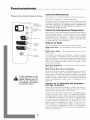
For additional questions please call:
1-866-MAYTAG- 1
or e-maih
customerservice@maytagair, com
@
@
@
@
@
@
@
Keep
@
@
@
@
@
@
@
@
@
@
@
@
@@@@@@@@@@@@@@@@@@@@@@@@@@@@@@@@@@@@@@@@@@@@@@@@@@@@@
these instructions for future reference

Important Safety Instructions ooooooooooooooooooooooo
Electrical Shock Hazard
1. Plug unit only into grounded electrical outlet,
2. Do not use an extension cord or plug adapter with this unit,
3. Do not operate unit with front removed,
Failure to follow the above precautions could result in electrical
shock, fire or personal injury.
If the air conditioner has a serial plate rating of 11S volts and greater
than 7.5 amps it must have its own fuse or circuit breaker, and no
other device or unit should be operated on that fuse or circuit breaker.
If the air conditioner has a serial plate rating of 230 volts it must
have its own fuse or circuit breaker, and no other device or unit
should be operated on that fuse or circuit breaker.
The location of the serial plate that applies to this inodel can be
found on the back page of this manual.
Notice: Do not
operate this air
conditioner
without proper
time delay cir-
cuit protection.
Refer to serial
plate for proper
power supply
requireInents.
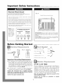
RECOMMENDED CIRCUIT WIRE SIZES
(As hlstalled per blfildi_l,¢ co&)
PROTECTOR SIZE WIRE GAUGE
1S AMP #14 MINIMUM
20 AMP #12 MINIMUM
30 AMP # 10 MINIMUM
@©©@
115V 230V 230V 230V
15.4 15.4 20A 30A
Hgo A
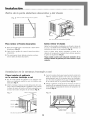
Expanded Polystyrene (gray/white tbam)
Pictured air
conditioner is similar to your air conditioner:
Product Damage: Do not cut, alter or remove any of the expand-
ed polystyrene (gray/white foam) inside this air conditioner
(Fig. AL THE WHITE FOAM IS PART OF THE UNIT, NOT PACKING
MATERIAL,
For Your Safety: Do not store or use gasoline or other flaInmable
vapors and liquids in the vicinity of this or any other appliance. The
fumes can create a fire hazard or explosion.
Before Getting Started °°° °°°°°°°°°°°°°°°°°°°°°°°°°o
Electrical Requ[yements
_o _ Single outlet
_#rolmdin_#wall
Important Grounding Requirements
1. Air conditioner has a three-prong grounding plug on
power supply cord, which must be plugged into prop-
erly grounded three-prong wall receptacle for your pro-
tection against possible shock hazard. For models up to
and including 7.5 amperes use grounding type wall
receptacle to match cord plug (Fig. B).
2. For models above 7.5 amperes use single outlet ground-
ing type wall receptacle to match cord plug (Fig. C).
Caution: We recommend that a qualified electrician
install unit in accordance with the National Electrical
Code and local codes and ordinances.
Caution: Use copper conductors only.
j
• Upholsterers' tacks "_ j _-_ • Knifi" A ,/
c_
• Hex driver) ratchet or wrench _,_
Window Requ[rements
27 718" to 40" Wide
This air conditioner is factory prepared for installation in
standard double-hung windows with actual opening
width of 27 7/8" to 40" and clear, vertical opening of 18"
minimum from bottom of sash to sill. Unit can be
installed in a 26 3/4" wide window, if cabinet side seals are
removed. Use foam seal to fill any openings between the
sides of the cabinet and the window stop molding.
Note: All supporting parts should be secured to firm
wood, masonry or metal
Caution: Do not block air circulation to outside
louvers of cabinet.

Installation°°°°°°°°°°°°°°°°°°°°°°°°°°°°°°°°°°°°°°°°°°°°°°°°
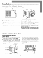
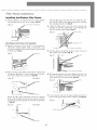
Decoraffve & ChassT RemovM
Ffgo D Rernove screw fivrn both sides of cabinet Ffgo E
Cabinet Chassis
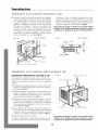
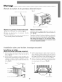
Decorative Front Removal
1. Remove the phillips screws on both sides of the cabinet
(Fig. D).
2. Remove control knobs (if unit has mechanical contols).
3. Gently pull forward while grasping both sides of the
decorative front.
Rel,17ove
screw f!_om both sides of cabinet
Removing the Chassis
Remove the two (2) antitheft screws from the bottom
front side of the cabinet. RETAIN THESE SCREWS, they
will be replaced later in the installation (Fig. E).
Slide the chassis out of the cabinet by grasping the front
flange of the evaporator cover and pulling forward while
bracing the cabinet (Fig. E).
Use caution when working around exposed sharp edges
of the cabinet and sharp coils to avoid injury or torn
clothing.
Window f staffaffon (Hash Moun#
Installing Cabinet in Window
(Flush Mount)
1. Attach cabinet side seals to the existing holes in the
cabinet using the six (6) screws supplied (Fig. F).
2. Open window and mark the center of window sill.
Carefully place cabinet in window and align center
mark on the bottom tie bar with the center mark on
the window sill (Fig. F).
Slider
Cabinet
SCI'OWS
Cabinet side seal Bottom tie bar
3. Close window until it touches behind top retainer bar.
Do not close window so tightly that sliders cannot
move. (Do not release your grip on the cabinet until
the lower window sash is in its final position) (Fig. F).
4. Attach the cabinet to the window sill by driving two (2)
1" long screws through each cabinet track into the win-
dow sill (Fig. G).
Ffgo G
1" long
145mlow sill
2

Installation°°°°°°°°°°°°°°°°°°°°°°°°°°°°°°°°°°°°°°°°°°°°°°°°°°°°
Wi dew l staHade FHush Meu t)
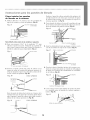
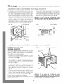
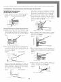
5. Brackets may be attached to cabinet in either direction
for maximum support, depending on the depth of the
window sill. Place the leveling bracket with leveling
bolt under cabinet and attach to the cabinet with two
(2) #8 screws. Tighten screws through cabinet into the
smaller holes in the bracket. Placement of bracket and
screws to slots on cabinet track will depend on size of
the window sill. Position the brackets so bolts will rest
securely on window sill (Fig. H).
Be sure cabinet maintains an outward pitch. Air condi-
tioner should slant slightly downward on the outside
as shown by 1/2 a bubble off on a carpenter's level. This
outward pitch prevents water from entering the room
(Fig. I).
Caution: Do not drill a hole in bottom pan. Unit is
designed to operate with approximately 1/2" of water in
bottom pan.
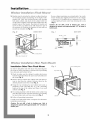
F@o N INSIDE VIEW Fdgo 5 SIDE VIEW
#8 SCI'CWS
Cabinet track
Sill e_qe Screw
1 1/4"_
SpaCC
I/4"
® .........
Cabinet
Ira&
bolt
Outer edge of window sill
Leveli1_q bracket
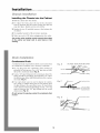
Wfndow dnstaHadon (Non Hush Moun }
Installation OtherThan Flush Mount
In order to install the unit with more of it projecting into
the room, it will be necessary to relocate the top retaining
bar, side seals and bottom tie bar.
1. Check to make sure the cabinet's outside side louvers
will not be blocked when the unit is moved farther into
the room (Fig. d).
2. Remove the top retainer bar, cabinet side seals and bot-
tom tie bar from the cabinet. Relocate them for the
desired projection into the room (Fig. d).
3. Using the top retaining bar and cabinet side seals as
templates, locate and drill five (S) 7/32" mounting
holes on the top of the cabinet and three (3) on each
cabinet side (Fig. J).
4. Use sealing material to fill the holes in the cabinet top
and sides that become exposed when the top retaining
bar and cabinet side seals were relocated (Fig. J).
5. Follow all preceding instructions.
Consult your authorized dealer or importer for alternative
installation instructions.
Caution: Do not drill a hole in bottom pan. Unit is
designed to operate with approximately 1/2" of water in
bottom pan.
Fdgo d
T(Q retainerbar
7/32" mounting boles
Bottom tie bar
3

@@@@@@@@@@@@@@@@@@@@@@@@@@@@@@@@@@@@@@@@@@@@@@@@@@@@@@@@@@@@@@@@@@@
Ffffer P3 el I s Mf3ffo
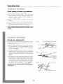
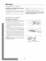
Installing the Window Filler Panels
1. Measure distance "X" between the face of the window
stop molding and the side of the cabinet (Fig. K).
F_ K Face o[ window stop molding
Side of cabindt
Note: Measure both sides of unit separately.
2. Subtract one groove (3/16") from "X" measurement to
obtain the required width, Using a sharp knife, score
the groove until the filler panel becomes weak enough
to break apart (Fig. L).
F_o L Filh, rpanel
Slide the filler panel out from the air conditioner cabi-
net until the filler panel flange contacts the window
stop molding (position 3) (Fig. NL
4. Attach the filler panel to the face of the window stop
molding by driving upholsterers' tacks through the
holes in the filler panel flange (Fig. OL
Fills,r pane1711111111lil lll_Face of-window stop rooMing
5. Pull the sliders out until the sliders contact the face of
the window stop molding (Fig. P).
F_o _ Hole in slider Slider
"X" minus one 2¢roove(3/16")
3. Insert cut edge of the filler panel into the cabinet side
seal groove (position 1). Leave a small space at the bot-
tom of the cabinet side seal groove (Fig. M).
F_go M TOP VIEW
Face of window stop rooMing
6. Pull bottom window sash down tightly and lock it in
place by installing a 5/8" long screw through the hole
in the slider into the window sash (Fig. OL
Figo @ Slid(..
145udow stop molding€
Rotate the filler panel backward toward the window
frame until the filler panel clears the window sill. Push
the filler panel down against the window sill (position
2) (Fig. N).
F_. _ Position 3 TOP VIEW
v_
my"
5/8" long screw
7. Cut the plastic foam seal to proper length and insert it
between the upper and the lower window sash (Fig. R).
F_go R
Plastic Foam Seal
\\\
\
4

Installation°°°°°°°°°°°°°°°°°°°°°°°°°°°°°°°°°°°°°°°°°°°°°°°°°°°°
Chassfs f s affado
Installing the Chassis into the Cabinet
1. Slide the chassis into the cabinet.
2. To replace the front, place the top of the decorative
front in position and pivot back towards the unit and
snap into place. Replace screws and air filter.
3. Replace the two (2) antitheft screws at the bottom side
of cabinet.
4. Use supplied sealant to fill any minor openings.
5. Make sure unit is OFF, before plugging into the outlet.
Use caution when working around exposed sharp edges
of the cabinet and sharp coils to avoid injury or torn
clothing.
Drafn Instalfadon
Condensate Drain
A condensate drain is provided to divert excess water when
air conditioner is installed over a doorway or sidewalk.
1. Pry cap plug from the condensate drain (located on
underside of bottom pan). Use a 3/8" pipe tap and fully
thread the condensate drain (Fig. S).
2. Screw a 3/8" pipe fitting into the condensate drain. The
fitting should be protruding approximately 1/2" above
the bottom pan when fully threaded into the conden-
sate drain (Fig. T).
3. If an open drain source is used to dispose of conden-
sate, plastic or rubber tubing may be run directly from
the pipe fitting to the open drain source. If closed drain
source (internal structural plumbing) is used, a "P" trap
must be between the 3/8" pipe fitting and the closed
drain source (Fig. U).
Do not remove the cap plug, unless the condensate drain
is used.
OUTSIDE VIEW FROM BOTTOM
_o [J To closed drain source
P ,,p. trat)
5

@@@@@@@@@@@@@@@@@@@@@@@@@@@@@@@@@@@@@@@@@@@@@@@@@@@@@@@@@@@@@@@@@@@
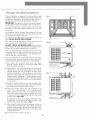
T rougho heoWaff I s affado
This air conditioner is designed as a slide-out type chassis,
making it possible to install it through-the-wall in both exist-
ing and new construction. We recommend that this type of
installation be performed with professional assistance.
IMPORTANT: This appliance must be installed according to
all applicable electrical and building codes and ordinances.
It is recommended that you have help to install your unit
and that you use proper lifting technique to avoid per-
sonal injury.
It is important that you inspect the condition of the wall
where the air conditioner will be installed. Be sure the wall
can support the weight of the unit.
All cabinet louvers MUST BE on the outdoor side of the
wall. DO NOT BLOCK SIDE LOUVERS.
The cabinet must be installed level from side-to-side and
with a downward tilt from inside to outside.
DO NOT USE AN EXTENSION CORD: Make certain a
proper electrically sized wall receptacle is available close to
the unit. If not, make arrangements to install one.
If the air conditioner has a serial plate rating of 115 volts
and greater than 7.5 amps it must have its own fuse or cir-
cuit breaker, and no other device or unit should be oper-
ated on that fuse or circuit breaker.
If the air conditioner has a serial plate rating of 230 volts it
must have its own fuse or circuit breaker, and no other device
or unit should be operated on that fuse or circuit breaker.
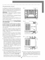
1. First remove the Decorative front panel and chassis
from the cabinet. Remove top and side retainer bars
from the cabinet (see page 2).
2. Determine the size of the opening for a wood frame by
adding 1/8" to the width and height of the cabinet.
Measure height from top of cabinet to bottom of bar.
Add this measurement to the thickness of wood used to
build the frame. This will determine the size of wall
opening needed. Minimum 1" thick lumber is recom-
mended when building the frame. When determining
finish frame thickness, be sure not to cover side louvers
on the cabinet.
3. Install the finished frame in the wall opening square
and level, nail or screw it securely to the wall and place
the cabinet into the framed wall opening.
4. Make sure cabinet projects into the roomside of the
wall 1 1/4" at the top and 1 1/2" at the bottom to
ensure proper tilt and access to the anti-theft screw,
then fasten cabinet to the frame by drilling twelve (12)
1" wood screws (not supplied) through the cabinet and
into the frame (Fig V & W).
If installation is made in a building with brick veneer
construction, a steel angle lintel must be used to sup-
port the bricks above the cabinet (Fig XL
5. After cabinet is installed caulk all openings, inside and
outside between finish frame and cabinet to prevent
moisture from getting to the interior of the wall. Use of
flashing (driprail) will further prevent water from drip-
ping inside the wall.
6. Install chassis into cabinet (see page 5).
6
(12) 1" wood screws
Fd_ _ Interior trim
Caulk top, bottom and two sides
Ddcorativc
fi'ont panel _
Anti-theft screw
Do not block sMe louvers of cabinet
Minimum 1
support (nailed or
screwed to wood fi'ame)
2" wood fi'ame all around
Flashin
Caulkin,¢ (bel-weeu
bottom rail and flashing
Cabinet
1/2"
S]D_TCd
1/2"
SpfICC

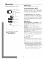
Operation°°°°°°°°°°°°°°°°°°°°°°°°°°°°°°°°°°°°°°°°°°°°°°°°°°
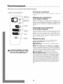
Power Control
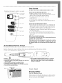
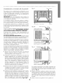
E_eC_rO_fC CO_rO_ Pa_e_ Tile Power Control turns tile unit on and off.
Set Temperature/
Timer Distflay
Temperatm'e/Timer
Hour Controls
TIIllCI' Colltrol
Fan Speed
Control
Mode Control
-- Power Control
_ he heat from this unit is designed
only as a supplemental heat
source in addition to
regular heating systems.
Set Temperature/Timer Display
Shows the set temperature when the unit is in operation
and hours when the timer is being set. THE TEMPERA-
TURE DISPLAY ONLY SHOWS THE SET TEMPERATURE,
NOT THE ACTUAL ROOM TEMPERATURE.
Temperature/Timer Hour Controls
These buttons are used to raise or lower the set tempera-
ture in increments of 1° from 66 ° to 88 °. By depressing
both buttons at once, the display will toggle between
Celsius and Fahrenheit. When the timer is being set, these
buttons are used to change the hour setting in increments
of 1 from 00 to 24.
Mode Control
The Mode Control has three settings: Fan, Cool,
Heat, and Energy Saver. A green light will indicate which
mode is currently being utilized.
Cool Mode - The unit will circulate and cool the air.
Fan Mode - The unit will only circulate the air.
Heat Mode - The unit will circulate and heat the air.
Heater Safety Feature- When heater is powered off, low fan
will automatically stay on and run for 60 seconds to
ensure the removal of residual heat, meanwhile, the Low
Fan LED blinks until the low fan stops.
I=nergy Save Mode - The fan will switch from the set
fan speed to Low whenever the compressor turns off in
response to the thermostat. When the compressor cycles
back on, the unit will return to the original fan setting.
Fan Speed Control
High, Low, and Auto
The settings are adjusted with the Fan Speed Control, each
time the button is depressed it changes the setting. A
green light will indicate which setting is currently being
used.
When the Auto feature is selected while the air condition-
er is in the Cool or Heat mode, the fan speeds will change
automatically as the temperature in the room changes.
In Cool Mode when the room reaches 7 ° or more
above the set temperature High Fan will be used, 7° or
less above the set temperature will use Low fan.
In Heat Mode when the room reaches 7° or more
below the set temperature High fan will be used, 7 ° or
less below the set temperature will use Low fan.
7

@@@@@@@@@@@@@@@@@@@@@@@@@@@@@@@@@@@@@@@@@@@@@@@@@@@@@@@@@@@@@@@
Tile pictured control panel is similar to your panel
@
Set Temperature/
Timer i)isph_y
Temperature/Timer
Hour Controls
Timer Control
The timer can be set to either turn the unit on or off.
To turn the unit ON using theTimer:
• Depress the timer key when the power is off, the
display will read 00. Adjust to the desired number of hours
before TURN ON using the up/down arrows.
• The display will show the time by hours left
until TURN ON.
• To turn the timer off, depress the timer key.
• A green light next to the Timer Control indicates that the
timer is set.
Fan Speed
Control
-- Mode ContTvl
To turn the unit OFF using theTimer.
• Depress the timer key when the power is on, the display will
read 00. Adjust to the desired number of hours before TURN
OFF using the up/down arrows. The display will automatical-
ly go back to the set temperature after 10 seconds.
• To display the amount of time left until TURN OFF, depress
the timer button once.
• To turn the TIMER OFF, depress the timer button twice.
• A green light next to the Timer Control indicates that the
timer is set.
Built-in three minute timing delay.
This electronic controlled unit will not automatically resume
operation after a power failure.
ff this electric unit will not respond to touch pad or remote
control commands, it is necessary to unplug the unit from
the electrical outlet for five seconds and then plug the unit
back in.
Air Conditioner Remote Control
The functions work the same as your air conditioner's touch controls.
Batteries: Remove the cover on the back of the remote controller and insert the batteries with the
(+) and (-) poles pointing in the proper direction.
CAUTION:
• Use only AAA or IEC R03 1.5V batteries.
• Remove the batteries if the remote controller is not used for a
month or longer.
• Do not attempt to recharge the supplied batteries
• All batteries should be replaced at the same time.
• Do not dispose of the batteries in a fire as they may explode.
• Do not mix old and new batteries.
• Do not install the batteries with the polarity (+/-) reversed.
• Keep batteries and other things that could be swallowed
away from young children. Contact a doctor immediately if
an object is swallowed.
Fdgo d
Adjustable louvers
P3 el
Directing Airflow
(Unit with adjustable louvers)
Unit is engineered with adjustable louvers to direct discharge
airflow. Louvers are manually adjusted by moving levers in
direction of desired airflow (Fig. J).
8

Maintenance°°°°°°°°°°°°°°°
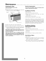
Cleaning Air Filter
EVERY TWO WEEKS: Clean the filter.
1. Turn power off.
2. Remove the air filter by grasping the top corners and
pulling it up and out of the unit (Fig. Z).
F_ Z Adjustabh' Louvers Air Filter
Decorative Front
3. Wash in hot soapy water, rinse and shake dry.
4. Replace the filter, with the front of the filter toward you.
5. To dry the filter thoroughly, run your unit for a few
minutes. Remember, only a clean filter works properly
and delivers top efficiency at every setting.
Note: Failure to keep air filter clean will result in poor air
circulation. DO NOT operate without filter. This can ren-
der the unit inoperative.
Proper use and care of your air conditioner will help
ensure longer life of the unit. It is recommended to annu-
ally inspect and clean the coils and condensate water
passages. Expense of annual inspection is the con-
sumers" responsibilities.
0000000000000000000000000000000
Service Instructions
To save time and expense, check the following before
calling an authorized service station.
Insufficient Cooling
V"Turn power off.
V"Shut all windows and doors in room.
V"Remove any obstructions from inside and
cabinet louvers.
V"Inspect filter and clean if dirty.
V"Turn Thermostat and Mode to coolest settings.
outside
Under certain conditions the cooling coils directly behind
the filter, may ice up and block the airflow. This is a com-
mon occurrence in air conditioners caused when the outside
temperature drops below 70°F (21°C) while the humidity
remains high. If this happens, simply turn the unit off and
allow the ice to melt, then resume normal operation.
Insufficient Heating -
Heating Models Only
V"Turn unit off.
V"Shut all windows and doors in room.
V"Remove any obstructions from inside and outside cabi-
net louvers.
1" Close Vent.
1" Turn Thermostat to Warmer and Mode to HEAT.
Unit Fails to Start
1" Turn unit off.
1" Replug line cord plug into outlet to be sure electrical
contact is being made. (If firm contact is not being
made, outlet may have to be replaced).
1" Turn Master Control to HI FAN. If air circulating fan
does not operate, check house circuit breaker (or fuses).
9

Warrantyoooooooooooooooooooo
For Models Installed
in North America - If Service
or Parts are Required
First, make the recommended checks. If it appears that ser-
vice or parts are still required, see your room air condition-
er warranty "How to Obtain Warranty Service or Parts".
For Models Installed
Outside North America
For room air conditioners purchased for use outside North
America, the manufacturer does not extend any warranty
either expressed or implied. Consult your local dealer for
any warranty terms extended by the importer in your
country.
Room Air Conditioner Warranty
(Within the 48 contiguous United States, state of Hawaii,
the District of Columbia, Puerto Rico and Canada)
Full (FiveYear) Parts and Labor Warranty
During the five years after the date of original purchase,
Fedders North America will, through its authorized ser-
vicers and free of charge to the owner or any subsequent
user, repair or replace any parts which are defective in
material or workmanship due to normal use. Ready access
to the air conditioner is the responsibility of the owner.
Note: In the event of any required parts replacement with-
in the period of this warranty, Fedders North America
replacement parts shall be used and will be warranted
only for the period remaining on the original warranty.
Exceptions
The above warranty does not cover failure to function
caused by damage to the unit while in your possession
(other than damage caused by defect or malfunction), or
by its improper installation, or by unreasonable use of the
unit, including without limitation, failure to provide rea-
sonable and necessary maintenance or to follow the writ-
ten Installation and Operating Instructions. If the unit is
put to commercial, business, rental, or other use or appli-
cation other than for consumer use, we make no war-
ranties, express or implied, including but not limited to,
any implied warranty of merchantability or fitness for par-
ticular use or purpose.
O@O@O@O@O@O@O@O@O@O@O@O@O@O@O@O
THE REMEDIES PROVIDED FOR IN THE ABOVE EXPRESS
WARRANTY ARE THE SOLE AND EXCLUSIVE REMEDIES
THEREFOR, NO OTHER EXPRESS WARRANTIES ARE
MADE. ALL IMPLIED WARRANTIES, INCLUDING BUT NOT
LIMITED TO ANY IMPLIED WARRANTY OF MER-
CHANTABILITY OR FITNESS FOR A PARTICULAR USE OR
PURPOSE, ARE LIMITED IN DURATION TO FIVE YEARS
FROM THE DATE OF ORI(;INAL PURCHASE. IN NO EVENT
SHALL FEDDERS NORTH AMERICA BE LIABLE FOR INDI-
RECT, INCIDENTAL, OR CONSEQUENTIAL DAMAGES,
EVEN IF ADVISED IN ADVANCE OF THE POSSIBILITY OF
SUCH DAMAGES. NO WARRANTIES, EXPRESS OR
IMPLIED, ARE MADE TO ANY BUYER UPON RESALE.
Some states do not allow limitations on how long an
implied warranty lasts or do not allow the exclusion or
limitation of incidental or consequential damages, so the
above limitations or exclusions may not apply to you.
This warranty gives you specific legal rights, and you may
also have other rights which may vary from state to state.
No warranties are made for units sold outside of the above
stated areas. Your distributor or final seller may provide a
warranty on units sold outside of these areas.
How to Obtain
Warranty Service or Parts
Service for your room air conditioner will be provided by
CareCo, a division of the manufacturer with authorized
independent CareCo servicers nationwide.
Note: Before calling for service, carefully read the
Installation and Operating Instructions booklet. Then if
you need service:
1. Call a CareCo authorized servicer and advise them of
model number, serial number, date of purchase and
nature of complaint. Service will be provided during
normal working hours. Contact your dealer for the
name of an authorized servicer if unknown to you.
2. If your dealer is unable to give you the name of a ser-
vicer or if you need other assistance, call the following
toll-free number for the name of an authorized servicer
or authorized parts distributor:
1-866-MAYTAG 1
or you may write:
CareCo, Service Department
415 W. Wabash Ave., RO. Box 200
Effingham, IL 62401
Proof of Purchase Date
It is the responsibility of the consumer to establish the
original purchase date for warranty purposes. We recom-
mend that a bill of sale, cancelled check, or some other
appropriate payment record be kept for that purpose.
10

Instrucciones importantes de seguridadoooooooooo
Peligro de descarga el6ctrica
1. Enchufe la unidad en till tonlacorriente con conexi(m a tierra.
2. No use un cable de extensi6n ni un adaptador de enchufe con este
aparato,
3. No 1o haga funcionar sin la cubierta delantera.
El no seguir las precauciones enumeradas anteriornmnte podria
causar descargas el0ctricas, incendio o lesiones personales,
Si el acondicionador de aim trae en la placa una clasificaci6n de 11S
voltios y ross de 7.S amperios, entonces debe ir conectado a su pro-
pio fusible o cortacircuitos y ningfm otro aparato o unidad se podr5
conectar a dicho fusible o cortacircuitos,
Si el acondicionador de aire trae en la placa una clasificaci6n de 230
voltios, entonces deber_ ir conectado a su propio fusible o cortacir-
cuitos y ningfin otro aparato o unidad se podr_ conectar a dicho
fusible o cortacircuitos.
La ubicaci6n de la placa en 0ste modelo se encuentra indicada en la
filtima p,_gina de Oste manual,
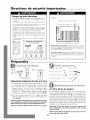
Aviso: No haga
funcionar estre
aire acondi-
cionado sin un
circuito tempo-
rizador que
brinde la protec-
cidn adecuada.
En la placa de
identificaci6n
aparecen los req-
uisitos correctos
de alilnentaci6n,
TAIVIAI_IOS RECOMENDADOS PARA LOS
ALAMBRES DEL CIRCUITO
(I*>stalados('ggmlosn'glame*_tosdeco*_strI*dci&_)
TAMAI_O DEL CALIBRE DEL
PROTECTOR ALAMBRE
15 AMP #14 MINIM°
20 AMP #12 MINIMO
O) AMP #10 MINIMO
@©©@
115V 230V 230V 230V
16A 16A 20A 30A
E_go A
Poliestireno ey[)andido (Es])llllltl _{ris/blanca)
El aire acomiicionado de 1¢1fi_to es similar ¢11szlyo.
Dafio al producto: No corte, altere o retire ningdI1 pedazo de poli-
estireno expandido (espuma gris/blanca) que se encuentre dentro del
acondicionador de aim (Fig. AL EL POLIESTIRENO EXPANDIDO
FORMA PARTEDE LAUNIDAD, NO ES MATERIAL DE EMBALAJE,
Para su seguridad: No ahnacene ni utilice gasolina u otros vapores
y liquidos inflamables cerca de este artefacto o de cualquier otro arte-
facto, Los vapores pueden provocar un incendio o una explosi6n,
Antes de empezaroooooooooo ooooooooooooooooooooooooooo
de tmesta a tierra
Requistos importantes
para la conexi6n a tierra
1. E1 equipo de aire acondicionado tiene en el cord6n de
corriente un enchufe a tierra de tres puntas, el cual debe
set introducido en un tomacorriente de tres puntas
debidamente conectado a tierra para protecci6n contra
posibles descargas el_ctricos. Para modelos de hasta 7.5
amperios utilice un tipo de tomacorriente con conexi6n
a tierra, adecuado para el enchufe del equipo (Fig. B).
2. Para modelos de mils de 7.S amperios, utilice un tomacor-
riente con conexi6n a tierra para un solo enchufe (Fig.¢).
Precaucion: Recomendamos que un electricista calificado
instale la unidad de acuerdo alas normas electicas
nacionales y las normas y regulaciones locales.
Precaucion: Utilice solamente conductores de cobre.
11
Heryam[entaa neceaadaa
• Destornillador comdn /
/
• R<2¢lao cinta m(,trica '_Z
• Conexi6n de tubo de 3/8 de/ml X
• Tachuelas para tapicer& _ _-_
• Martillo
• Nivel
• Taladro _
• Cuchill(i J
• DestornilladoT; llave o matraca hexagonales !_...
Requ[sYtoa de fa ventana
27 7/8 a 40 pulgadas
E1acondicionador de aire se prepara en la f_brica para una
instalaci6n est_ndar en ventanas de guillotina con una
abertura a lo ancho de 27 7/8 a 40 pulgadas de ancho y 18
pulgadas de altura minima desde el bastidor inferior hasta
el quicio de la ventana. La unidad puede instalarse en una
ventana de 26 3/4 pulgadas de ancho, si se retiran los sel-
ladores laterales del gabinete. Utilice sellador de espuma
de goma para llenar las aberturas entre los lados del gabi-
nete y la moldura de tope de la ventana.
Nota: Todaslas piezas de apoyo deberan asegurarse a
madera, material de albafiileria o metal firme.
Precaucion:No bloquee la circulaciondel aire de las rejil-
las exteriores del gabinete.

Instalaci6n oooooooooooooooooooooooooooooooooooooooooooooooo
Q
Gabinete
Retire los tornillo de ambos lados del gabinete
Chasis
Para retirar el frente decorativo
1. Retire los tornillos que se encuentran a ambos lados
del gabinete (Fig. D).
2. Quite las dos perillas de control (control mecfinico
solamente).
3. Tire suavemente hacia adelante mientras sostiene
los dos lados del frente decorativo.
C6mo retirar el chasis
Quitar los dos tornillos, localizados en el fondo y frente de
la careta. GUARDE ESTOS TORNILLOS, ellos deberfin set
colocados de nuevo en la instalaci6n (Fig. E).
Corra el chasis hacia afuera sujetando el frente de la
cubierta del evaporador y halando hacia delante mientras
se apoya en el gabinete (Fig. E).
Tenga cuidado cuando este trabajando alrededor de las
esquinas afiladas del gabinete para evitar heridas o ropas
rasgadas.
C6mo instalar el gabinete
en la ventana (montaje a ras)
1. Fije los sellos lateral del gabinete a los agujeros exis-
tentes en el gabinete usando los seis (6) tornillos sum-
inistrados (Fig. F).
2. Abrir la ventana y marcar el centro del quicio de la ven-
tana. Colocar cuidadosamente el gabinete en la ventana
y alinear la marca del centro en la barra separadora con
la marca del centro del quicio de la ventana (Fig. F).
3. Cerrar la ventana hasta que toque la parte de atrfis de la
barra de retencidn superior. No cerrar la ventana tan
apretadamente que no se puedan mover las deslizado-
ras. (No soltar el gabinete hasta que el bastidor inferior
de la ventana est_ en su posicidn final) (Fig. F).
4. Monte el gabinete al antepecho de ventana con dos (2)
tornillos de una pulgada insertados a trav6s de cada car-
ril del gabinete asegurfindolos dentro del antepecho de
ventana (Fig. G).
F_o _ Barra tle retemri61tsuperior
Deslizadora
Gabinete
Tornillos
Sello lateral del2(abinete
%Tonullo & zlna/
OJlicio de a venrtana
12

Instalaci6n oooooooooooooooooooooooooooooooooooooooooooooooo
5. Se puede acoplar los soportes al gabinete en cualquier
direcci6n para lograr un mfiximo apoyo, dependiendo
de la profundidad de la repisa de la ventana. Coloque
el soporte nivelador con el perno nivelador debajo del
gabinete y ac6plelos al gabinete con dos (2) tornillos
#8. Apriete los tornillos a trav_s de los orificios mils
pequehos en el soporte. La colocaci6n del soporte y los
tornillos en el riel del gabinete dependerfi del tamaho
de la repisa de la ventana. Coloque los soportes de tal
manera que los pernos niveladores se apoyen firme-
mente en la repisa de la ventana (Fig.H).
Cerci6rese de que el gabinete mantenga una incli-
naci6n hacia afuera. E1 acondicionador de aire deberfi
inclinarse ligeramente hacia el exterior usando la indi-
caci6n de un nivel de carpintero. Dicha inclinaci6n evi-
tarfi que el agua entre en la habitaci6n (Fig. I).
Precaucidn: No perfore un orificio en la bandeja inferior.
El dise_o de la unidad permite que funcione con aproxi-
madamente 1/2 pulgada de agua en la bandeja inferior.
Ffgo N VISTA INTERIOR Ffgo 5 VISTA LATERAL
Tornillos
#8
Borde de Tornillo
la repisa
i/4 _
®1
Rid del
,gabinete
Bol'dC ¢xtcl'ior d(" Ja l'('pisa de! la v(,lltal'la
Instalaci6n diferente al montaje a ras
Para instalar la unidad de modo que se proyecte en la
habitaci6n, serfi necesario reubicar la barra de retenci6n
superior, los selladores laterales, y la barra de separaci6n
inferior.
1. Verifique que las rejillas laterales de la parte exterior del
gabinete no queden bloqueadas al colocar la unidad en
la habitaci6n (Fig. J).
2. Retire del gabinete la barra de retenci6n superior, los
selladores laterales del gabinete y la barra separadora
inferior. Reubiquelos hastaencontrar la proyecci6n
deseada dentro de la habitaci6n (Fig. J).
3. Utilizando la barra de retenci6n superior y los sell-
adores laterales del gabinete como plantillas, ubique y
perfore cinco (S) oriflcios de montaje de 7/32 pulgada
en la parte superior del gabinete y tres (3) en cada costa-
do del gabinete (Fig.J).
4. Utilice material de sellar para llenar los orificios de la
parte superior y de los lados del gabinete que quedaron
expuestos cuando se reubicaron la barra de retenci6n
superior y los selladores laterales del gabinete (Fig. J).
5. Siga las instrucciones precedentes.
Consulte al distribuidor o importador autorizado en caso
de necesitar instrucciones para instalaciones alternativas.
Ffgo J Orificios de montajo de 7/32"
Gabinete Barra
Precaucion: No perfore un orificio en la bandeja inferior.
El dise_o de la unidad permite que funcione con aproxi-
madamente 1/2 pulgada de agua en la bandeja inferior.
13

@@@@@@@@@@@@@@@@@@@@@@@@@@@@@@@@@@@@@@@@@@@@@@@@@@@@@@@@@@@@@@@
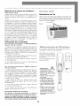
C6mo instalar los paneles
de lienado en la ventana
1. Medir la distancia "X" entre la cara de la moldura de
tope de la ventana y el lado del gabinete (Fig. KL
_ _ Cara de la mohhn'a de tope
de la ventana
Lado del ,_abhwte
Nora: IVledirambos lados de la unidad per separado°
2. Reste una muesca (3/16") de la medici6n "X" para
obtener el ancho necesario. Utilizando un cuchillo aft-
lado, raspe la muesca hasta que el panel de llenado se
debilite lo suficiente para desprenderlo (Fig. I-L
F_ L Panel de relleno
Deslizar el panel de relleno sacfindolo del gabinete del
acondicionador de aire hasta que el reborde del panel
de relleno haga contacto con la moldura de tope de la
ventana (posici6n 3) (Fig. N).
Unir el panel de relleno a la cara de la moldura de tope
de la ventana clavando tachuelas de tapicero en los ori-
ficios del reborde del panel de relleno (Fig OL
Figo 0 _ _ °riOci(':l'_rff"
5. Sacar las deslizadoras hasta que hagan contacto con la
cara de la moldura de tope de la ventana (Fig. PL
_o _ Orificio en deslizadora Deslizadora
"X" menos um_ ranura (3/16 pulgada)
a. Insertar el borde cortado del panel de relleno en la
ranura de sellar del costado del gabinete (posici6n 1).
Dejar un peque_o espacio en la base de la ranura de sel-
lar del costado del gabinete (Fig. M).
F_go M VISTA SUPERIOR
Cara de la moldura de tope de
6. Tirar hacia abajo el bastidor inferior de la ventana y tra-
barlo en su lugar instalando un tornillo de 5/8 pulgada
de largo por el orificio de la deslizadora en el bastidor
de la ventana (Fig. QL
Mohlm'a de tope tle la ventana
Rotar el panel de relleno hacia atrfis en el marco de la
ventana hasta que el quicio de la ventana quede despe-
jado. Empujar el panel de relleno hacia abajo contra el
alf4izar de la ventana (posicidn 2) (Fig. N).
F_go N I'osici6,3 VISTA SUPERIOR
Tornillo de 5/8 pulgada de lat_o
7. Corte el largo correcto del sellador de espuma de plfisti-
co e ins4rtelo entre el bastidor de ventana superior e
inferior (Fig. R).
Hgo
\\\
\ \
Sellador de estmma de pldstico
v_
Posicifn 2 14

Instalaci6n oooooooooooooooooooooooooooooooooooooooooooooooo
Instafadon de1 chasfs
C6mo instalar el chasis en el gabinete
1. Corra el chasis hacia dentro del gabinete.
2. Para reemplazar el frente, coloque la parte superior del
panel decorativo en posicidn y gire hacia atrfis en direc-
cidn a la unidad y coloque en sitio. Reemplace los
tornillos y el filtro de aire.
3. Vuelva a colocar los dos (2) tornillos en el rondo del
gabinete.
4. Usar el sellador provddo para llenar pequehas aberturas.
5. Asegfirese que la unidad estfi en OFF, osea desconecta-
da, antes de conectar la unidad a la corriente.
Tenga cuidado cuando este trabajando alrededor de las
esquinas afiladas del gabinete para evitar heridas o ropas
rasgadas.
Instafadon de1 drena]e
Drenaje de condensaci6n
Se proporciona un drenaje de condensaciOn para desviar
el agua excesiva cuando el acondicionador de aire se insta-
la sobre una puerta o acera.
1. Separar el tapdn del drenaje de condensacidn (ubicado
en la parte inferior de la bandeja). Utilizar un conector
de tubo de 3/8" y enroscar completamente el drenaje de
condensacidn (Fig. S).
2. Atornillar un ajuste de tubo de 3/8" en el drenaje de
condensacidn. E1 ajuste deberfi sobresalir aproximada-
mente 1/2" sobre la bandeja inferior cuando estO com-
pletamente enroscado en el drenaje de condensacidn
(Fig. T).
3. Si se utiliza una fuente de drenaje abierta para eliminar
el producto de la condensaciOn, podrfi hacerse pasar un
tubo de plfistico o de goma directamente desde el ajuste
de tubo hasta la fuente de drenaje abierta. Si se utiliza
una fuente de drenaje cerrada (tuberia estructural inter-
na), deberfi haber una trampa "P" entre el ajuste de
tubo de 3/8" y la fuente de drenaje cerrada (Fig. U).
No quitar el tapon a menos que se use el drenaje de
condensado.
F goS
VISTA EXTERIOR DESDE ABAJO
Tapdn
Drenalede
COlldCl2Stlci(_tl
F_go T
Bandeja infbrior Drem@de
CoIld_!IIS_tCiOtl
Ajuste de mbo de
3/8" completamente
enmscada en el
drena]e de
conddnsacidn
_o [J Hacia filente tle drenaje
!2 . Trampa "F"
15

@@@@@@@@@@@@@@@@@@@@@@@@@@@@@@@@@@@@@@@@@@@@@@@@@@@@@@@@@@@@@@@
Este aparato de aire acondicionado estfi disefiado con un
chasis deslizante, lo cual hace posible instalarlo a tray,s de
la pared en edificaciones existentes o en construcciones
nuevas. Recomendamos que este tipo de instalaci6n lo
realice con ayuda profesional.
IMPORTANTE: Este electrodom_stico debe instalarse de
conformidad con todas las ordenanzas y c6digos el4ctricos
y de construcci6n aplicables.
Se recomienda obtener ayuda para instalar su unidad y
que el instalador aplique thcnicas apropiadas para el alza-
do de objetos pesados a fin de evitar lesiones personales.
Es importante inspeccionar la condici6n de la pared
donde se instalarfi el aire acondicionado. Aseghrese de que
la pared tenga capacidad suficiente para soportar el peso
de la unidad.
Todas las ventilas del gabinete deben quedar colocadas en
el lado exterior de la Eared. NO BLOQUEE LAS REJIL-
LAS DE VENTILAClON LATERALES O VENTILAS.
E1 gabinete debe instalarse a nivel horizontalmente de
lado a lado y con una inclinaci6n del frente hacia atrfis
(del interior al exterior).
NO USE EXTENSlONES ELECTRICAS: Aseg0rese de que
haya disponible un tomacorrientes con capacidad apropiada
cerca de la unidad. De lo contrario, instale uno nuevo.
Si la placa del fabricante del aparato de aire acondiciona-
do indica un voltaje nominal de 11S voltios y una corri-
ente mayor de 7,S amperios, serfi necesario instalarlo con
su propio fusible o interruptor automfitico (disyuntor), y
no deberfi conectarse ningfin otro aparato el4ctrico a
dicho fusible o interruptor el4ctrico.
Si la placa del fabricante del aparato de aire acondiciona-
do indica un voltaje nominal de 230 voltios serfi necesario
instalarlo con su propio fusible o interruptor automfitico
(disyuntor), y no deberfi conectarse ningfin otro aparato
el4ctrico a dicho fusible o interruptor el4ctrico.
1. Primero retire el panel frontal decorativo y el chasis del
gabinete. Retire las barras de sujeci6n superior y lat-
erales del gabinete (vdase la p_gina 12).
2. Determine el tamafio de la abertura para el marco de
madera, afiadiendo 1/8" a la anchura y a la altura del
gabinete. Mida la altura desde la parte superior del gabi-
nete hasta la parte inferior de la barra. Afiada esta medi-
das al grosor de la madera utilizada para construir el
marco. Esto determinarfi el tamafio necesario de la
abertura en la pared. Se recomienda usar madera con
un grosor minimo de 1" para construir el marco. A1
determinar el grosor final del marco, asegOrese de no
cubrir las ventilas laterales en el gabinete.
3. Instale el marco de acabado en la abertura de la pared,
y asegOrese de 4ste quede a escuadra y a nivel, clfivelo o
atornillelo para fijarlo a la pared e introduzca el gabi-
nete en la abertura enmarcada en la pared.
4. Aseghrese de que el gabinete se proyecte sobre la super-
ficie de la pared en el interior de la habitaci6n, 1 1/4" de
pulgada en la parte superior y 1 1/2" en la parte inferi-
or, para lograr una inclinaci6n apropiada y acceso al
tornillo de seguridad (antirrobo), a continuaci6n fije el
gabinete al marco, con ayuda de un taladro enrosque
doce (12) tornillos de 1" para madera (no suministra-
dos) a trav4s del gabinete hasta el marco (Fig. V y IN).
(12) tor1#llos de 1" para madera
_ _ Mohlura interior
Calafatee la parte superior;
la parte inferior y los hides
Panel
dccol'atll/O
fi'ontal
Tor1_illo de
sequridad
(¢f;ztirrobo) %
No bloquee las ventilas laterales del gabinete e
Apoyo de madera de
1 .v 6" colllo tHflliIHo (clavado 0
atomillado al de madera
M¢11'C0 dc tH¢tdcI'¢t
Gabinete
I 1/4"
Proyec-
ci6n de
i 1/2"
_o ,_ Revestimient
Dintel de dl_(ulo
Sello de cala
(riel cortagotas)
Calafhteado (entre el riel
inferior y el cubrejtmtas)
cidh de
' 1/4"
Provec-
ci6n de
1/2"
Si se realiza la instalaci6n en un edificio construido con
revestimiento de ladrillo, serfi necesario instalar un din-
tel de fingulo de acero para apoyar los ladrillos sobre el
gabinete (Fig. X).
5. Despu4s de instalar el gabinete calafatee todas las aber-
turas por dentro y por fuera entre el marco de acabado
y el gabinete para evitar que la humedad penetre al
interior de la pared. Instale un cubrejuntas (corta gotas)
para evitar que el agua penetre por goteo al interior de
la pared.
6. Instale el chasis en el gabinete (vdase la p_ina 15).
16

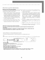
FuncionamientOoooooooooooooooooooooooooooooooooooooooooo
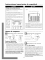
Panel de control elec ydnfco
Pantalla de
c(mf_g.racifn de
tempera_lra/reloj
Controle,s de
tPIHpcl'atlll'a/hol'aS
dereloj
Control de relo]
Control tle
velocidad tle
ve,tilador
i Control
de modo
i Control tle
alimentaci6n
El calor proveniente de este
acondicionador de aire ha sido
disefiado solamente como una
fuente de calor suplementario
y no sustituye a los sistemas
de calefaccibn regulares.
Control de Alimentaci6n
Este bot6n pone en marcha y apaga el acondicionador de aire.
Indicador de Temperatura de Ajuste/Temporizador
E1indicador muestra la temperatura de ajuste cuando el acondi-
cionador de aire est_ en funcionamiento y las horas cuando se ha
activado el temporizador. EL INDICADOR DE LATEMPERATURA
SOLAMENTE MUESTRA LA TEMPERATURA DE AJUSTE, NO LA
TEMPERATURAAMBIENTE REAL.
Control de laTemperatura/Temporizador
Estos botones se usan para aumentar o reducir la temperatura de
ajuste en incrementos de 1°, entre 66°F hasta 88°E Si se oprimen
simult_neamente ambos botones, el indicador digital cambiar_
entre grados Celsius y Fahrenheit. Cuando se activa el tempo-
rizador, estos botones son usados para cambiar el ajuste de la hora
en incrementos de 1, entre 00 hasta 24.
Selector de Modo
Una luz verde indicar_ el modo que est_ siendo utilizado.
Mode "Cool" {Frio) - E1 acondicionador de aire circula y enfria
el aire.
Mode "Heat" (Calor) - E1 acondicionador de aire circula y
calienta el aire.
Caracteristica de Seguridad del Calentador - Cuando el calenta-
dot est_ apagado, el ventilador de baja velocidad se activar_ y
funcionar_ durante 60 segundos para asegurar la eliminaci6n de
algfin calor residual, a la vez que el diodo LED 'Low Fan' (venti-
lador de baja velocidad) destella hasta que se detenga el venti-
lador de baja velocidad.
Mode 'Fan" (Ventilador) - E1 acondicionador de aire solamente
har_ circular el aire.
Mode 'Energy Save" (Ahorro de Energia) -
(El modo de ahorro de energia est_ disef]ado para funcionar sola-
mente con el modo 'Cool'). E1ventilador cambiar_ de la veloci-
dad de ajuste a velocidad baja cuando el compresor sea apagado
por el termostato. Cuando el compresor se activa nuevamente, el
ventilador volver_ al ajuste original. La velocidad del ventilador
cambia autom_ticamente segfin cambie la temperatura en la
habitaci6n.
Control de la Velocidad del Ventilador-
Alta, Baja y Automdtica
E1ajuste de la velocidad del ventilador se cambia cada vez que se
oprime el bot6n de control de velocidad del ventilador. Una luz
verde indicar_ el ajuste que se ha seleccionado.
Cuando se selecciona 'Auto' (Autom_tico) y el acondicionador de
aire est_ en el modo 'Cool' o 'Heat', la velocidad del ventilador
cambiar_ autom_ticamente a medida que cambie la temperatura
en la habitaci6n. En el modo 'Cool', cuando la habitaci6n llega
a 7° o m_s, sobre la temperatura de ajuste, se usa 'High Fan' (Alta
Velocidad), cuando la temperatura en la habitaci6n es de 7° o
menos, sobre la temperatura de ajuste, se usa 'Low Fan'
(Velocidad Baja). En el modo 'Heat' cuando la habitaci6n alcan-
za 7° o m_s, bajo la temperatura de ajuste, se usa 'High Fan',
cuando la habitaci6n alcance 7° o menos, bajo la temperatura de
ajuste, se usa 'Low Fan'.
17

@@@@@@@@@@@@@@@@@@@@@@@@@@@@@@@@@@@@@@@@@@@@@@@@@@@@@@@@@@@@@@@
Pane# de contro# e#ectrdn#co
Control del Ternporizador (El temporizador puede ser ajustado ya sea para encender o apagar el acondicionador de aire.)
Para PONER EN MARCHA automfiticamente el acondi- Para APAGAR automfiticamente el acondicionador de aire
cionador de aire usando el modo 'Timer': usando el modo 'Timer':
1.
2.
3.
4.
Oprima el bot6n 'Timer' cuando la alimentaci6n
el_ctrica est_ desconectada. E1 indicador mostrarfi
00. Ajuste el indicador para que muestre el mimero
de horas que desea que transcurran antes de la
PUESTA EN MARCHA, usando las flechas de ajuste
'Temperature/Timer' (Temperatur a/Temporizador).
E1 indicador mostrarfi la cantidad de horas que fal-
tan para la PUESTA EN MARCHA.
Para salir del modo 'Timer', optima el bot6n 'Timer'.
Una luz verde situada junto al bot6n 'Timer' se ilu-
minarfi para indicar que el 'Timer' estfi activado.
1. Oprima el botdn 'Timer' cuando la alimentacidn el_ctri-
ca est_ conectada. E1 indicador mostrarfi 00. Ajuste el
indicador para que muestre el mimero de horas que desea
que transcurran antes de que se APAGUE usando las fie-
chas de ajuste 'Temperature/Timer'
(Temperatura/Temporizador). (Despu6s de 10 segundos,
el indicador volverfi automfiticamente a la temperatura
de ajuste.)
2. Para vet la cantidad de horas que faltan para que se
APAGUE el acondicionador de aire, optima una vez el
botdn 'Timer'.
3.
Para salir del modo 'Timer', optima el bot6n 'Timer' dos
veces.
4. Una luz verde situada junto al bot6n 'Timer' se iluminarfi
para indicar que el 'Timer' estfi activado.
Mecanismo de retraso de tres minutos incorporado.
Este aparato controlado electronicamente reanudara su operacion despues de la interrupcion del ser-
vicio electrico.
Si este aparato electronico no responde a los mandos del control remoto o cojinete tactil, sera
necesario desenchufarlo cinco segundos y luego volver a enchufar.
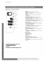
Co_tyo# Remoto de Aco_dic#oy_ado_ de A#re
Las funciones trabajan igual que los controles manuales de su acondicionador de aire.
Pilas:
Retire al tapa en la parte trasera del control remoto e inserte las baterias con los polos (+) y (-) en la direcci6n correcta.
• Use solabente pilas AAA o IEC R03 de 1,5V.
• Retire las pilas si el control remoto no va a set usado durante un
mes o m_s.
• No h_tente recargar las pilas suministradas.
• Todas las pilas deben set reemplazadas a un mismo tiempo.
• No incrinere/as pilas pues pueden explotar.
• No instale las pilas con la polaridad (+/-) inversa.
• Mantenga fuera de/alcance de los ni_os peque_os las pilas y otros artfculos que puedan set tragados.
Pdngase h_mediatamente en contacto con un m_dico si un ni_o peque_o se traga un objeto.
18

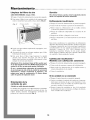
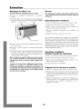
MantenimientOoooooooooooo
Limpieza del filtro de aire
CADA DOS SEMAIVAS:Limpie el filtro.
1. Ponga el Control de alimentaci6n en posici6n apagado.
2. Para retirar el filtro de aire, sujhtelo de las esquinas supe-
riores y remu4valo hacia arriba y hacia afuera (Fig. Z).
_ _ Persianas ajustables Filtros &, aire
@@@@@@@@@@@@@@@@@@@@@@@@@@@@@@@
Servicio
Para ahorrar tiempo y gastos, revise Io siguiente antes de
Ilamar a la empresa de servicio autorizado.
Enfriamiento insuficiente
1" Ponga el Control de alimentaci6n en posici6n apagado.
1" Cierre todas las ventanas y puertas de la habitaci6n.
1" Retire todas las obstrucciones de las rejillas interna
y externa del gabinete de la unidad.
1" Puerta de ventilaci6n (disponible en la mayoria de los
modelos).
1" Inspeccione el filtro y limpielo si estfi sucio.
1" Ponga el termostato y el control maestro en los valores
mils frios.
3. Lfivelo con agua caliente enjabonada, enjufiguelo, sacfi-
dalo y s_quelo.
4. A1 ponerlo de nuevo en su lugar, asegfirese que el lado
frontal quede mirando a usted.
5. Para secar bien el filtro, haga funcionar la unidad
durante unos minutos. Recuerde, que s61o un filtro
limpio harfi funcionar su unidad correctamente y darfi
siempre el servicio mils eficiente.
Advertencia: El no mantener limpio el filtro podria resul-
tar en baja circulacion del aire. NUNCA haga funcionar la
unMad sin el filtro ya que puede quedar inutilizable.
El uso y mantenimiento adecuados del acondicionador
de air prolongara la vMa util de la unMad. Se recomienda
inspeccionar y limpiar anualmente el serpentin y los
pasajes para agua de condensacion. El cliente debera
cubrir los gastos de inspeccion anuaL
Orientaci6n de la
corriente de aire
(Unidad con rejilla directriz ajustable)
La unidad viene equipada con rejillas directrices ajustables
que permiten dirigir la descarga de la corriente de aire. Las
rejillas pueden ajustarse manualmente moviendo las
palancas en la direcci6n deseada (Fig. d).
Bajo ciertas condiciones, los serpentines de enfriamiento
ubicados directamente detrfis del filtro podrian congelarse
y bloquear el pasaje del aire. Esto ocurre por lo general en
acondicionadores de aire cuando la temperatura externa
desciende a menos de 21°C (70°F) mientras que la
humedad se mantiene elevada. Si esto ocurre, simple-
mente apague la unidad y deje que se derrita el hielo antes
de reanudar el funcionamiento normal.
Calefacci6n insuficiente-
Modelos con calefacci6n solamente
1" Ponga el Control de alimentaci6n en posici6n apagado.
1" Cierre todas las ventanas y puertas de la habitaci6n.
1" Retire todas las obstrucciones de las rejillas interna y
externa del gabinete de la unidad.
1" Cierre la ventilaci6n.
Si la unidad no se enciende
1" Ponga el control maestro en posici6n apagado.
1" Vuelva a enchufar el enchufe del cord6n en el tomacor-
riente para cerciorarse de que se estfi haciendo el con-
tacto el_ctrico. (Si no se verifica un contacto firme serfi
necesario cambiar el tomacorriente).
1" Ponga el control de ventilador en alto. Si el ventilador
de circulaci6n de aire no funciona, verifique los disyun-
tores o fusibles de la residencia.
19
La page charge ...
La page charge ...
La page charge ...
La page charge ...
La page charge ...
La page charge ...
La page charge ...
La page charge ...
La page charge ...
La page charge ...
La page charge ...
La page charge ...
-
 1
1
-
 2
2
-
 3
3
-
 4
4
-
 5
5
-
 6
6
-
 7
7
-
 8
8
-
 9
9
-
 10
10
-
 11
11
-
 12
12
-
 13
13
-
 14
14
-
 15
15
-
 16
16
-
 17
17
-
 18
18
-
 19
19
-
 20
20
-
 21
21
-
 22
22
-
 23
23
-
 24
24
-
 25
25
-
 26
26
-
 27
27
-
 28
28
-
 29
29
-
 30
30
-
 31
31
-
 32
32


Maytag 23-11-2231N-004 Manuel utilisateur
- Taper
- Manuel utilisateur
- Ce manuel convient également à
dans d''autres langues
- English: Maytag 23-11-2231N-004 User manual
- español: Maytag 23-11-2231N-004 Manual de usuario
Documents connexes
-
Maytag 23-11-2229N-004 Manuel utilisateur
-
-
-
-
-
-
-
Autres documents
-
 Air Temp B6D30E7A Le manuel du propriétaire
-
 Air Temp b6k32e7a Le manuel du propriétaire
-
Fedders 23-23-0321N-005 s Installation & Operation Manual
-
-
-
-
-
-
-
Kenmore 25370187000 Guide d'installation

