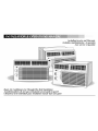
Fedders 23-23-0275N-009 s Installation & Operation Manual
- Catégorie
- Climatiseurs split-system
- Taper
- Installation & Operation Manual

Including Service and Warranty
Incluidos mantenimiento y la garantfa
Avec service et garantie
Room Air Conditioners for Through-The-Wall Installation
Acondicionadores de aire para instalaci6n atravesando la pared
Climatiseur d'air individuel pour installation murale dans une gaine

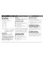
ENGLISH
Electrical Requirements ...... 1
Warning
Notice
Important Grounding Requirements
Installation .......................... 1
Installation
Tools Needed
If You Purchase a New Sleeve
Installation in Existing Wall Sleeve
Operation ............................. 5
Control Fun( tions
C_oling Operation
Heating Operation (Heating Models Only)
Air Cil_ ulation Without di_oling or Heating
Exhaust Operation Without Ci_oling or Heating
Directing Airflow
Cleaning Air Filter
Service ............................... 8
Insufficient Cooling
Insufficient Heating (Heating Models Only)
Unit Fails to Start
Service or Parts Required
Warranty ............................... 9
ESPANOL
Requistos para
la el_ctricos ....................... 10
Aviso
Aviso
Requistos importantes para /a conexidn a tierra
Instalaci6n ......................... 10
Instala(idn
Herramientas necesarias
Si compra una camisa nueva
Instalaci6n en una manga de pared existente
Funcionamiento ................. 14
Fun( iones de control
Operacidn de enfriamiento
Funcionamiento de b calebccidn
(Sobmente en modelos con cale_cci6n )
Cimubci6n fie aire sin enfriamiento o cale_cci6n
Funcionamento del escape sin enfriamiento
o cale_cci6n
Orientacidn del flujo fie aire
Limpieza del filtm de aire
Servicio .............................. 18
Enfriamiento insuficiente
G#efaccidn insuficiente
(Modelos con calebccidn solamente)
Si b unidad no se enciende
Necesidad de servicio o piezas
FRAN_AIS
Exigences _lectrique ......... 20
Avertissement
Avis
Importantes exigences de mise ,_/a terre
Montage ............................. 20
Installation
Outils n6cessaires
Si vous achetez un nouveau manchon
Installation dans un manchon mural existant
Fonctionnement ................. 24
Commandes
Fonctionnement flu c/imatiseur
Fonctionnement du chauf_ge
(Moflbles chauf_nts uniquement)
Cimu/ation d'air sans refroidissement ou chauffage
Fonctionnement de/'¢wacuation d'air
sans refroidissement ou chauf_ge
Direction du flux d'air
Nettoyage du fi/tre ,_air
Service ............................... 28
Refroidissement insuffisant
Chauf_ge insuffisant (Modbles chauf_nts seu/ement)
L'appareil ne se met pas en marche
R_parations ou pi_ces s'avbrent n6cessaires
Garantie ............................. 28
Garantia ............................. 18

Electrical Shock Hazard
1. Plug unit only into grounded ek,ctrkal outleL
2. Do not use an extension cord or plug adaptor wifll
this unit.
3. Do not operate unff wffh front removed.
Failure to follow the above precautions could result in electrical
shock, fire or personalinjury.
ff the air conditioner has a serial plate rating of ] ] 5 vohs
an(] greater than 7.5 anlps it nlust have ffs own filse or cir
cuff breaker, and no other device or unit should be operated
on that filse or circuff breaker.
ff the air conditioner has a serial plate rating of 2°_0vohs
it must have its own filse or circuit breaker, and no other
device or unit should be operated on that fuse or circuff
breaker.
The location of the serial plate that applies to this nlodel
call be Found on the back page of this nlanual.
Notice
Do not operate this air conditioner without proper time
delay circuit protection. Refer to serial plate for proper
power supply requirements.
RECOMMENDED CIRCUIT WIRESIZES
(As installed per building c_;de)
PROTECTORSIZE WIRE GAUGE
15 AMP #1d MINIMUM
20 AMP #12 MINIMUM
_0 AMP #10 MINIMUM
@©©@
l l5V 230V 230V 230V
15A 15A 20A 30A
Product Damage:
Do not cuL aher or renlow! any of the expanded polystyrene
(whffe foam) inside this air conditioner.
For Your Safety:
Do not store or use gasoline or other flanlnlable vapors and
liquids in the vicinffy of this or any other appliance. The
finnes call create a fire hazard or explosion.
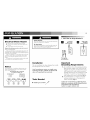
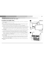
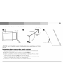
Installation
This air conditioner has been designed for installa-
tion through the wall, in a sleeve.
Note: For performance reasons, we strongly recom-
mend using wall sleeve A7OO5XX. This thru-the-wall
sleeve can be purchased from your dealer.
Tools Needed
• Blade-type screwdriver ,/_
f
1. ELECTRICAL REQUIREMENTS
Grounded
Single outlet
three-prong grounding
wall receptacle wall receptacle
Three-prong
grounding plug
Important
Grounding Requirements
1. Air conditioner has a three-prong grounding
plug on power supply cord, which must be
plugged into properly grounded three-prong
wall receptacle for your protection against
possible shock hazard. For models up to and
including 7.5 amperes use grounding type
wall receptacle to match cord plug (Fig,. 1).
2. For models above 7.5 amperes use single
outlet grounding type wall receptacle to
match cord plug (Fig. 2).
Caution: We recommend that a qualified electrician
install unit in accordance with the National Electrical
Code and local codes and ordinances.
Caution: Use copper conductors only.

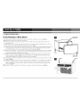
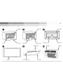
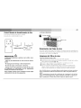
2. SLEEVE INSTALLATION
If You Purchase a New Sleeve
1. Remove front and back cover. Save for future use when air conditioner is removed (Fig. 3).
2. Remove the exterior rear grille from the sleeve.
3. Brush out all debris from inside of sleeve, make sure inside is dean and that the drain holes are
completely clear.
4. Back out screws in exterior grille approximately 1/8". Tip exterior grille while holding on to the wire
loop and pass it through the exterior opening of the sleeve (Fig. 5).
5. The baffle contact area should be at the ]eft. Align grille to engage screw heads through keyhole slots
in the outer flanges of sleeve. Push downward until screws are positioned into bottom of keyhole
slots. Tighten the four (4) screws, unwind and discard the wire loop (Fig. 6).
6. Unpack air conditioner - see instructions on the carton. Depending on the model, your air condition-
er may weigh as much as 95 pounds. To insure safe handling, obtain the necessary help to lift and
position the unit during installation and removal.
7. Slide air conditioner fully into the sleeve, it should be centered in the sleeve so that all seals bear
evenly to prevent air leakage (Fig. 7). NOTE: THE UNIT IS 3" DEEPER THAN THE SLEEVE. THE
UNIT WILL PROTRUDE 3" FROM THE SLEEVE INTO THE ROOM.
8. Assemble trim frame by lying all four pieces face down on a flat surface and snapping them securely
together (Fig. 8).
9. instal[ the insulating foam in the recess of the trim frame, instal[ the 1/4" insulating foam around the
inside circumference of the trim frame. Begin in the bottom ]eft corner and run foam around the
entire circumference of the trim frame. Make sure to keep foam flush with the bottom edge of the
trim frame (Fig. 9).
10. Slide the trim frame onto the unit until the foam makes a sea[ with the wail sleeve (Fig. 10).
D Back coverOutdoor side)
Sleeve
Front cover
(Indoor side)
D Cabinet Sleeve

D Rear grille D New grille D
Label Indoor side Wire Ioo1_ Flange to inside
Baffle contact area
New grille
Drain holes
D D Insulating foam Trim frame
Cabinet
Trim frame 1/4" insulating foam Trim frame

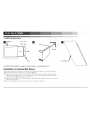
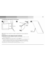
2. SLEEVE INSTALLATION
1/4" to 5/16"
f
Unit FRONT
Level
CAUTION: When installation is complete, the unit must have a rearward slope (Fig. 11).
Metal tab
Deep Filler Panel
Installation in Existing Wall Sleeve
1, Remove all debris from interior of wall sleeve. It may also be necessary to remove existing foam.
2, Break out metal tabs if the sleeve is so equipped (Fig. 12).
3, Measure the wall sleeve depth. If the sleeve is more than 18" deep, remove the condenser baffle
making sure to retain the two screws. Using the two screws from the condenser baffle, attach the
Deep Filler Panel (Fig. 13) in place of the baffle.
4, Slide the unit into the sleeve until the condenser baffle (Deep Filler Panel if installed) makes contact
with the exterior grille.
5. See items 8 through l l of preceeding instructions to complete installation.

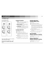
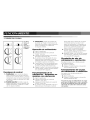
3. CONTROL PANEL
One of the pictured control
panels is similar to your panel.
F_
HIc_o_
• , ee
LO
Caution: If air conditioner is shut off, wait a minimum
of three minutes before restarting.
The heat from this unit is designed only as a supple-
mental heat source in addition to regular heating
systems.
Control Functions
1. Vent: Circulates fresh air and helps remove
sta]e air when in the open position.
Maximum air circu]ation and cooling occur
when in the dosed position.
2, Master Control: Turns unit on and off.
Selects desired function of unit, cooling, fan,
or heating (on some models).
3, Thermostat: Controls the unit thermostat,
which regulates room temperature by auto-
matica]]y turning compressor or heating ele-
ment (on some models) on and off.
Cooling Operation
1, Close Vent.
2, Turn Thermostat to "Cooler".
3, Turn Master Control to HI COOL.
4, If room becomes too coo] for comfort, turn
the Thermostat counterclockwise until the
compressor turns off (the fan will remain in
operation).
5, When the desired comfort ]eve] is reached,
the Master Control may be turned to the LO
COOL setting.
6, To turn the unit off, or in event of a power
interruption, turn the Master Control to OFF.
Heating Operation -
Heating Models Only
1, Close Vent.
2, Turn Thermostat to "Warmer".
3, Turn Master Control to H] HEAT.
4, If room becomes too warm for comfort, turn
the Thermostat clockwise until the heating
elements turn off (air circu]ating fan will
remain in operation). The temperature will
be automatica]]y maintained. Further adjust-
ment of Thermostat may be needed to reach
desired comfort level.
5, When the desired comfort ]eve] is
reached, the Master Control may be turned
to LO HEAT.
6, To turn unit off, or in event of power inter-
ruption, turn Master Control to OFF.
Air Circulation
Without Cooling or Heating
To circulate and fiher the ,_i_; proceed as follows:
1, Close Vent.
2, Turn Master Control to HI FAN.
Exhaust Operation
Without Cooling or Heating
To exhaust stale ai_; proceed as follows:
1, Open Vent.
2, Turn Master Control to HI FAN.

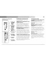
4. ELECTRONIC CONTROL PANEL
•i o-- ....
• _M__0 ........
o°,_
0
CI
@
Heat
One of the pictured control
Cool Only
A. Set
--- A Temperature
/Timer
.... B Display
.... C
B. Temperature
D /Timer Hour
Controls
E
F C. Check Filter
Light/Reset
G
D. Timer
A Control
B
E. Fan Speed
C Control
D
E F. Mode
Control
F
G G. Power
Control
_anels is similar to your panel.
Power Control
The Power Control turns the unit on and off.
Set Temperature/
Timer Display
Shows the set temperature when the unit is in
operation and hours when the timer is being set.
THE TEMPERATURE DISPLAY ONLY SHOWS THE
SET TEMPERATURE, NOT THE ACTUAL ROOM
TEMPERATURE.
Temperature/
Timer Hour Controls
These buttons are used to raise or lower the set
temperature in increments of 1o from 66°F to 88°F.
By depressing both buttons at once, the display
will toggle between Celsius and Fahrenheit. When
the timer is being set, these buttons are used to
change the hour setting in increments of 1 from
00 to 24.
Check Filter Light/Reset
After 250 hours of usage the Check Filter light
will turn on. At this time, the filter needs to be
removed and cleaned (see page 9). After the filter
is cleaned and repositioned, depress the Reset
button. This will restart the counter and turn the
light off.
Mode Control
A green light will indicate which mode is current-
ly being utilized.
Cool Mode - The unit will circulate and coo]
the air.
Heat Mode (Heat Models Only)- The unit
will circulate and heat the air.
Heater Safety Feature- When heater is powered
off, low fan will automatically stay on and run
for 60 seconds to ensure the removal of residual
heat, meanwhile, the Low Fan LED blinks until
the low fan stops.
Fan Mode - The unit will only circulate the air.
Energy Saver Mode -
(The energy saver mode is designed to operate
with Cool mode only)
The fan will switch from the set fan speed to LO
whenever the compressor turns off in response to
the thermostat. When the compressor cycles
back on, the unit will return to the original fan
setting.
Fan Speed Control
High, Medium*, Low and Auto
The settings are adjusted with the Fan Speed
Control, each time the button is depressed it
changes the setting. A green light will indicate
which setting is currently being used.
When the AUTO feature is selected while the air
conditioner is in the COOL or HEAT mode, the
fan speeds will change automatically as the tem-
perature in the room changes.
COOL Mode
• 7 ° or more above the set temperature
will use HI FAN.
• 4 ° or less above the set temperature
will use LO FAN.

7
HEAT Mode
• 9 ° or more below the set temperature
will use HI FAN.
• 4 ° or less below the set temperature
will use LO FAN.
*MEDIUM FAN NOT available on HEAT models.
Timer Control
The timer can be set to either turn the unit on or off.
To turn the unit on using the Timer:
Depress the timer key when the power is off, the
display will read 00 Adjust to the desired number
of hours before TURN ON using the up/down
arrows
• The display will show the time by hours left until
TURN ON.
• To Turn the timer off, depress the timer key.
• A green light next to the Timer Control indicates
that the timer is set.
To turn the unit OFF using the Timer:
Depress the timer key when the power is on, the
display will read 00 Adjust to the desired number
of hours before TURN OFF using the up/down
arrows The display will automatica]]y go back to
the set temperature after 10 seconds
• To display the amount of time left until TURN
OFF depress the timer button once
• To turn the TIMER OFF depress the timer button
twice
• A green light next to the Timer Control indicates
that the timer is set
Built-in three minute timing delay.
This electronic controlled unit will not automatically
resume operation after a power failure.
If this electronic unit will not respond to touch pad
or remote control commands, it is necessary to
unplug the unit from the electrical outlet for five sec-
onds and then plug the unit back in.
Caution:
Do not block air circulation to outside louvers
of cabinet.
Do not block air flow inside with blinds, cur-
tains, or furniture, or outside with shrubs,
enclosures, or other buildings.
Do not run air conditioner with outside protec-
tive cover in place. This could result in mechan-
ical damage withh_ the air conditioner.
4. FRONT PANEL
[] Adjustable louvers
filter
Directing Airflow
Unit is engineered with adjustable louvers to
direct discharge airflow. Louvers are manua]]y
adjusted by moving levers in direction of desired
airflow (fig. le).
Cleaning Air Filter
MECHANICAL CONTROL PANEL:
every two weeks
1. Turn Master Control to OFF.
2.
3.
4.
5.
Clean the filter
Remove the air filter by grasping the top cor
ners and pu]]ing it up and out of the unit
(Fig. 10),
Wash in hot soapy water, rinse and shake dry.
Replace the fi]ter, with the front of the fi]ter
toward you.
To dry the fi]ter thoroughly, run your unit for
a few minutes. Remember, only a clean fi]ter
works properly and de]ivers top efficiency at
every setting.
ELECTRONIC CONTROL PANEL:
1. After 250 hours of usage the Check Filter
light will turn on
2. Remove the air fi]ter by grasping the top cor
ners and pu]]ing it up and out of the unit
(Fig. 10).
3. Wash in hot soapy water, rinse and shake dry.
4. Replace the fi]ter, with the front of the fi]ter
toward you.
5. After the fi]ter is cleaned and repositioned,
depress the Reset button. This will restart the
counter and turn the light off.
Note: Failure to keep air filter clean will result in poor
air circulation. DO NOT operate without filter. This
can render the unit inoperative.
Proper use and care of your air conditioner will help
ensure longer life of the unit. It is recommended to
annually inspect and clean the coils and condensate
water passages. Expense of annual inspection is the
consumers' responsibility.

Air Conditioner
Remote Control
The functions work the same as your
air conditioner's touch controls.
BatteryInstallation_ ]'_
CAUTION
Batteries may become hot, leak, or explode due
to improper use.
• Do not install the batteries with the polarity (+/-)
reversed.
• Do not subject batteries to fire or high temperatures.
• Do not attempt to recharge, short, or disassemble.
• Tape over lithium battery contacts before disposal.
Follow local codes for battery disposal.
Keep batteries and other things that could be swal-
lowed away from young children. Contact a doctor
immediately if an object is swallowed.
Service
Tosave time and expense, check the following before
calling an authorized service station.
Insufficient Cooling
• Turn Master Control to OFF.
• Shut all windows and doors in room.
• Remove any obstructions from inside and
outside cabinet louvers.
• Close Air Exchanger,
• Inspect filter and clean if dirty,
• Turn Thermostat to Cooler and Master
Control to HI COOL,
Under certain conditions the cooling coils directly
behind the filter, may ice up and block the airflow.
This is a common occurrence in air conditioners
caused when the outside temperature drops below
70°F (21°C) while the humidity remains high. If
this happens, simply turn the unit off and allow
the ice to melt, then resume normal operation.
Insufficient Heating-
Heating Models Only
• Turn Master Control to OFF.
• Shut all windows and doors in room.
• Remove any obstructions from inside and
outside cabinet louvers.
• Close Vent.
• Turn Thermostat to Warmer and Master
Control to HI HEAT.
Unit Fails to Start
• Turn Master Control to OFF.
• Rep]ug line cord plug into outlet to be sure
e]ectrica] contact is being made. (if firm con-
tact is not being made, outlet may have to be
replaced).
• Turn Master Control to FAN. If air circu]ating
fan does not operate, check house circuit
breaker (or fuses).
For Models Installed in
North America - If Service
or Parts are Required
First, make the recommended checks. If it appears
that service or parts are still required, see your
room air conditioner warranty "How to Obtain
Warranty Service or Parts".
For Models Installed
Outside North America
For room air conditioners purchased for use out-
side North America, the manufacturer does not
extend any warranty either expressed or implied.
Consult your local dealer for any warranty terms
extended by the importer in your country.

9
Room Air
Conditioner Warranty
(Within the 48 contiguous United States, state of Hawaii,
the District of Columbia, Puerto Rico and G_nada)
Full (One Year) Parts and Labor Warranty
During the first year after the date of original pur-
chase, Fodders Appliances will, through its autho-
rized servicers and free of charge to the owner or
any subsequent user, repair or replace any parts
which are defective in material or workmanship
due to normal use. Ready access to the air condi-
tioner for service is the responsibility of the owner.
Limited (Five Year) Sealed System/
(Two Year) Fan Motor Parts Warranty
In addition to tile full (one year) parts and labor
warranty described above, Fodders Appliances
will, through its authorized servicers or parts dis-
tributors, exchange sealed system parts (consisting
of compressor, evaporator, condenser, and inter-
connecting tubing) during the second year through
fifth year, and the fan motor during the second
year, both from the original date of purchase, pro-
viding the parts are defective in material or work-
manship. Transportation, handling, or labor costs
to diagnose, repair, or replace such defective parts
are not covered by this limited parts warrantyand
are the owner's responsibility.
Note: In the event of any required parts replacement within the
period of this wam_nty, Fedde_s Appliances replacement parts
shall be used and will be wam_nted only for the period remain-
ing on the original wam_nty.
Exceptions
The above warranty does not cover failure to
function caused by damage to the unit while in
your possession (other than damage caused by
defect or malfunction), or by its improper installa-
tion, or by unreasonable use of the unit, including
without limitation, failure to provide reasonable
and necessary maintenance or to follow the writ-
ten Installation and Operating Instructions. If the
unit is put to commercial, business, rental, or
other use or application other than for consumer
use, we make no warranties, express or implied,
including, but not limited to, any implied warranty
of merchantability or fitness for particular use or
purpose.
THE REMEDIES PROVIDED FOR IN THE ABOVE
EXPRESS WARRANTY ARE THE SOLE AND EXCLUSIVE
REMEDIES THEREFOR, NO OTHER EXPRESS WAR-
RANTIES ARE MADE. ALL IMPLIED WARRANTIES,
IN(ZUDING BUT NOT LIMITED TO ANY IMPLIED
WARRANTY OF MERCHANTABILITY OR FITNESS FOR
A PARTICULAR USE OR PURPOSE, ARE LIMITED IN
DURATION TO ONE YEAR FROM THE DATE OF ORIGI-
NAL PURCHASE. IN NO EVENT .SHALL FEDDERS APPLI-
ANUES BE LIABLE FOR INDIRECT, INCIDENTAL, OR
CONSE(_UENTIAL DAMAGES, EVEN IF ADVISED IN
ADVANUE OF THE POSSIBILITY OF SUCH DAMAGES.
NO WARRANTIES, EXPRESS OR IMPLIED, ARE MADE
TO ANY BUYER UPON RESALE.
Some states do not allow ]imitations on how long
an imp]led warranty lasts or do not a]]ow the
exclusion or ]imitation of incidental or consequen-
tia] damages, so the above ]imitations or exclu-
sions may not app]y to you. This warranty gives
you specific legal rights, and you may also have
other rights which may vary from state to state.
No warranties are made for units sold outside of the
above stated areas. Your distributor or final seller may
provide a warranty on units sold outside of these areas.
How to Obtain Warranty Service or Parts
Service for your room air conditioner will be provided
by CareCo, a division of the manufacturer with autho-
rized independent servicers nationwide.
Note: Before calling for service, carefully read the Installation and
Operating Instructions booklet. Then if you need service:
1. Call a CareCo authorized servicer and advise
them of mode] number, serial number, date
of purchase and nature of complaint. Service
will be provided during normal working
hours. Contact your dealer for the name of
an authorized servicer, if unknown to you.
2, If your dealer is unable to give you the name
of a servicer or if you need other assistance,
call the following toll-free number for the
name of an authorized servicer or authorized
parts distributor:
1-800-332-6658
or you may write:
CareCo, Service Department
415 14/.Wabash Ave., P.O. Box 200
Effingham, IL 62401
Proof of Purchase Date
It is the responsibility of the consumer to estab]ish the
origina] purchase date for warranty purposes. We recom-
mend that a bill of sa]e, cancelled check, or some other
appropriate payment record be kept for that purpose.

Peligro de
descarga el6ctrica
1. Enchufe la unidad en un toulacorriente con conexi6n
_ tiem_.
2. No use un cable de extensi6n ni un adaptador de
enchufe con este apar_lto.
3. No Io h_ga funcionar sin I_ cubierta ddamera.
El no seguir las precauciones enumeradas anteriormente podrfa
causar descargas el_ctricas, incendio o lesiones personales.
Si el acondicionador de aire trae en la placa una dasifi
caci6n de H5 voltios y m4s de 7.5 _mperios, entonces
debe ir conectado a su propio fiMble o cortacircuffos y
ning(m otto _parato o unidad se podr4 conedar a dicho
Fusible o cortacircuitos.
Si el acondidonador de aire tr_e en la plata una ch_sifi
cad6n de 230 voltios, emonces deber4 ir conectado a su
propio fusible o cortacircuffos y ningdn otto _parato o
unidad se podr4 conectar _ dicho fiMble o cortacircuffos.
I a ubicaci6n de la plata en d,ste nlodelo se encuentra
indicada en la dltinla p4gin_ de 6ste nlanual.
Aviso
No haga funcionar estre aire acondicionado sin un circuffo
tenlporizador que brinde la protecci6n ade_uada. En la
plata de idenfificaci6n aparecen los requisitos correctos de
alinlentaciOn.
TAMA[qOS RECOMENDADOS
PARA LOSALAMBRES DEL CIRCUITO
(Insta/ado seg_nlosreg/amentos de construcci6n)
TAMA[_O DEL PROTECTOR CALIBRE DEL ALAMBRE
15 AMP #14 MINIM()
20 AMP #12 MINIMO
30 AMP #10 MINIMO
@©©@
l15V 230V 230V 230V
15A 15A 20A 30A
Dafio al producto:
No code, a[tere ni retire el poliestireno expandido (espunla
bJanca) (]tie est4 dentro de[ acondicionador de aire.
Para Su Seguridad
No guarde ni ufilice gasolina ni otros [[quidos o vapores
inflamables en las inmediaciones de este o ning(m otto
aparato. [as enlanaciones pueden crear tin peJi,,grode
incendio o explosi6n.
Instalaci6n
Este acondicionador de aire ha sido disefiado
para instalaci6n atravesando ]a pared, dentro de
una manguito.
Nora: Por motivos de rendimiento, recomendamos
firmemente usar la manga para pared A7OO5XX. Puede
comprar esta manga empotrable a su proveedor.
Herramientas necesarias
• Destornillador com6n /_
<//"
__iiiiiiii!iii!i!!!!!!!!!!!!!!!iiii!i!!iiii!iii!!!!!!!!!!!!!ii;i
1. REQUISTOS PARA LA ELECTRICOS
Recept&culo mural
de tres espigas con
puesta a tierra.
_chuf_sta a tlerra
con tres esp=gas
D Recept&culomural con salida
simple de puesta
erra
Requistos importantes
para la conexi6n a tierra
1. El equipo de aire acondicionado tiene en el
cord6n de corriente un enchufe a tierra de
tres puntas, el cua] debe ser introducido en
un tomacorriente de tres puntas debidamente
conectado a tierra para protecci6n contra
posibles descargas el6ctricos. Para modelos
de hasta 7.5 amperios utilice un tipo de
tomacorriente con conexi6n a tierra, adecua-
do para el enchufe del equipo (Fig,. 1).
2. Para modelos de m_is de 7.5 amperios, util-
ice un tomacorriente con conexi6n a tierra
para un solo enchufe (Fig. 2).
Precauci6n: Recomendamos que un electricista callfica-
do instale la unidad de acuerdo alas normas el6cticas
nacionales y las nonnas y regulaciones locales.
Precauci6n: Utilice solamente conductores de cobre.

2. INSTALACION DEL MANGUITO Y DEL CHASIS
Si compra una manga nueva
1. Retire ]as cubiertas delantera y trasera, Gu_irdelas para uso futuro cuando retire el acondicionador
de aire (fig. 3).
2, Retire ]a rejilla exterior trasera de ]a manga,
3. Use un cepi]]o para eliminar toda ]a suciedad de dentro de ]a manga; aseg0rese de que el interior
est6 ]impio y que los orificios de drenaje est6n comp]etamente ]ibres,
4. Afloje los torni]]os de ]a reji]]a exterior aproximadamente 1/8", Incline ]a reji]]a exterior mientras
sostiene el buc]e de cable y p_iselo a trav6s de ]a abertura exterior de ]a manga (Fig,. 5).
5. El _irea de contacto deflectora debe estar a la izquierda, Alinee la rejilla para que ]as cabezas de los
torni]]os pasen por ]as ranuras con forma de bocal]ave que se encuentran en ]as pestafias externas de
]a manga, Empuje hacia abajo hasta que los torni]]os est6n posicionados en ]a parte inferior de ]as
ranuras con forma de bocal]ave, Ajuste los cuatro (4) torni]]os; desenrosque y deseche el buc]e de
cable (Fig. 6).
6, Desempaque el acondicionador de aire - Vea ]as instrucciones en ]a caja, Dependiendo del modelo,
su acondicionador de aire puede pesar hasta 95 ]ibras, Para que el manejo sea seguro, obtenga ]a
ayuda necesaria para ]evantar y posicionar ]a unidad durante ]a instalaci6n y el desmontaje.
7. Des]ice e] acondicionador de aire comp]etamente dentro de ]a manga. Debe centrarse dentro de ]a
manga de manera tal que todos los sellos soporten ]o mismo para evitar p6rdidas de aire (fig. 7).
NOTA: LA UNIDAD ES 3" M/_S PROFUNDA QUE LA MANGA. LA UNIDAD SOBRESALDRA 3" DE
LA MANGA DENTRO DE LA HABITACI(')N.
8, Arme el bastidor colocando las cuatro piezas boca abajo sobre una superficie p]ana y uni6ndolas a
presi6n (Fig. 8).
9, Instale la espuma aisladora en el hueco de[ bastidor. Instale la espuma aisladora de 1/4" airededor
de la circunferencia interior de] bastidor. Comience en la esquina inferior derecha y recubra con
espuma toda la circunferencia de] bastidor. Aseg0rese de que la espuma est6 emparejada con el
borde inferior de] bastidor (Fig. 9).
10, Deslice e] bastidor sobre la unidad hasta que la espuma forme un se]lo con la manga de la pared
(Fig. 10).
D Cubierta traseraLado externo)
Manguito
Cubierta delantera
(Lado interior)
D Gabinete Manga

[I _ejilla trasera D Rejilla nueva D
Etiqueta
interior
Gaza de alambre Reborde hacia adentro
Area de contacto del tabique Agujeros de drenaje
D D Espuma aislante _ Bastidor
Gabinete
Bastidor Espuma aislante de 1/4" Bastidor

z
2. INSTALACION DEL MANGUITO Y DEL CHASIS
anga de la pared
1/4" a 5/16"
-E
Unldad FRONTAL
Nivel
Leng_eta
de metal
PRECAUCI_)N: Cuando la instalaci6n est_ completa, la unidad debe estar levemente inclinada hacia
atr_s (Fig. 11).
Panel de
relleno profundo
Instalaci6n en una manga de pared existente
1, Retire todos los desechos de] interior de ]a manga de ]a pared. Es posible que tambi_n sea necesario
retirar ]a espuma existente.
2, Rompa ]as ]engOetas de meta] si est_in presentes en ]a manga (fig. 12).
3, Mida ]a profundidad de ]a manga de ]a pared. Si ]a manga tiene m_is de 18" de profundidad, retire e]
deflector de] condensador asegur_indose de retener los dos torni]]os. Usando los dos torni]]os de]
deflector de] condensador, co]oque el panel de relleno profundo (fig. 13) en ]ugar del deflector.
4, Des]ice ]a unidad dentro de ]a manga hasta que el deflector de] condensador (el panel de rel]eno
profundo si est,1 insta]ado) haga contacto con ]a reji]]a exterior.
5, Siga los pasos 8 a 11 de las instrucciones anteriores para completar la instalacidn.

3. TABLERO DE CONTROL
OFF
C
Uno de los
tableros de
control
ilustradoses
similar al de
su unidad.
Funciones de control
1. Ventilaci6n: Hace circular aire fresco y
ayuda a eliminar el aire viciado cuando se
encuentra en ]a posici6n abierta. La m_ixima
circu]aci6n de aire y e] m_iximo enfriamiento
se producen cuando se encuentra en ]a posi-
ci6n cerrada.
2, Control maestro: Enciende y apaga ]a
unidad. Selecciona ]a funci6n deseada de ]a
unidad: enfriamiento, venti]aci6n o calefac-
ci6n (en algunos modelos).
3, Termostato: Contro]a el termostato de
]a unidad, que regula ]a temperatura de ]a
habitaci6n a] encender y apagar autom_itica-
mente e] compresor o ]a calefacci6n
(en aigunos modelos).
Operaci6n de enfriamiento
1, Cierre ]a ventilaci6n.
2, Co]oque el termostato en ]a posici6n
"Cooler" (m4s fr[o).
3, Co]oque el control maestro en ]a posici6n
HI COOL (Enfriamiento alto).
4, Si comienza a hacer demasiado fifo en ]a
habitaci6n, gire el termostato en sentido
antihorario hasta que el compresor se apague
(el venti]ador seguir4 en movimiento).
5, Cuando ]ogre el nive] de comodidad desea-
do, puede co]ocar el Control Maestro en ]a
posici6n LO COOL (Enfriamiento bajo).
6, Apague ]a unidad, o en caso de una interrup-
ci6n de energfa, co]oque el Control Maestro
en ]a posici6n OFF (apagado).
Funcionamiento de la
calefacci6n - Solamente en
modelos con calefacci6n
1, Cierre ]a ventilaci6n.
2, Co]oque el termostato en ]a posici6n
"Warmer" (m_is ca]or).
3, Co]oque el Control Maestro en ]a posici6n
HI HEAT (Ca]or alto).
4, Si comienza a hacer demasiado ca]or en ]a
habitaci6n, gire el termostato en sentido
5,
6,
horario hasta que ]a calefacci6n se apague
(el ventilador que hace circular el aire
seguir_i en movimiento). La temperatura se
mantendr_i autom_iticamente. Quiz_i deban
hacerse m_is ajustes de] termostato para
]ograr el hive] de comodidad deseado.
Cuando ]ogre el nivel de comodidad
deseado, puede co]ocar el Control Maestro
en ]a posici6n LO HEAT(Ca]or bajo).
Apague ]a unidad, o en caso de una interrup-
ci6n de energia, co]oque el Control Maestro
en ]a posici6n OFF (apagado).
Circulaci6n de aire sin
enfriamiento o calefacci6n
Para hater circular el aire y fihrarla, proceda
de la siguiente manera:
1, Cierre ]a ventilaci6n,
2, Coloque el control maestro en la posici6n
HI FAN (Ventilaci6n alta),
Funcionamiento del escape
sin enfriamiento o calefacci6n
Para quitar el aire viciado, proceda de la
siguiente rfr,_llel?_:
1, Abra la ventilaci6n,
2, Coloque el control maestro en la posici6n
HI FAN (Ventilaci6n aita),
Precauci6n: Si apaga el acondicionador de abe, espere
pot Iomenos tres minutos antesde volver a encenderlo.
Elcalor de estaunidad debe usarses61ocomo fuente
adicional de calor adem_sde lossistemasde calefac-
ci6n normales.

4. PANEL DE CONTROL ELECTRONICO
15
o j....
Cool Only
A. Pantalla de
.... A configu-
raciOn de
..... B temperature/
reloj
.... C
B. Controles de
D temperatura/
horas de reloj
E
C. Luz de verifi-
F caciOn de
flltro/
Reinicializar
G
D. Control de
reloj
E. Control de
velocidad de
ventilador
F. Control de
modo
G. Control de
alimentaciOn
El panel de control de la ilustraciOn es similar al suyo.
Control de alimentaciOn
El control de alimentaciOn enciende y apaga la
unidad,
Pantalla de configuraciOn de
temperatura/reloj
Muestra ]a temperatura fijada cuando ]a unidad
eski en funcionamiento y ]as horas en que se fija
el reloj. LA PANTALLA DE TEMPERATURA Sd,)LO
MUESTRA LA TEMPERATURA FIJADA, NO LA
TEMPERATURA REAL DE LA HABITACIC)N.
Controles de
temperatura/hora del reloj
Estos botones se usan para aumentar o reducir ]a
temperatura en incrementos de I grado desde 66
hasta 88 grados. Si se presionan los dos botones a]
mismo tiempo ]a pantalla cambiar_i entre Celsius y
Fahrenheit. Cuando se fija el reloj, estos botones
se usan para cambiar ]a hora en incrementos de 1
desde 00 a 24.
Luz de verificaciOn de
filtro/reinicializar
DespuOs de 250 horas de uso se encender4 ]a ]uz
de verificaci6n de filtro. Cuando esto sucede,
debe quitarse y ]impiarse el filtro (ver p4gina 18).
DespuOs de ]impiar y volver a co]ocar el filtro,
presione el bot6n Reset (Reinicializar). Este bot6n
volver4 a cero el contador y apagar4 ]a ]uz.
Control de modo
El control de modo tiene tres posi-
ciones: FAN (ventilaci6n), COOL (enfriamiento),
y ENERCY SAVER (ahorro de energ[a). Una
]uz verde indicar_i qu6 modo se eski usando
actualmente.
Modo de enfriamiento - La unidad hat4
circular el aire y 1oenfriar4.
Modo de CalefacciOn (Solamente en
modelos con calefacciOn) - La unidad har_
circular el aire y 1ocalefacciOn,
Caracter]sticas de Seguridad del Calentador -
Cuando se apaga el calentador, el venti]ador per-
manece autom.ticamente encendido en un ajuste
de velocidad bajo y funciona durante 60 segundos
para e]iminar todo el ca]or residual, La ]uz LED
del venti]ador destel]a hasta que el venti]ador se
detiene,
Modo de ventilaciOn - La unidad s0lo har_i
circular el aire.
Modo de ahorro de energia - El ventilador
pasar_i de ]a posiciOn fijada a LO cada vez que
el compresor se apague en respuesta a] termosta-
to. Cuando el compresor se vuelve a encender,
]a unidad volver_i a ]a posiciOn de ventilador
original.

Control de velocidad
del venti|ador
El control de ve|ocidad deJ veatiJador |Jeae cuatm posiciones:
High (alto), Medium (medio), Low (bajo), y Auto (autom_itico). Estas posiciones
se ajustan con el control de ve]ocidad de] venti]ador; cada vez que se presiona
el bot6n se cambia de posici6n. Una luz verde indicar_i la posici6n usada
actualmente.
Cuando se se]ecciona Auto mientras el acondicionador de aire se encuentra en
el modo COOL, ]as ve]ocidades de] venti]ador cambiar_in autom_iticamente si
cambia ]a temperatura de ]a habitaci6n.
Modo de enlrJamiento -
• 7 grados o m_s sobre la temperatura fijada, usar_ HI FAN.
• 4 - 7 grados por encima de la temperatura fijada, usar_ MED FAN.
• 4 grados o menos por encima de la temperatura fijada, usar_ LO FAN.
Medo de Calefacci6n -
• 7 grados o m_s menos de la temperatura fijada, usar_ HI FAN.
• 4 grados o menos debajo de la temperatura fijada, usar_ tO FAN.
Control de| reloj
El temporizador puede hacer que la unidad se prenda o apague.
Para PRENDER [a unidad usando el temporJzado_
e Presione ]a tecla de] temporizador cuando el suministro de energfa est6 apa-
gado, ]a panta]]a leer_i 00. Ajuste a] n_mero deseado de horas antes que SE
PRENDA usando ]as flechas de arriba /abajo.
La panta]]a mostrar_i el tiempo por horas que fa]tan para que SE PRENDA.
Para apagar el temporizador, presione ]a tec]a
de] temporizador.
Una luz verde junto a] control de] temporizador indica que se ha prendido.
Para APAGAR |a unidad usando el temporizador.
Presione ]a tecla de] temporizador cuando el suministro de energ[a
est6 prendido, ]a panta]]a ]eer_i 00. Ajuste a] nOmero de horas
deseadas antes de APAGAR usando ]as flechas de arriba / abajo. La
panta]]a ir_i autom_iticamente a la temperatura programada despu6s
de 10 segundos.
Para mostrar ]a cantidad de tiempo hasta que SE APAGUE, presione
el bot6n de] temporizador una vez.
Para APAGAR el temporizador, presione el bot6n dos veces.
Una ]uz verde junto a] control de] temporizador indica que se ha
prendido.
Mecanismo de retraso de tres minutos incorporado
Este aparato controlado electr6nicamente reanudar_ su operaci6n
despu_s de la interrupci6n del servicio el_ctrico.
$i este aparato electr6nico no responde a los mandos del control
remoto o cojinete t_ctil, ser_ necesario desenchufarlo cinco segundos
y luego volver a enchufar.
Precaucion;
Si apaga el acondicionador de aire, espere pot [o menos tres minutos
antes de volver a encenderlo.
No obstruya el flujo de aire en el interir con persianas, cortinas o
muebles; o en el exterior con arbustos, cercas u otras construc-
ciones.
No haga funcionar el aparato de aire acondicionado con el protec-
tor exterior instalado, ya que esto podrfa ocasionar da_os mec_ni-
cos dentro de la unidad.

Contro/ Remoto de Acondicionador de Aire
Las funciones trabajan igua] que los controles
manua]es de su acondicionador de aire,
® @
© ©
Instalaciondelabater|a_ _'j
PRECAUCION
La pila puede calentarse o explotar si se la utiliza incor-
rectamente.
• Utilice la pila determinada en este manual de instruc-
clones.
• No exponga la pila al fuego o altas temperaturas.
• No trate de cargar, cortocircuitar o desarmar.
• Coloque cinta en los contactos de la pila de litio antes
de deshacerse de ella.Cumpla con los reglamentos
locales para deshacerse de las pilas.
Tenga cuidado; pueden ocurrir accidentes cuando utilice
este producto cerca de ni_os pequen_os.
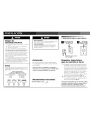
4. PANEL FRONTAL
Persianas ajustables
Filtro de aire
Orientaci6n del flujo de aire
En ]a parte superior de] frente de ]a unidad se encuentran persianas ajustables para
orientar ]a descarga de] flujo de aire. AjOstelas para orientar el aire de acuerdo con
los requisitos de ]a habitaci6n (Fig. 14).
Limpieza del filtro de aire
CADA DOS SEMANAS: Limpie el filtro
1. Coloque el Control Maestro en ]a posici6n OFF (apagado).
2. Retire e] fi]tro de aire tomando ]as esquinas superiores y tirando hacia arriba y
hacia afuera de ]a unidad (Fig. 14).
;3. L_ive]o en agua jabonosa tibia, enju_igue]o y sactida]o para secar]o.
4. Vuelva a co]ocar el fi]tro, con e] frente hacia usted.
5. Para secar e] fi]tro comp]etamente, ponga en marcha ]a unidad durante
a]gunos minutos. Recuerde: La unidad s6]o funcionar_i adecuadamente y
tendRi un a]to rendimiento en cua]quier posici6n si e] fi]tro est,1 ]impio.
Nora: Si el filtro de aire no se mantiene limpio no podr_ obtenerse una buena circulaci6n
del aire. NO PONGA la unidad en funcionamiento sin el filtro. Esto podrfa inutilizar la
unidad.
El uso y mantenimiento adecuados del acondicionador de air prolongar_ la vida (itil de la
unidad. Se recomienda inspeccionar y limpiar anuahnente el serpentfn y los pasajes para
agua de condensaci6n. El cliente deber_ cubrir los gastos de inspecci6n anual.

Servicio
Para ahorrar tiempo y gastos, revise Io siguiente antes
de Ilamar a la empresa de servicio autorizado.
Enfriamiento insuficiente
• Ponga el control maestro en posici6n
apagado "OFF".
• Cierre todas ]as ventanas y puertas de ]a
habitaci6n.
• Retire todas ]as obstrucciones de ]as reji]]as
interna y externa del gabinete de ]a unidad.
• Ponga el intercambiador de aire en ]a posi-
ci6n de cerrado.
• ]nspeccione e] fiitro y ]fmpie]o si est,1 sucio.
• Ponga e] termostato en posici6n "10".
• Co]oque el termostato en ]a posici6n Cooler
(m_is fifo) y el Control Maestro en ]a posici6n
HI COOL (Enfriamiento alto).
Bajo ciertas condiciones, los serpentines de enfri-
amiento ubicados directamente detr._is del filtro
podffan congelarse y bloquear el pasaje de] aire.
Esto ocurre por Io general en acondicionadores
de aire cuando la temperatura externa desciende
a menos de 21 °C (70°F) mientras que la humedad
se mantiene elevada. Si esto ocurre, simplemente
apague la unidad y deje que se derrita el hie]o
antes de reanudar el funcionamiento normal.
Calefacci6n insuficiente-
Modelos con
calefacci6n solamente
• Ponga el control maestro en posici6n
apagado "OFF".
• Cierre todas las ventanas y puertas de
]a habitaci6n.
• Retire todas ]as obstrucciones de ]as reji]]as
interna y externa de] gabinete de la unidad.
• Cierre ]a ventilaci6n.
• Co]oque el termostato en ]a posici6n Warmer
(m4s calor) y el Control Maestro en ]a posi-
ci6n HI HEAT (Calor alto).
Si la unidad no se enciende
Ponga el control maestro en posici6n
apagado "OFF".
• Vue]va a enchufar el enchufe de] cord6n
en el tomacorriente para cerciorarse de que
se est,1 haciendo el contacto el6ctrico. (Si no
se verifica un contacto firme ser_i necesario
cambiar el tomacorriente).
• Ponga el control maestro en venti]ador a]to
"FAN". Si el venti]ador de circu]aci6n de
aire no funciona, verifique los disyuntores o
fusibles de ]a residencia.
Para modelos instalados
en Norteam6rica -
En caso de necesidad de
servicio o piezas
Haga primero ]as verificaciones recomendadas. En
caso de necesitarse servicio o piezas, consu]te en
]a garanfia de su acondicionador de aire en ]a sec-
ci6n "C6mo obtener servicio o piezas de garanfia".
Para modelos instalados
fuera de Norteam6rica
En el caso de los acondicionadores de aire
adquiridos para uso fuera de Norteam6rica, e] fab-
ricante no otorgar,_i ninguna garantfa imp]fcita ni
explfcita. Consulte a su distribuidor autorizado
local sobre ]as condiciones de ]a garant[a extendi-
da por el importador de los equipos en su pa[s.
Garantia del
acondicionador de aire
(Dentro de los 48 estados contiguos de los Estados
Unidos, estado de Hawai, Distrito de (blumbia,
Puerto Rico y G_nad_)
Garantfa completa (un afro) de piezas y mano de obra
Durante el primer afro a partir de ]a fecha de com-
pra original, Fedders Appliances reparar._i o susti-
tuir_i, a trav6s de talieres de servicio autorizados y
sin costo para el primer comprador ni para los
propietarios posteriores, toda pieza defectuosa en
material o confecci6n, a causa de uso normal. La
prontitud para lievar el acondicionador de aire a
reparaci6n es responsabilidad del propietario.
Garantfa limitada (dnco afros) del sislema
sellado y (dos afros) de piezas del motor del ventilador
Adem_is de ]a garanffa completa (un afio) de
piezas y mano de obra, Fedders Appliances,
a trav6s de sus estaciones de servicio o dis-
tribuidores de piezas autorizados, sustituir_i ]as
piezas de los sistemas se]]ados (entre los que se
inc]uyen el compresor, evaporador, condensador y
]as tubeffas de interconexi6n), durante el segundo
y hasta el quinto aflo, as_ como de] motor de] ven-
tilador durante el segundo aflo, a partir de ]a
fecha de compra origina], siempre que ta]es
piezas presenten defectos en materia] o mano de
obra. Los gastos de transporte, manejo y mano de
obra para diagnosticar, reparar o sustituir ta]es
piezas de- fectuosas no est_in cubiertos por esta
garant[a ]imitada de piezas y son responsabi]idad
de] propietario.
La page charge ...
La page charge ...
La page charge ...
La page charge ...
La page charge ...
La page charge ...
La page charge ...
La page charge ...
La page charge ...
La page charge ...
La page charge ...
La page charge ...
-
 1
1
-
 2
2
-
 3
3
-
 4
4
-
 5
5
-
 6
6
-
 7
7
-
 8
8
-
 9
9
-
 10
10
-
 11
11
-
 12
12
-
 13
13
-
 14
14
-
 15
15
-
 16
16
-
 17
17
-
 18
18
-
 19
19
-
 20
20
-
 21
21
-
 22
22
-
 23
23
-
 24
24
-
 25
25
-
 26
26
-
 27
27
-
 28
28
-
 29
29
-
 30
30
-
 31
31
-
 32
32


Fedders 23-23-0275N-009 s Installation & Operation Manual
- Catégorie
- Climatiseurs split-system
- Taper
- Installation & Operation Manual
dans d''autres langues
- English: Fedders 23-23-0275N-009 s
- español: Fedders 23-23-0275N-009 s
Documents connexes
Autres documents
-
Maytag 23-11-2251N-004 Guide d'installation
-
-
-
-
-
-
-
 Hampton Bay PORTABLE AIR CONDITIONER Installation & Operation Manual
-
Danby DSL120BA Le manuel du propriétaire
-
Ega Master 57522 Le manuel du propriétaire
