Fedders 23-23-0258N-013 s Installation & Operation Manual
- Catégorie
- Climatiseurs split-system
- Taper
- Installation & Operation Manual

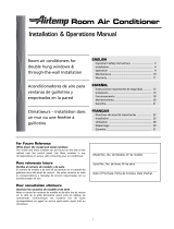
Installation & Operations Manual
Room air conditioners for
double hung windows &
through-the-wall Installation
Acondicionadores de aire para
ventanas de guillotina y
empotrados en la pared
ENGLISH
Important Safety Instructions .............................. 3
Installation .................................................................
Operation .............................................................. 9
Maintenance ....................................................... 10
Warranty .............................................................. 11
ESPAI_IOL
Instrucciones importantes de seguridad ........... _2
Instalaci6n ........................................................ 13
Funcionamiento ................................................. 18
Mantenimiento ............................................... 20
Garantia ................................................................ 21
Climatiseurs- Installation dans
un mur ou une fen_tre
guillotine
FRANCAIS
Directives de s_curit_ importantes .....................
Installation .................................................... 23
Utilisation ............................................................ 28
D_pannage ......................................................... 30
Garantie ............................................................... 31
For Future Reference
Write down the model and serial numbers
The model and serial numbers can be found on the side of the
cabinet near the control panel. Use these numbers in any
correspondence or service calls concerning your air conditioner.
Para referencia futura
Escriba el numero de modelo y de serie
El n0mero de modelo y de serie se encuentran en el costado del
gabinetecerca del panel de control. Use estos numerosentoda
la correspondencia o Ilamadas de servicio relacionadas con su
acondicionador de aire.
Model No., No. de Modelo, N° de modele
Serial No., No. de Serie, N° de s_rie
Date of Purchase, Fecha de Compra, Date d'achat
Pour consultation ult_rieure
Inscrivez les numeros de modele et de serie
Noter ci-contre les numeros de modele et de serie (on les trouve
sur le c6te de la grille decorative avant, pres du tableau de
commande). Communiquer ces numeros Iors de toute
correspondance ou appel au service apres-vente ayant trait au
climatiseur.
For additional questions please call
1-217-347-6459
Para mayor informacion por favor Ilame al
1-217-347-6459
o enviecorreo electronicoa:
Pour d'autres questions: 1.217.347.6459
ou courriel : [email protected]

_ INSTALLATIO N_'_
LECTRICAL REQUIREMENTS I
& SAFETY PRECAUTIONS J
Electrical Shock Hazard "_!_ &
• Plug unit only into grounded electrical outlet.
• Do not use an extension cord or plug adapter with this unit.
• Do not operate unit with decorative front or filter removed.
• Failure to follow these precautions could result in electrical
shock, fire or personal injury.
• If the air conditioner has a serial plate rating of 115 volts and
greater than 7.5 amps it must have its own fuse or circuit
breaker, and no other device or unit should be operated on
that fuse or circuit breaker. If the air conditioner has a serial
plate rating of 230 volts it must have its own fuse or circuit
breaker, and no other device or unit should be operated on
that fuse or circuit breaker.
• We recommend that a qualified electrician install unit in
accordance with the National Electrical Code and local codes
and ordinances.
• Do not operate this air conditioner without proper time delay
circuit protection. Refer to serial plate for proper power supply
requirements.
• Use copper conductors of correct wire gauge and
protector size only.
• Do not alter cord or plug end. Do not remove warning label
on cord.
Important Grounding Requirements
• Air conditioner has a three-prong grounding plug on the power
supply cord, which must be plugged into a properly grounded
three-prong wall receptacle for your protection against possible
shock hazard. For models up to and including 7.5 amperes use a
grounding type wall receptacle to match the cord plug.
• For models above 7.5 amperes use a single outlet grounding type
wall receptacle to match the cord plug.
Additional Safety Precautions
• Do not cut, alter or remove any of the expanded
polystyrene (white foam) inside this air conditioner.
• Do not store or use gasoline or other flammable vapors and
liquids in the vicinity of this or any other appliance. The
fumes can create a fire hazard or explosion.
• Do not introduce objects in the air discharge area. This
could cause permanent damage to your unit.
• Do not pour liquids on the air conditioner as this could
cause a malfunction. With the unit unplugged, use a damp
cloth for cleaning your unit.
• Avoid using strong solvents to clean the air conditioner.
• Clean the air conditioner filter every two weeks to avoid
overheating caused by air obstruction. Do not operate
without filter.
• Do not obstruct the air intake area of your air conditioner,
as this could cause overheating, thus activating the units
security switch and shutting off the unit.
• Do not block air circulation to outside louvers of cabinet.
• Do not block air flow inside with blinds, curtains, or
furniture, or outside with shrubs, enclosures, or other
buildings.
• Do not run the air conditioner with an outside protective
cover in place. This could result in fire or mechanical
damage within the air conditioner.
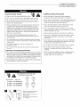
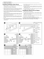
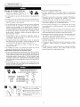
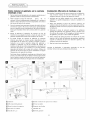
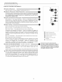
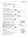
RECOMMENDED CIRCUIT WIRE SIZES
(As installed per building code) :
PROTECTORSIZE WIREGAUGE
15AMP #14 MINIMUM
20 AMP #12 MINIMUM
30 AMP #10 MINIMUM
©©
125V 250V
15A 20A
©©
250V 250V
15A 30A
Three-prong grounding plug.
Do not alter plug end.
Grounded three-prong wall
receptacle
Single outlet grounding wall
receptacle

iNSTALLATiON -'_
L vv, ovv,N+TA--ATONJ
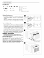
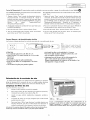
Tools Needed
® @
® ®
@ ®
(_ Blade-type screwdriver
@ Hammer
@ Rule or tape measure
@ Level
@ Knife
(_ Hex driver, ratchet or wrench
Window Requirements
1. Air conditioner is factory prepared for installation in standard double
hung window (air conditioner cannot be installed in other types of
windows without modification, consult with a qualified installation
serviceman).
2. Install the air conditioner in a window where there will be enough
clearance around the cabinet to allow ample circulation of air through
the unit.
3. All supporting parts should be secured to firm wood, masonry or metal.
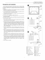
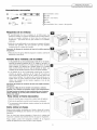
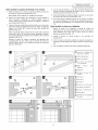
Unit & Window Size
1. If your air conditioner cabinet is 24 3/4" wide, it will fit window
openings 26" to 39" in width. Minimum opening height is 16" from
bottom of sash to sill. Removal of both filler panels permits installation
in windows with a minimum opening width of 24 5/8". Use foam seal
to fill any openings between the sides of the cabinet and the window
stop molding. This size unit requires two leveling brackets (Fig. 3a).
2. If your air conditioner cabinet is 26 1/2" wide, it will fit window
openings 27 7/8" to 40" in width. Minimum opening height is 18" from
bottom of sash to sill. Removal of both filler panels permits installation
in windows with a minimum opening width of 26 3/4". Use foam seal to
fill any openings between the sides of the cabinet and the window
stopmolding. This size unit requires two leveling brackets (Fig. 3b).
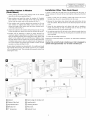
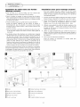
Decorative Front Removal
1. Remove the phillips screws on both sides of the cabinet (Fig. 4).
3. Gently pull forward while grasping both sides of the decorative front.
Removing the Chassis
Remove the two (2) antitheft screws from the side of the cabinet. RETAIN
THESE SCREWS,they will be replaced later in the installation (Fig. 4).
Slide the chassis out of the cabinet by grasping the front flange of the
evaporator cover and pulling forward while bracing the cabinet (Fig. 5).
Use caution when working around exposed sharp edges of the
cabinet and sharp coils to avoid injury or torn clothing.
u
lUl
Li !_
Z
'i 1i
_,emove screws from
both sides of cabinet
4

" INSTALLATION']
WINDOW INSTALLATON J
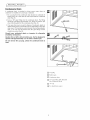
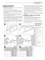
Installing Cabinet in Window
(Flush Mount)
1. Attach cabinet side seals to the existing holes in the cabinet
using the six (6) screws supplied (Fig. 6).
2. Open window and mark the center of window sill. Carefully
place cabinet in window and align center mark on the bottom
tie bar with the center mark on the window sill (Fig. 7).
3. Close window until it touches behind top retainer bar. Do not
close window so tightly that sliders cannot move. (Do not
release your grip on the cabinet until the lower window sash is
in its final position) (Fig. 7).
4. Attach the cabinet to the window sill by driving two (2) 1" long
screws through each cabinet track into the window sill (Fig. 8).
5. Brackets may be attached to cabinet in either direction for
maximum support, depending on the depth of the window sill.
Place the leveling bracket with leveling bolt under cabinet and
attach to the cabinet with two (2) #8 screws. Tighten screws
through cabinet into the smaller holes in the bracket. Placement
of bracket and screws to slots on cabinet track will depend on
size of the window sill. Position the brackets so bolts will rest
securely on window sill (Fig. 8 & 10).
Be sure cabinet maintains an outward pitch. Air conditioner should
slant slightly downward on the outside as shown by 1/2 a bubble
off on a carpenter's level. This outward pitch prevents water from
entering the room.
Installation Other Than Flush Mount
In order to install the unit with more of it projecting into the room, it
will be necessary to relocate the top retaining bar, side seals and bottom
tie bar.
1. Check to make sure the cabinet's outside side louvers will not be
blocked when the unit is moved farther into the room.
2. Remove the top retainer bar, cabinet side seals and bottom tie bar
from the cabinet. Relocate them for the desired projection into the
room.
3. Using the top retaining bar and cabinet side seals as templates,
locate and drill five (5) 7/32" mounting holes on the top of the
cabinet and three (3) on each cabinet side.
4. Use sealing material to fill the holes in the cabinet top and sides that
become exposed when the top retaining bar and cabinet side seals
were relocated.
5. Follow all preceding instructions.
Consult your authorized dealer or importer for alternative installation
instructions.
Caution: Do not drill a hole in bottom pan. Unit is designed to
operate with approximately 1/2" of water in bottom pan.
C) Cabinet
(_) Cabinet Side Seal
(_Top Retainer Bar
QWindow sill
C) 1" long screw
C) Outer edge of window sill
(_) Leveling bolt
C) Leveling bracket
(]) #8 screws
(_ Cabinet track

iNSTALLATiON
( vv, ovv,NSTA--ATONJ
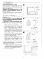
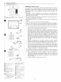
Installing the Window Filler Panels
1. Measure distance "X" between the face of the window stop
molding and the side of the cabinet (Fig. 11).
Note: Measure both sides of unit separately.
2. Subtract one groove (3/16") from "X" measurement to obtain the
required width. Using a sharp knife, score the groove until the
filler panel becomes weak enough to break apart (Fig. 12).
3. Insert cut edge of the filler panel into the cabinet side seal groove
(position 1). Leave a small space at the bottom of the cabinet side
seal groove (Fig. 13).
Rotate the filler panel backward toward the window frame until
the filler panel clears the window sill. Push the filler panel down
against the window sill (position 2).
Slide the filler panel out from the air conditioner cabinet until the
filler panel flange contacts the window stop molding (position 3)
(Fig. 14).
4. Attach the filler panel to the face of the window stop molding by
driving upholsterers' tacks through the holes in the filler panel
flange (Fig. 15).
5. Pull the sliders out until the sliders contact the face of the window
stop molding (Fig.16).
6. Pull bottom window sash down tightly and lock it in place by
installing a 5/8" long screw through the hole in the slider into the
window sash (Fig. 16).
7. Cut the plastic foam seal to proper length and insert it between
the upper and the lower window sash.
Installing the Chassis into the Cabinet
1. Slide the chassis into the cabinet.
2. To replace the front, place the top of the decorative front in
position and pivot back towards the unit and snap into place.
Replace screws and air filter.
3. Replace the two (2) antitheft screws at the bottom side of cabinet.
4. Use sealant to fill any minor openings.
5. Make sure unit is OFF, before plugging into the outlet.
Use caution when working around exposed sharp edges of the
cabinet and sharp coils to avoid injury or torn clothing.
iiiiiiiiiiiiiiiiiiiiiiiiiiiiiiiiiiiiiiiiiiiiiiiiiiiii
!
L
!
3--[ 1
9
(_ Face of window stop
molding
(&) Side of cabinet
C) Filler Panel
@ "X" minus one
groove (3/16")
(_ Cabinet side seal
(_ Cabinet
C) Window stop
molding
1_ Position 1
(_ Position 2
1_ Position 3
(_ Holes in flange
(_ Upholsterers' tacks
@ Hole in slider
(_ Slider
@ 1" long screw

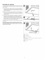
Through-the-wall Installation
This air conditioner is designed as a slide-out type chassis, making it possible
to install it through-the-wall in both existing and new construction. We
recommend that this type of installation be performed with professional
assistance.
• IMPORTANT: This appliance must be installed according to all applicable
electrical and building codes and ordinances.
• It is recommended that you have help to install your unit and that you use
proper lifting technique to avoid personal injury.
• It is important that you inspect the condition of the wall where the air
conditioner will be installed.
• Be sure the wall can support the weight of the unit.
• All cabinet louvers MUST BE on the outdoor side of the wall. DO NOT
BLOCK SIDE LOUVERS.
• The cabinet must be installed level from side-to-side and with a downward
tilt from inside to outside.
1. First remove the Decorative front panel and chassis from the cabinet,
then remove top bar from the cabinet.
2. Determine the size of the opening for a wood frame by adding 1/8" to
the width and height of the cabinet. Measure height from top of cabinet
to bottom of bar. Add this measurement to the thickness of wood used
to build the frame. This will determine the size of wall opening needed.
Minimum 1" thick lumber is recommended when building the frame.
When determining finish frame thickness, be sure not to cover side
louvers on the cabinet.
3. Install the finished frame in the wall opening square and level, nail or
screw it securely to the wall and place the cabinet into the framed wall
opening.
4. Make sure cabinet projects into the roomside of the wall 1 1/4" at the top
and 1 1/2" at the bottom to ensure proper tilt and access to the anti-theft
screw, then fasten cabinet to the frame by drilling twelve (12) 1" wood
screws (not supplied) through the cabinet and into the frame.
(Fig. 17 & 18).
If installation is made in a building with brick veneer construction, a steel
angle lintel must be used to support the bricks above the cabinet.(Fig.19)
5. Install a 3/4" X 1 1/2" wood filler strip between the bottom bar and the
interior, caulk both top and bottom of this strip. After cabinet is installed
caulk all openings, inside and outside between finish frame and cabinet
to prevent moisture from getting to the interior of the wall. Use of
flashing (driprail) will further prevent water from dripping inside
the wall.
6. Install chassis into cabinet.
(T INSTALLATIO N-"_
HRU-WALL INSTALLATION J
(_ Wood frame
(_ 1" wood screws
(_ Cabinet
Q Bottom Bar
(_ Interior wall
(_ Decorative Front
(_ Minimum lx6 wood
support (nailed or
screwed to wood
frame)
(_2" Wood frame
C)1 1/2" space
C)1 1/4" space
(_Brick veneer
C)Lintel angle
(_Caulking
(_Flashing (drip rail)
C)Side louvers
(_Wood filler strip

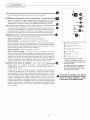
'"INSTALLATION-"]
Condensate Drain
A condensate drain is provided to divert excess water when air
conditioner is installed over a doorway or sidewalk.
1. Pry cap plug from the condensate drain (located on underside of
bottom pan). Use a 3/8" pipe tap and fully thread the condensate
drain (Fig. 20).
2. Screw a 3/8" pipe fitting into the condensate drain. The fitting
should be protruding approximately 1/2" above the bottom pan
when fully threaded into the condensate drain (Fig. 21).
3. If an open drain source is used to dispose of condensate, plastic or
rubber tubing may be run directly from the pipe fitting to the open
drain source. If closed drain source (internal structural plumbing) is
used, a "P" trap must be between the 3/8" pipe fitting and the
closed drain source (Fig. 22).
Consult your authorized dealer or importer for alternative
installation instructions.
Caution: Do not drill a hole in bottom pan. Unit is designed to
operate with approximately 1/2" of water in bottom pan.
Do not remove the cap plug, unless the condensate drain is
used.
0 Cap plug
0 Bottom pan
0 Condensate drain
0 3/8" pipe fitting fully threaded
into condensate drain
0 "P" trap
0 To closed drain source

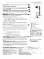
OPERATION --'}
Power Control
The Power Control turns the unit on and off,
Set Temperature/Timer Display
Shows the set temperature when the unit is in operation and hours when the timer is
being set. THE TEMPERATURE DISPLAY ONLY SHOWS THE SETTEMPERATURE, NOT THE
ACTUAL ROOM TEMPERATURE.
Temperature/Timer Hour Controls
These buttons are used to raise or lower the set temperature in increments of 1° from
66° to 88°. By depressing both buttons at once, the display will toggle between Celsius
and Fahrenheit. When the timer is being set, these buttons are used to change the hour
setting in increments of 1 from 00 to 24.
Mode Control O
A green light will indicate which mode is currently being utilized.
Cool Mode-The unit will circulate and cool the air.
Heat Mode (Heat Models Only)- The unit will circulate and heat the air.
Heater Safety Feature- When heater is powered off, low fan will automatically stay
on and run for 60 seconds to ensure the removal of residual heat, meanwhile, the
Low Fan LED blinks until the low fan stops.
Fan Mode- The unit will only circulate the air.
Energy Saver Mode - The fan will switch from the set fan speed to LOW whenever the
compressor turns off in response to the thermostat. When the compressor cycles back on,
the unit will return to the original fan setting.
Fan Speed Control
High, Medium*, Low and Auto *MEDIUM FAN NOT available on HEAT models.
The settings are adjusted with the Fan Speed Control, each time the button is depressed
it changes the setting. A green light will indicate which setting is currently being used.
When the AUTO feature is selected while the air conditioner is in the COOL or HEAT
mode, the fan speeds will change automatically as the temperature in the room changes.
COOL Mode
• 7° or more above the set temperature will use HI fan.
• 4° or less above the set temperature will use LO fan.
HEAT Mode (Heat models only)
• 9° or more below the set temperature will use HI fan.
• 4° or less below the set temperature will use LO fan.
Timer Control The timer can be set to either turn the unit on or off O
To turn the unit ON using the Timer: Depress the timer key when the power is off,
the display will read 00. Adjust to the desired number of hours before TURN ON using the
up/down arrows.The display will show the time by hours left until TURN ON. To Turn the
timer off, depress the timer key. A green light next to the Timer Control indicates that the
timer isset.
To turn the unit OFF using the Timer: Depress the timer key when the power is on,
the display will read 00. Adjust to the desired number of hours before TURN OFF using
the up/down arrows. The display will automatically return to the set temperature after 10
seconds.To display the amount of time left until TURN OFF,depress the timer button once.
To turn the TIMER OFF, depress the timer button twice. A green light next to the Timer
Control indicates that the timer is set.
®
®
" MEOO®
® HIGH • AUTO
ENERGY
• COOL ® FAN @
ON/OFF
®
Power Control
Temperature/Timer Display
lemperature/Timer Controls
Mode Control
Fan Speed Control
Timer On/Off
Built-in three minute timing delay.
This electronic controlled unit will
not automatically resume operation
after a power failure.
ff this electronic unit will not respond
to touch pad or remote control
commands, it is necessary to unplug
the unit from the electrical outlet for
five seconds and then plug the unit
back in.
_ he heat from this unit is designed
only as a supplemental heat
source in addition to
regular heating systems.
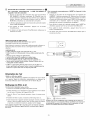
Air Conditioner Remote Control /_ _
the on t,ons orkthes0 e0s oor0,r on ,t,oner'stoo h on,o.s."'0""'"/o_
CAUTION: • Do not install the k_______
• Use only AAA or IEC R03 1.5V batteries.
• Remove the batteries if the remote controller is not
used for a month or longer.
• Do not attempt to recharge the supplied batteries
• All batteries should be replaced at the same time.
• Do not dispose of the batteries in a fire as they may
explode.
• Do not mix old and new batteries.
batteries with the
polarity (+/-)
reversed.
• Do not mix alkaline, standard (carbon - zinc), or
rechargeable (nickle-cadmium) batteries.
• Keep batteries and other things that could be
swallowed away from young children. Contact
a doctor immediately if an object is swallowed.
o

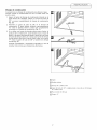
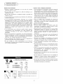
Directing Airflow
Unit is engineered with adjustable louvers to direct discharge airflow.
Louvers are manually adjusted by moving levers in direction of desired
airflow (Fig. 23).
Cleaning Air Filter
EVERY TWO WEEKS: Clean the filter.
1. Turn Master Control to OFF.
2. Remove the air filter by grasping the top corners and pulling it up
and out of the unit (Fig. 23).
3. Wash in hot soapy water, rinse and shake dry.
4. Replace the filter, with the front of the filter toward you.
5. To dry the filter thoroughly, run your unit for a few minutes.
Remember, only a clean filter works properly and delivers top
efficiency at every setting.
(_ Filter (Z) Louvers
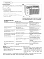
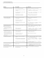
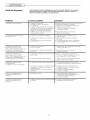
Troubleshooting Guide
Occurrence
Air conditioner will not operate
Air from unit does not feel
cold enough
Air conditioner cooling, but room is too
warm-- ice forming on cooling coil
behind decorative front
Air conditioner cooling, but room is too
warm-- no ice forming on cooling coil
behind decorative front
Noise when unit is cooling
Water dripping inside when unit is
cooling
Water dripping outside when unit is
cooling
Note: Failure to keep air filter clean will result in poor air circulation,
DO NOT operate without filter, This can render the unit inoperative,
Possible Cause
• Wall plug disconnected.
• House fuse blown or circuit breaker tripped,
• Unit turned off and then on too quickly.
• Adjust thermostat to lower temperature.
• Unit in Fan mode.
• Temperature set too high.
• Room temperature below 70°F.
• Outdoor temperature below 70°F.
• Dirty air filter -- air restricted.
• Dirty air filter -- air restricted.
• Thermostat set too warm.
• Air movement sound.
• Sound of fan hitting water-moisture removal
system.
• Window vibration -- poor installation.
• Improper installation.
• Unit removing large quantity of moisture from
humid room.
Solutions
Push plug firmly into wall outlet.
Replace fuse with time delay type
or reset circuit breaker.
Wait 3 minutes before restarting.
Adjust thermostat to lower temperature.
• Set Mode to Cool.
• Set thermostat to lower temperature.
• Cooling may not occur until room
temperature rises above 70°F.
To defrost the coil, set mode to Fan.
Then, set thermostat to warmer
temperature.
Clean filter. See "Cleaning the Air
Filter"section. To defrost, set mode to Fan.
• Clean air filter.Refer to "Cleaning Air Filter"
section.
• Set thermostat to colder temperature.
The sound of rushing air is normal.
If too loud, Fan Speed to Low setting.
This is normal when humidity is high.
Close doors, windows and registers.
Refer to installation instructions -- check
with installer.
• Tilt air conditioner slightly to the outside to
allow water drainage. Refer to installation
instructions -- check with installer.
This is normal during excessively
humid days.
Service To save time and expense, check the following before calling an authorized service station.
Insufficient Cooling
• Shut all windows and doors in room.
• Remove any obstructions from inside and outside louvers.
• Inspect filter and clean if dirty.
• Under certain conditions the cooling coils directly behind
the filter, may ice up and block the airflow. This is a
common occurrence in air conditioners caused when the
outside temperature drops below 70°F (21°C) while the
humidity remains high. If this happens, simply turn the unit
off and allow the ice to melt, then resume normal
operation.
Proper use and care of your air conditioner will help ensure longer fife of the unit. It is recommended to annually inspect and clean
the coils and condensate water passages. Expense of annual inspection is the consumer's responsibility.
10

How to Obtain Warranty Service or Parts
Note: Before calling for service, carefully read the Installation and
Operating Instructions booklet. Then if you need service:
1. Call a CareCo authorized servicer and advise them of model
number, serial number, date of purchase and nature of complaint.
Service will be provided during normal working hours.
Contact your dealer for the name of an authorized servicer, if
unknown to you.
2. If your dealer is unable to give you the name of a servicer or if you
need other assistance, call the following toll-free number for the
name of an authorized servicer or authorized parts distributor:
1-800-332-6658
or you may write:
CareCo, Service Department
415 W.Wabash Ave., P.O.Box 200
Effingham, IL 62401
Proofof PurchaseDate
It is the responsibility of the consumer to establish the original
purchase date for warranty purposes. We recommend that a bill of
sale, cancelled check, or some other appropriate payment record be
kept for that purpose.
/" SERVICE & -"_
WARRANTY J
Room Air Conditioner Warranty
(Within tile 48 contiguous United .States, state of Hawaii, tile District of
Columbia, Puerto Rico and Canada)
Full (One Year) Parts and Labor Warranty
During the first year after the date of original purchase, Fedders
Appliances will, through its authorized servicers and free of charge to
the owner or any subsequent user, repair or replace any parts which are
defective in material or workmanship due to normal use. Ready access
to the air conditioner for service is the responsibility of the owner.
Limited (Five Year) Sealed SystemWarranty/
(Two Year) Fan Motor Parts Warranty
In addition to the full (one year) parts and labor warranty described
above, Fedders Appliances will, through its authorized servicers or
parts distributors, exchange sealed system parts (consisting of
compressor, evaporator, condenser, and interconnecting tubing) during
the second year through fifth year, and the fan motor during the
second year, both from the original date of purchase, providing the
parts are defective in material or workmanship. Transportation,
handling, or labor costs to diagnose, repair or replace such defective
parts are not covered by this limited parts warranty and are the
owner's responsibility.
Note: In the event of any required parts replacement within the period of this
warranty, Fedders Appliances replacement parts shall be used and will be
warranted only for the period remaining on the original warranty,
Exceptions
The above warranty does not cover failure to function caused by
damage to the unit while in your possession (other than damage
caused by defect or malfunction), or by its improper installation, or by
unreasonable use of the unit, including without limitation, failure to
provide reasonable and necessary maintenance or to follow the
written Installation and Operating Instructions. If the unit is put to
commercial, business, rental, or other use or application other than for
consumer use, we make no warranties, express or implied, including
but not limited to, any implied warranty of merchantability or fitness
for particular use or purpose.
THE REMEDIES PROVIDED FOR IN THE ABOVE EXPRESS
WARRANTY ARE THE SOLE AND EXCLUSIVE REMEDIES
THEREFOR, NO OTHER EXPRESS WARRANTIES ARE MADE. ALL
IMPLIED WARRANTIES, INCLUDING BUT NOT LIMITED TO ANY
IMPLIED WARRANTY OF MERCHANTABILITY OR FITNESS FOR A
PARTICULAR USE OR PURPOSE, ARE LIMITED IN DURATION TO
ONE YEAR FROM THE DATE OF ORIGINAL PURCHASE. IN NO
EVENT SHALL FEDDERS APPLIANCES BE LIABLE FOR INDIRECT,
INCIDENTAL, OR CONSEQUENTIAL DAMAGES, EVEN IF
ADVISED IN ADVANCE OF THE POSSIBILITY OF SUCH
DAMAGES. NO WARRANTIES, EXPRESS OR IMPLIED, ARE MADE
TO ANY BUYER UPON RESALE.
Some states do not allow limitations on how long an implied warranty
lasts or do not allow the exclusion or limitation of incidental or
consequential damages, so the above limitations or exclusions may not
apply to you. This warranty gives you specific legal rights, and you may
also have other rights which may vary from state to state.
No warranties are made for units sold outside of the above stated
areas. Your distributor or final seller may provide a warranty on units
sold outside of these areas.
11

"_nFEnINSTALAC I©N --'_
QUERIMIENTOS ELECTRIGOS Y I
ECAUCIONES DE SEGURIDAD )
RiesgodeChoqueElectrico _ _
• Enchufe el aparato solamente en un
tomacorriente electrico puesto a tierra.
• Con este aparato no use un cordon de extensi6n ni un adaptador de
enchufe.
• No haga funcionar el acondicionador de aire sin el panel delantero.
• El incumplimiento de estas precauciones pueden causar un choque
electrico, incendio o lesi6n personal.
• Si el acondicionador de aire tiene una potencia nominal indicada en
la placa de serie de 115 voltios y de mas de 7,5 amperes, es
necesario que sea protegido con su propio fusible o disyuntor y
ningOn otro dispositivo debe usar ese mismo disyuntor o fusible. Si
el acondicionador de aire tiene una potencia nominal en la placa
de serie de 230 voltios, es necesario que sea protegido con su
propio fusible o disyuntor y ningOn otro aparato debe usar ese
mismo disyuntor o fusible.
• Recomendamos que un electricista calificado instale el
acondicionador de aire de acuerdo con el codigo electrico nacional
y los codigos y reglamentos locales.
• No haga funcionar este acondicionador de aire sin protecci6n
adecuada del circuito de retardo. Consulte la placa de serie para
los requerimientos apropiados de alimentaci6n electrica.
• Use solamente conductores de cobre y fusibles de calibre y
capacidad adecuada.
• No modifique el cordon ni el enchufe del extremo. No retire la
etiqueta de advertencia del cordon de alimentaci6n.
Requerimientos Importantes para la Puesta a Tierra
• El cord6n de alimentaci6n del acondicionador de aire tiene un enchufe
de tres clavijas con puesta a tierra el cual debe ser enchufado en un
tomacorriente mural puesto a tierra de tres alveolos para su protecci6n
contra posible riesgo de choque electrico. Para los modelos de hasta
7,5 amperes o menos, use un tomacorriente mural del tipo con puesta
a tierra que tenga la misma configuraci6n que el enchufe del cord6n de
alimentaci6n.
• Para los modelos de mas de 7,5 amperes, use un tomacorriente mural
sencillo con puesta a tierra que tenga la misma configuraci6n que el
enchufe del cord6n de alimentaci6n.
Precauciones de Seguridad Adicionales
• No corte, modifique ni retire ning0n pedazo de poliestireno
expandido (espuma blanca) situado dentro de este acondicionador
de aire.
• No guarde ni use gasolina u otros vaporesy liquidos inflamables en
la vecindad de este o cualquier otro artefacto. Los vapores
emitidos pueden crear un riesgo de incendio o explosi6n.
• Nointroduzca objetosen elareadedescargadelaire. Esto puede
causar da_o irreparable a su acondicionador de aire.
• No vierta liquidos de limpieza en el acondicionador de aire pues
esto puede causar un malfuncionamiento. Use un paso hOmedo
para limpiarlo.
• Evite usar solventes fuertes para limpiar el acondicionador de aire.
• Limpie el filtro del acondicionador de aire cada dos semanas para
evitar sobrecalentamiento causado por obstrucci6n del aire.
• No obstruya el area de entrada del aire de su acondicionador, pues
esto puede causar sobrecalentamiento, Io cual activara el
interruptor de seguridad y apagara el aparato.
• No bloquee la circulaci6n del aire hacia las rejillas de ventilaci6n
exteriores del gabinete.
• No obstruya el flujo del aire hacia el interior con persianas, cortinas
o muebles o hacia el exterior con arbustos, recintos u otros
edificios.
• No haga funcionar el acondicionador de aire teniendo instalada la
cubierta protectora exterior. Esto podria resultar en da_o
mecanico dentro del acondicionador de aire.
CAPAClDAD DE
LOS FUSIBLES
15AMP
20 AMP
30AMP
TAMANOS RECOMENDADOS DE LOS
CONDUCTORES DEL ClRCUITO
(Instalados segOn el c6digo de construcci6n) •
© ©
CALIBRE DE LOS 125v 250v
CONDUCTORES 15A 20A
#14 COMO MINIMO (_ (_
#12 COMO MINIMO
#10 COMO MINIMO
250v 250v
15A 30A
C)Enchufe de tres clavijas con
puesta a tierra. No Modifique.
Tomacorriente para enchufe de
tres clavijas conpuesta a tierra.
Tomacorriente mural sencillo con
puesta a tierra.
12

INSTALACION
STALACIDN EN LA VENTANA }
Herramientas necesarias
C) .......... O (_) Destomillador co mL'm
(_)Martillo
(_ (_ (_}Regla o cinta m6trica
(_Nivel
(_ Destomillador, Ilave o matraca hexagonales
Requisitos de la ventana
1.El acondicionador de aire se prepara en la fabrica para una
instalaci6n estandar en ventanas de guillotina (los acondicionadores
de aire no pueden instalarse en otros tipos de ventanas sin
modificarlas -- para hacer esto hay que consultar a un instalador
calificado).
2.1nstale el aire acondicionado en una ventana con espacio suficiente
alrededor del gabinete, esto para permitir que haya bastante
circulaci6n del aire a traves de la unidad.
Precaucion: No bloquee la circulacion del aire de las rejillas exteriores
del gabinete.
3.Todas las piezas de apoyo deberan asegurarse a madera, material de
albaffileria o metal firme.
Tama_o de la ventana y de la unidad
1.Si el gabinete de su aire acondicionado mide 26 1/2" de ancho,
entonces se ajustara a aberturas de 27 7!8" hasta 40" de ancho. La
altura minima de la abertura es 18" desde la parte inferior del marco
hasta el alfeizar. Si la abertura de la ventana donde se va a instalar
tiene un ancho minimo de 26 3/4" quite los paneles de relleno. Las
unidades de este tamaffo requieren el uso de un soporte nivelador.
2. Si el gabinete de su aire acondicionado mide 24 3/4" de ancho,
entonces se ajustara a aberturas de 26" hasta 39" de ancho. La
altura minima de la abertura es 16 1/4" desde la parte inferior del
marco hasta el alfeizar. Si la abertura de la ventana donde se va a
instalar tiene un ancho minimo de 24 5/8" quite los paneles de
relleno. Las unidades de este tamaffo requieren el uso de dos
soportes niveladores.
Precaucion: No bloquee la circulacion del aire de las rejillas exteriores
del gabinete.
No obstruya el flujo de aire en el interir con persianas, cortinas o
muebles; o en el exterior con arbustos, cercas u otras construcciones.
No haga funcionar el aparato de aire acondicionado con el protector
exterior instalado, ya que esto podria ocasionar da6os mecanicos
dentro de la unidad.
Para retirar el frente decorativo
1. Retire los tornillos que se encuentran a ambos lados del gabinet.
2. Quite las dos perillas de control (control mecanico solamente).
3. Tire suavemente hacia adelante mientras sostiene los dos lados del
frente decorativo.
C6mo retirar el chasis
Quitar los dos tornillos, Iocalizados en el fondo y frente de la careta.
GUARDE ESTOS TORNILLOS, ellos deberan ser colocados de nuevo en la
instalaci6n.
Corra el chasis hacia afuera sujetando el frente de la cubierta del
evaporador y halando hacia delante mientras se apoya en el gabinete.
Tenga cuidado cuando este trabajando alrededor de las esquinas
afiladas del gabinete para evitar heridas o ropas rasgadas.
U
D
/ ZZZZZZZZZZZZZZZZZZZZZ
13

(_N NSTALACION --"_
STALACIDN EN LA VENTANA J
C6mo instalar el gabinete en la ventana
(montaje a ras)
1. Fije los sellos lateral del gabinete a los agujeros existentes en el
gabinete usando los seis (6) tornillos suministrados.
2. Abrir la ventana y marcar el centro del quicio de la
ventana. Colocar cuidadosamente el gabinete en la ventana y
alinear la marca del centro en la barra separadora con la marca
del centro del quicio de la ventana.
3. Cerrar la ventana hasta que toque la parte de atras de la barra
de retenci6n superior. No cerrar la ventana tan apretadamente
que no se puedan mover las deslizadoras. (No soltar el gabinete
hasta que el bastidor inferior de la ventana este en su posici6n
final).
4. Monte el gabinete al antepecho de ventana con dos (2)
tornillos de una pulgada insertados a traves de cada carril del
gabinete asegurandolos dentro del antepecho de ventana.
5. Se puede acoplar los soportes al gabinete en cualquier
direcci6n para Iograr un maximo apoyo, dependiendo de la
profundidad de la repisa de la ventana. Coloque el soporte
nivelador con el perno nivelador debajo del gabinete y
acoplelos al gabinete con dos (2) tornillos #8. Apriete los
tornillos a traves de los orificios mas pequeffos en el soporte. La
colocaci6n del soporte y los tornillos en el riel del gabinete
dependera del tamaffo de la repisa de la ventana. Coloque los
soportes de tal manera que los pernos niveladores se apoyen
firmemente en la repisa de la ventana.
Cerci6rese de que el gabinete mantenga una inclinaci6n hacia
afuera. El acondicionador de aire debera inclinarse ligeramente
hacia el exterior usando la indicaci6n de un nivel de carpintero.
Dicha inclinaci6n evitara que el agua entre en la habitaci6n.
Instalaci6n diferente al montaje a ras
Para instalar la unidad de modo que se proyecte en la habitaci6n,
sera necesario reubicar la barra de retenci6n superior, los
selladores laterales, y la barra de separaci6n inferior.
1. Verifique que las rejillas laterales de la parte exterior del
gabinete no queden bloqueadas al colocar la unidad en la
habitaci6n.
2,
Retire del gabinete la barra de retenci6n superior, los
selladores laterales del gabinete y la barra separadora inferior.
Reubiquelos hasta encontrar la proyecci6n deseada dentro de
la habitaci6n.
3. Utilizando la barra de retenci6n superior y los selladores
laterales del gabinete como plantillas, ubique y perfore cinco
(5) orificios de montaje de 7/32 pulgada en la parte superior
del gabinete y tres (3) en cada costado del gabinete.
4. Utilice material de sellar para Ilenar los orificios de la parte
superior y de los lados del gabinete que quedaron expuestos
cuando se reubicaron la barra de retenci6n superior y los
selladores laterales del gabinete.
5. Siga las instrucciones precedentes.
Consulte al distribuidor o importador autorizado en caso de
necesitar instrucciones para instalaciones alternativas.
(_ Gabinete
(_ Sello lateral del gabinete
1_) Barra de retenci6n superior
(]_)Quicio de la ventana
(_)Tornillo de 1 po
(_ Borde exterior de la repisa de la ventana
(_) Perno nivelador
(_ Soportes niveladore
(_ Tornillos #8
C) Riel del gabinete
14

_N INSTALACION
STALACIDN EN LA VENTANA )
C6mo instalar los paneles de Ilenado en la ventana
1. Medir la distancia "X" entre la cara de la moldura de tope de
la ventana y el lado del gabinete (Fig. 10).
Nota: Medir ambos lados de la unidad por separado.
2. Reste una muesca (3/16") de la medici6n "X" para obtener el
ancho necesario. Utilizando un cuchillo afilado, raspe la
muesca hasta que el panel de Ilenado se debilite Io suficiente
para desprenderlo (Fig. 11).
3. Insertar el borde cortado del panel de relleno en la ranura de
sellar del costado del gabinete (posici6n 1). Dejar un peque_o
espacio en la base de la ranura de sellar del costado del
gabinete (Fig. 12).
Rotar el panel de relleno hacia atras en el marco de la ventana
hasta que el quicio de la ventana quede despejado. Empujar
el panel de relleno hacia abajo contra el alfeizar de la ventana
(posici6n 2) (Fig. 13).
Deslizar el panel de relleno sacandolo del gabinete del
acondicionador de aire hasta que el reborde del panel de
relleno haga contacto con la moldura de tope de la ventana
(posici6n 3) (Fig.13).
4. Unir el panel de relleno a la cara de la moldura de tope de la
ventana clavando tachuelas de tapicero en los orificios del
reborde del panel de relleno (Fig. 14).
5. Sacar las deslizadoras hasta que hagan contacto con la cara de
la moldura de tope de la ventana (Fig. 15).
6. Tirar hacia abajo el bastidor inferior de la ventana y trabarlo
en su lugar instalando un tornillo de una pulgada de largo por
el orificio de la deslizadora en el bastidor de la ventana (Fig.
16).
C6mo instalar el chasis en el gabinete
1. Deslice el chasis en el gabinete e inserte el cord6n de
alimentacion en la muesca del gabinete. Cerci6rese de que la
parte delantera del chasis este al mismo nivel de la parte
delantera del gabinete (Fig. 17).
2. Vuelva a colocar el panel frontal y los tornillos de
acoplamiento.
3. Corte el largo correcto del sellador de espuma de plastico e
insertelo entre el bastidor de ventana superior e inferior (Fig.
18).
4. Usar el sellador proveido para Ilenar peque_as aberturas.
i@
1_ Cara de la moldura de
tope de la ventana
C) Lado del gabinete
C) Panel de relleno
(_"X" menos una ranura
(3/1 6 pulgada)
C) Sello lateral del
gabinete
{_ Gabinete
(_ Moldura de tope de la
ventana
(_ Posici6n 1
(_ Posici6n 2
C) Posici6n 3
(_ Orificios en el reborde
(_ Tachuela de tapicero
(_ Orificio en deslizadora
(_ Deslizadora
(_ Tomillo de una pulgada
de largo
15

f INSTALACION "_
INSTALAGION EMPOTRADD
EN LA PARED
Instalacion Empotrado en la Pared
Este acondicionador de aire ha sido diseffado como un chasis
deslizable, haciendo que sea posible su instalaci6n empotrado
en la pared, tanto en muros de construcci6n antigua como
moderna. Recomendamos que este tipo de instalaci6n sea
realizado con ayuda profesional.
• IMPORTANTE: Este aparato debe ser instalado de acuerdo
con todos los codigos y reglamentos electricos y de
construccion aplicables.
• Se recomienda que usted solicite ayuda para instalar el
aparato y que use una tecnica de alzamiento adecuado para
evitar lesion personal.
• Es importante que usted inspeccione el estado de la pared
donde se instalara el acondicionador de aire.
• Asegurese de que la pared pueda soportar el peso del
acondicionador de aire.
• Todas las rejillas de ventilaci6n del gabinete DEBEN QUEDAR
hacia el lado exterior de la pared. NO BLOQUEE LAS REJILLAS
DE VENTILACION LATERALES.
• El gabinete debe ser insta/ado de modo que quede hive/ado
de lado a lado y con una ligera inclinacion hacia abajo desde el
interior al exterior.
1. Retire primero el panel decorativo delantero y el chasis del
gabinete. Retire la barra superior del gabinete.
2. Determine el tama6o de la abertura para construir un marco
de madera agregando 1/8" al ancho y a la altura del
gabinete. Mida la altura desde la parte superior del
gabinete hasta la barra inferior. Agregue esta medidas al
grosor de la madera usada para construir el marco. Esto
determinara el tama6o necesario de la cavidad en la pared.
El marco debe construirse usando madera de por Io menos
1" de espesor. Cuando se determine el grosor del marco
acabado, asegOrese de que este no cubra las rejillas de
ventilaci6n laterales del gabinete.
3. Instale el marco terminado en la cavidad mural de manera
que quede a escuadra y nivelado, luego clavelo o atornillelo
firmemente en la pared e introduzca el gabinete en la
cavidad mural ya preparada con el marco.
4. AsegOrese de que el gabinete sobresalga de la pared 1-1/4"
en la parte superior y 1-1/4" en la parte inferior hacia la
habitaci6n para asegurar una inclinacion adecuada y acceso
al tornillo antirrobo, luego asegure el gabinete en el marco
instalando doce (12) tornillos de madera de 1" (no
suministrados) a traves de los agujeros taladrados en el
gabinete y hacia el marco.
Si el acondicionador se instala en un muro enchapado de
ladrillo se debe usar un dintel angular de acero para sostener los
ladrillos que estan arriba del gabinete.
5. Una vez que se haya instalado el gabinete obture todas las
aberturas en el interior y exterior entre el marco acabado y
el gabinete para evitar que la humedad penetre al interior
de la pared. El uso de un guardaaguas (vierteaguas) ayudara
tambi_n a evitar que el agua gotee dentro de la pared.
6. Instale el chasis en el gabinete.
(_ Marco de madera
(_ Tornillos de madera de 1"
(_ Gabinete
O Barra inferior
(_ Marco de madera de
2" por todo el rededor
(_ Espacio de 1-1/2"
(_ Espacio de 1-1/4"
1_} Pared (_ Enchapado de ladrillo
(_ Panel decorativo delantero 1_ Dintel angular
(_ Soporte de madera de por (_ Material obturador
Io menos 1 x 6 (clavado o (_ Guardaaguas
atornillado en el marco de (Vierteaguas)
madera) G) Rejillas de ventilacion
1_ relleno de madera
16

¢ INSTALACI©N _-")
Drenaje de condensaci6n
Se proporciona un drenaje de condensaci6n para desviar el agua
excesiva cuando el acondicionador de aire se instala sobre una
puerta o acera.
1. Separar el tap6n del drenaje de condensaci6n (ubicado en la
parte inferior de la bandeja). Utilizar un conector de tubo de
3/8" y enroscar completamente el drenaje de condensaci6n
(Fig. 20).
2. Atornillar un ajuste de tubo de 3/8" en el drenaje de
condensaci6n. El ajuste debera sobresalir aproximadamente
1/2" sobre la bandeja inferior cuando este completamente
enroscado en el drenaje de condensaci6n (Fig. 21).
3. Si se utiliza una fuente de drenaje abierta para eliminar el
producto de la condensaci6n, podra hacerse pasar un tubo de
plastico o de goma directamente desde el ajuste de tubo hasta
la fuente de drenaje abierta. Si se utiliza una fuente de drenaje
cerrada (tuberia estructural interna), deber haber una trampa
"P" entre el ajuste de tubo de 3/8" y lafuente de drenaje
cerrada (Fig. 22).
Consulte al distribuidor o importador autorizado en caso de
necesitar instrucciones para instalaciones alternativas.
C) Tap6n
C) Bandeja inferior
(_ Drenaje de condensaci6n
(_)Ajuste de tubo de 3/8" completamente enroscada en el drenaje
de condensaci6n
(_ Hacia fuente de drenaje
(_ Trampa "P"
17

FUNCI©NAMIENTO-"_
PANEL DE CONTROL ELECTRONIC®
(_) Control de Alimentaci6n
Este boton pone en marcha y apaga el acondicionador de aire.
(_ Indicador de Temperatura de AjustelTemporizador
El indicador muestra la temperatura de ajuste cuando el acondicionador de aire esta
en funcionamiento y las horas cuando se ha activado el temporizador. EL INDICADOR
DE LA TEMPERATURA SOLAMENTE MUESTRA LA TEMPERATURA DE AJUSTE, NO LA
TEMPERATURA AMBIENTE REAL.
O Control de la Temperatura/Temporizador
Estos botones se usan para aumentar o reducir la temperatura de ajuste en
incrementos de 1°, entre 66°F hasta 88°1:. Si se oprimen simultaneamente ambos
botones, el indicador digital cambiara entre grados Celsius y Fahrenheit. Cuando se
activa el temporizador, estos botones son usados para cambiar el ajuste de la hora en
incrementos de 1, entre 00 hasta 24.
(_) Selector de Modo 0
Una luz verde indicara el modo que esta siendo utilizado.
Modo 'Cool' (Frio) - El acondicionador de aire circula y enfria el aire.
Modo'Heat'(Calor)- Elacondicionadordeairecirculaycalientaelaire.
Caracteristica de Seguridad del Calentador - Cuando el calentador esta apagado, el
ventilador de baja velocidad se activara y funcionara durante 60 segundos para
asegurar la eliminaci6n de alg0n calor residual, a la vez que el diodo LED 'Low Fan'
(ventilador de baja velocidad) destella hasta que se detenga el ventilador de baja
velocidad.
Modo 'Fan' (Ventilador) - El acondicionador de aire solamente hara circular el aire.
Modo 'Energy Save' (Ahorro de Energia) -
(El modo de ahorro de energia esta dise_ado para funcionar solamente con el modo
'Cool'). El ventiladorcambiara de la velocidad deajuste a velocidad baja cuando el
compresor sea apagado por el termostato. Cuando el compresor se activa
nuevamente, el ventilador volvera al ajuste original. La velocidad del ventilador
cambia automaticamente seg0n cambie la temperatura en la habitaci6n.
(_ Control de la Velocidad del Ventilador - Alta, Baja y Automatica
El ajuste de la velocidad del ventilador se cambia cada vez que se ®prime el boton de
control de velocidad del ventilador. Una luz verde indicara el ajuste que se ha
seleccionado.
Cuando se selecciona 'Auto' (Automatic®) y el acondicionador de aire esta en el modo
'Cool' o 'Heat', la velocidad del ventilador cambiara automaticamente a medida que
O cambie la temperatura en la habitaci6n. En el modo 'Cool', cuando la habitaci6n Ilega
a 7 ° o mas, sobre la temperatura de ajuste, se usa 'High Fan' (Alta Velocidad), cuando
la temperatura en la habitaci6n es de 7 ° o men®s, sobre la temperatura de ajuste, se
usa 'Low Fan'(Velocidad Baja). Enel modo'Heat'cuandola habitaci6nalcanza7 °o
mas, bajo la temperatura de ajuste, se usa 'High Fan', cuando la habitaci6n alcance
7° o men®s, bajo la temperatura de ajuste, se usa 'Low Fan'.
®
®
©
® Control de alimentaci6n
® Pantalla de temperatura/hora
® Controles de temperatura/hora
® Control de modo
® Control de la velocidad del
ventilador
C) Control del reloj
Mecanismo de retraso de tresminutos incorporado
Es_teaparato controlado electr6nlcamente reanudar_ su
operaci6n despt_s de la intermpci6n del serviclo eld_rico.
Si este aparato electr6nlco no responde a los mandos del
control remoto o cojlnete t_ctil,ser_necesarlodesenchtdarlo
clnco segundosy loego volver a enchufar
18

# SERVICIO
SOLUCION DE AVERIAS
A
Control del
Temporizador (El temporizador puede ser ajustado ya sea para encender o apagar el acondicionador de aire.)_,,,IMMMm_
Para PONER EN MARCHA automaticamente el acondicionador Para APAGAR automaticamente el acondicionador de aire usando el
de aire usando el modo 'Timer': modo 'Timer':
1. Oprima el boton 'Timer' cuando la alimentaci6n electrica
este desconectada. El indicador mostrara 00. Ajuste el
indicador para que muestre el n0mero de horas que desea
que transcurran antes de la PUESTA EN MARCHA, usando las
flechas de ajuste 'Temperature/Timer'
(Tern peratura/Temporizador).
2. El indicador mostrara la cantidad de horas que faltan para
la PUESTA EN MARCHA.
3. Para salir del modo 'Timer', oprima el boton 'Timer'.
4. Una luz verde situada junto al boton 'Timer' se iluminara
para indicar que el 'Timer' esta activado.
1. Oprima el boton 'Timer' cuando la alimentaci6n electrica este
conectada. El indicador mostrara 00. Ajuste el indicador para que
muestre el n0mero de horas que desea que transcurran antes de
que se APAGUE usando las flechas de ajuste 'Temperature/Timer'
(Temperatura/Temporizador). (Despues de 10 segundos, el
indicador volvera automaticamente a la temperatura de ajuste.)
2. Para ver la cantidad de horas que faltan para que se APAGUE el
acondicionador de aire, oprima una vez el boton 'Timer'.
3. Para salir del modo 'Timer', oprima el boton 'Timer' dos veces.
4. Una luz verde situada junto al boton 'Timer' se iluminara para
indicar que el 'Timer' esta activado.
Control Remoto de Acondicionador de Aire
Las funciones trabajan igual que los controles manuales de su acondicionador de aire.
®_ i___
Pilas:
o \1 Retire al tapa en la parte trasera del
control remoto e inserte las baterias
o con los polos (+) y (-) en la direcciOn
correcta,
ATENCION
• Use solabente pilas AAA o IEC R03 de 1,5V.
• Retire/as pilas si el control remoto no va a set usado
durante un
mes o m_s.
• No intente recargar las pilas sumh_istradas.
• Todas las pilas deben set reemplazadas a un mismo
tiempo.
• No incrinere las pilas pues pueden explotar.
• No instale las pilas con la polaridad (+/-) inversa.
• No mezcle pilas alcalinas, standard (carbon-zinc), con
pilas recargables (nickel-cadium).
• Mantenga fuera del alcance de los ni_os peque_os las
pilas y otros artfculos que puedan set tragados.
P6ngase inmediatamente en contacto con un m_dico si un
ni_o peque_o se traga un objeto.
Orientacibn de la corriente de aire
La unidad viene equipada con rejillas directrices ajustables que permiten
dirigir la descarga de la corriente de aire. Las rejillas pueden ajustarse
manualmente moviendo las palancas en la direcci6n deseada (Fig. 23).
Limpieza del filtro de aire
CAD?, DOS SEMANAS: Limpie el fikro.
1. Ponga el control maestro en posici6n apagado.
2. Para retirar el filtro de aire, sujetelo de las esquinas superiores y
remuevalo hacia arriba y hacia afuera (Fig. 23).
3. Lavelo con agua caliente enjabonada, enjuaguelo, sacudalo y
sequelo.
4. AI ponerlo de nuevo en su lugar, aseg0rese que el lado frontal
quede mirando a usted.
5. Para secar bien el filtro, haga funcionar la unidad durante unos
minutos. Recuerde, que solo un filtro limpio hara funcionar su
unidad correctamente y dara siempre el servicio mas eficiente.
Advertencia: El no mantener limpio el filtro podria resultar en baja circulaci6n de/aire.
NUNCA haga funcionar la unidad sin el filtro ya que puede quedar inutilizable.
Q Filter Q Louvers
El uso y mantenimiento adecuados del acondicionador de air
prolongar_ la vida 6til de la unidad. Se recomienda inspeccionar y
limpiar anualmente el serpentfn y los pasajes para agua de
condensaci6n. El cliente deber_ cubrir los gastos de h_specci6n anual.
19

"MANTENIMIENTC_'_
Problema
Elacondicionador de aireno funciona
El aire que sale de la unidad
no est.1 Io suficienteolente ffio
Causa posible
• No est_ enchufaclo correctamente.
• Se quenl6 el fusible de la casa o se activ6
el disyuntor.
El acondicionador de aire est_
enfriando, pero la temperatura de la
habitaci6n es emasiado aha, y se
est.1 formando heilo alrededor del
serpentin de enfriamiento detr_s del
frente decorativo
El acondicionador de aire est4
enfriando, pero la temperatura de la
habitaci6n es demasiado aha, y NO
se est4 formando hielo alrededor del
serpentin de enfriamiento detr_s del
frente decorativo
La unidad hace ruido al enfriar
Goteo de agua dentro del acondicionador
de aire cuando eski enfriando
Goteo de agua fuera del acondicionador de
aire cuando eski enfriando
• La unidad fue apagada y vueha a encender
demasiado r_pido.
• El termostato est.1 en una posiciOn
demasiado baja para enfriamiento.
• El selector se encuentra en la posici6n
FAN (ventilador).
• Eltermostato se encuentra a una
temperatura demasiado aha.
• La temperatura de la habitaciOn es inferior
a 21°C (70°F).
• La temperatura exterior es inferior a 21°C (70°F).
• El fihro de aire est_ sucio
el aire no puede pasar.
• El filtro de aire est.1sucio
el aire no puede pasar.
• El termostato se encuentra a una
temperatura demasiado aha.
• El sonido es causado por el movimiento
del aire.
• El sonido se debe al contacto del ventilador
con el agua del sistema deshumidificador.
• Vibraci6ndelaventana malainstalaci6n.
• Instalaci6n incorrecta.
Soluciones
_/ Ench(ffelo cc_rrectamente ell el tonlacorriente.
_/ Reemplace el fusible con uno de acciOn
retardada o vuelva a conectar el disyuntor.
_/ Si se apaga el acondicionador de aire, espere
3 nlinutos antes de volver a encenderlo.
_/Ajuste el terolostato a una posiciOn m_s
aha para que la unidad pueda enfriar.
_/ Mover el selector a la posici6n COOL
(enfrianliento).
_/ Regular el termostato a una temperatura
m_s baja.
_/ Es posible que no se produzca
hasta que la temperatura de la habitaci6n
supere los 21°C (70°F).
enfriamiento
_/ Para descongelar el serpentin, seleccione la
posici6n FAN (ventilador). Luego, suba la
temperatura del termostato.
_/ Limpie el filtro. Consuhe la secciOn.
"Limpieza del filtro de aire". Para descongelar,
seleccione la posiciOn FAN (ventilador).
_/ Limpie el fihro. Consuhe la secci6n.
"Limpieza del fihro de aire".
_/ Baje la temperatura del termostato.
_/ El sonido del movimiento del aire es normal.
Si es demasiado fuerte, mueva el selector a
una posici6n de ventilador m_is baja.
_/ Esto es normal en ambientes con humedad
alta. Cierre las puertas, ventanas y compuertas
de tiro.
_/ Consulte las instrucciones de instalaciOn
consuhe a un instalador.
¢
Incline ligeramente el acondicionador de aire hacia el exterior
para desaguar el agua. Consulte las instrucciones de instalaci6n -
verifique con el instalador.
Esto es normal durante dfas excesivamente htimedos.
• Elacondicionador de aireestaextrayendogran cantidad
de humedadde habitaci6n.
¢
2O

Como Obtener Servicio o Repuestos
Bajo la Garantia
Nota: Antes de so/icitar servicio, lea
cuidadosamente et manual de instrucciones
de funcionamiento y de instalacidn. Si
despues de hacerlo adn necesita servicio:
1. Llame a un centre de servicio autorizado
CareCo dando el nOmero del modelo, el
nOmero de serie, la fecha de compra y la
naturaleza del problema. El servicio se
ofrece durante las horas de trabajo
normal. P6ngase en contacto con su
distribuidor para obtener el nombre de un
t_cnico o establecimiento autorizado.
2. Si su distribuidor no puede proporcionarle
el nombre de un t_cnico o si usted necesita
m_is ayuda, Ilame gratis al siguiente
nOmero para obtener el nombre de un
t_cnico autorizado o de un distribuidor de
repuestos autorizado:
1-800-332-6658
o escriba a:
CareCo, Service Department 415
W. Wabash Ave., P.O. Box 200
Effingham, IL 62401
Comprobante de la Fecha de Compra
El consumidor es responsable de proporcionar
un comprobante de la fecha de compra
original para los prop6sitos de la garantia.
Recomendamos que conserve la boleta de
venta, el cheque cancelado o algOn otro
registro de pago apropiado para este
prop6sito.
(I SERVlCIO Y -'_
GAFIANTIA )
Garantia del Acondicionador de Aire Individual
(V;}lida en los 48 Estados Unidos condnentales, en el estado de Hawai, en el
Distrito de Columbia, Puerto Rico y Canada)
Garantia Cempleta de Un Afro para Repuestes y Mane de Obra
Durante el primer afro desde de la fecha de compra original, Fedders
Appliances a trav_s de sus t_cnicos autorizados yen forma gratuita para
el propietario o para cualquier usuaHo subsiguiente, reparar_ o
reemplazar_ cualquier pieza que est_ defectuosa en cuanto a material
o fabricaci6n durante uso normal. El f_qcil acceso al acondicionador de
aire para su reparaci6n es la responsabilidad del propietario.
Garantia Limitada del Sistema Sellado (Cinco Afos)/Garantia
de las Piezas del Motor del Ventilador (Dos Afros)
Adem_s de la garantia completa de un afro para piezas y mano de obra
descrita anteriormente, Fedders Appliances a trav_s de sus t_cnicos
autorizados o distribuidores de repuestos cambiar_ las piezas del
sistema sellado (compuesto del compresor, evaporador, condensador y
tuberia de interconexi6n) desde el segundo al quinto afro y el motor del
ventilador desde el segundo afro, ambos desde la fecha original de
compra siempre que las piezas est_n defectuosas en cuanto a material o
fabricaci6n. Los costos de transporte, manipulaci6n o mano de obra
para diagnosticar, reparar o reemplazar tales piezas defectuosas no
est_in cubiertas por esta garantia limitada de repuestos y son la
responsabilidad del propietario.
Nota: En caso de que sean necesarios repuestos dentro del perfodo de esta
garantfa, se usaMn repuestos de Fedders Appliances legftimos y tales repuestos
serbn garantizados solamente por el perfodo restante de la garantfa original.
Excepcienes
La garantia anterior no cubre el malfuncionamiento causado por dafo
al acondicionador de aire mientras est_qen su poder (a excepci6n de que
el dafo sea causado por defecto o malfuncionamiento) o por su
instalaci6n incorrecta o por uso irrazonable del acondicionador de aire,
incluyendo pero sin limitar la falta de mantenimiento razonable y
necesario o el incumplimiento de las instrucciones de funcionamiento y
de instalaci6n suministradas por escrito. Si el acondicionador de aire es
usado para prop6sitos comerciales, de arrendamiento u otro uso o
aplicaci6n que no sea para uso dom_stico, no ofrecemos ninguna
garantia expresa o implicita incluyendo pero sin limitar cualquiera
garantia implicita de comercializaci6n o aptitud para un prop6sito o uso
particular.
LAS SOLUCIONES DESCRITAS EN LA GARANTIA EXPRESA ANTERIOR SON
LAS UNICAS Y EXCLUSlVAS SOLUCIONES OFRECIDAS, NO SE HACE
NINGUNA OTRA GARANTIA EXPRESA. TODAS LAS GARANTIAS
IMPLICITAS, INCLUYENDO PERO SIN LIMITAR, LA GARANTIA IMPLICITA
DE COMERCIALIDAD O APTITUD PARA UN USO O PROPOSlTO
ESPECIFICO,SELIMITAN EN DURACION A UN ANO DESDE LA FECHA DE
COMPRA ORIGINAL. BAJO NINGUNA CIRCUMSTANCIA FEDDERS
APPLIANCES SERA RESPONSABLE POR DANOS INDIRECTOS,
INCIDENTALES O CONSECUENTES, AUN Sl ES NOTIFICADO POR
ADELANTADO DE LA POSlBILIDAD DE TALES DANOS. NO SE OFRECE
NINGUNA GARANTIA, EXPRESA O IMPLICITA A NINGUN COMPRADOR
DESPUESDE LA REVENTA.
En algunos estados no se permiten las limitaciones respecto a la
duraci6n de la garantia implicita o no se permite la exclusi6n o
limitaci6n de daffos incidentales o consecuentes, por Io tanto las
limitaciones o exclusiones anteriores pueden que no se apliquen en su
caso. Esta garantia le otorga derechos legales especificos y usted puede
tambi_n tener otros derechos que pueden variar de un estado a otro.
No se ofrece ninguna garantia para los acondicionadores de aire
vendidos fuera de las regiones indicadas anteriormente. Su distribuidor
o vendedor final le pueden ofrecer una garantia para los
acondicionadores de aire vendidos fuera de estos lugares.
21
La page charge ...
La page charge ...
La page charge ...
La page charge ...
La page charge ...
La page charge ...
La page charge ...
La page charge ...
La page charge ...
La page charge ...
La page charge ...
-
 1
1
-
 2
2
-
 3
3
-
 4
4
-
 5
5
-
 6
6
-
 7
7
-
 8
8
-
 9
9
-
 10
10
-
 11
11
-
 12
12
-
 13
13
-
 14
14
-
 15
15
-
 16
16
-
 17
17
-
 18
18
-
 19
19
-
 20
20
-
 21
21
-
 22
22
-
 23
23
-
 24
24
-
 25
25
-
 26
26
-
 27
27
-
 28
28
-
 29
29
-
 30
30
-
 31
31


Fedders 23-23-0258N-013 s Installation & Operation Manual
- Catégorie
- Climatiseurs split-system
- Taper
- Installation & Operation Manual
dans d''autres langues
- English: Fedders 23-23-0258N-013 s
- español: Fedders 23-23-0258N-013 s
Documents connexes
-
Fedders 23-23-0355N-003 s Installation & Operation Manual
-
-
-
 Air Temp B6D30E7A Le manuel du propriétaire
-
-
-
Maytag AEY18F7G*H Le manuel du propriétaire
-
-

Autres documents
-
-
-
 Air Temp b6k32e7a Le manuel du propriétaire
-
 Air Temp B7Q08F2A Le manuel du propriétaire
-
-
-
-
 Air Temp b3x05f2c Le manuel du propriétaire
-
Kenmore 25370187000 Guide d'installation
-
Kenmore 25370124000 Guide d'installation


