Honeywell RTH9580 Wi-Fi Manuel utilisateur
- Catégorie
- Thermostats
- Taper
- Manuel utilisateur
Ce manuel convient également à

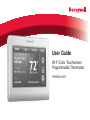
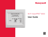
User Guide
Wi-Fi Color Touchscreen
Programmable Thermostat
RTH9580 Wi-Fi

69-2809EF—03 ii
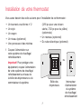
In the box you will find
• Thermostat
• Wallplate
• Screws and anchors
• Quick Start Guide
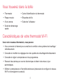
Features of your Wi-Fi thermostat
With your new thermostat, you can:
• Connect to the Internet to monitor and control your heating/cooling system.
• View and change your heating/cooling system settings.
• View and set temperature and schedules.
• Receive alerts via email and get automatic upgrades.
• View outdoor temperature and humidity (requires Wi-Fi set up and registration).
• Thermostat ID Card
• Wire labels
• User Guide

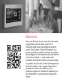
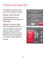
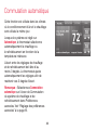
Welcome
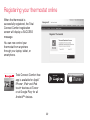
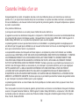
Congratulations on your purchase of a Honeywell
Wi-Fi color touchscreen programmable thermostat.
When registered to Honeywell’s Total Connect
Comfort Solutions, you can remotely monitor and
control the heating and cooling system in your home
or business—you can stay connected to your comfort
system wherever you go.
Honeywell’s Total Connect Comfort is the perfect
solution if you travel frequently, own a vacation home,
a business, or manage an investment property or if
you are simply looking for peace of mind.

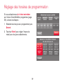
69-2809EF—03 2
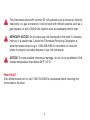
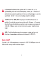
This thermostat works with common 24 volt systems such as forced air, hydronic,
heat pump, oil, gas, and electric. It will not work with millivolt systems, such as a
gas fireplace, or with 120/240 volt systems such as baseboard electric heat.
MERCURY NOTICE: Do not place your old thermostat in the trash if it contains
mercury in a sealed tube. Contact the Thermostat Recycling Corporation at
www.thermostat-recycle.org or 1-800-238-8192 for information on how and
where to properly and safely dispose of your old thermostat.
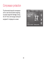
NOTICE: To avoid possible compressor damage, do not run air conditioner if the
outside temperature drops below 50°F (10°C).
Need help?
Visit wifithermostat.com or call 1-855-733-5465 for assistance before returning the
thermostat to the store.

69-2809EF—03 3
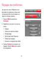
About your new thermostat
Home screen quick reference ..............4
Business screen quick reference .........5
Installation
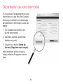
Installing your thermostat ..................... 7
Connecting to your Wi-Fi network ...... 25
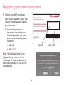
Registering your thermostat online ....30
Operation
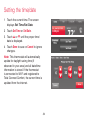
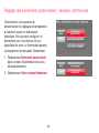
Setting the time/date ..........................34
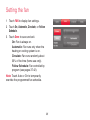
Setting the fan ....................................35
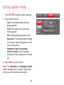
Selecting system mode ......................36
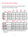
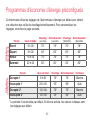
Preset energy-saving schedules ........37
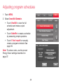
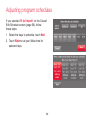
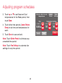
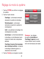
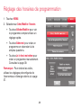
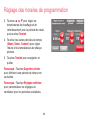
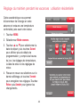
Adjusting program schedules ............. 38
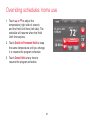
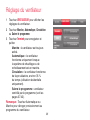
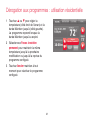
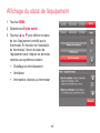
Overriding schedules–home ...............41
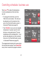
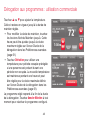
Overriding schedules–business .........42
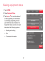
Viewing equipment status ..................43
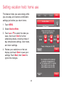
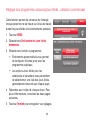
Setting vacation hold–home ...............44
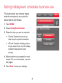
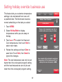
Setting holiday/event schedules–
business ..........................................45
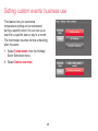
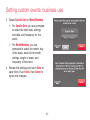
Setting custom events–business ........ 46
Setting holiday schedule–business ....48
Setting holiday override–business ......49
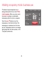
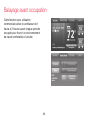
Initiating occupancy mode–business ..50
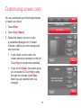
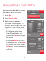
Customizing screen color ................... 51
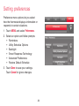
Setting preferences ............................52
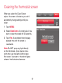
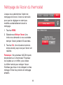
Cleaning the thermostat screen ......... 53
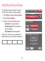
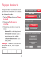
Adjusting security settings ..................54
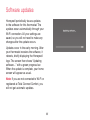
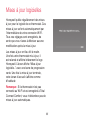
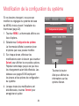
Software updates ...............................55
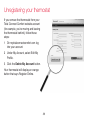
Unregistering your thermostat ............56
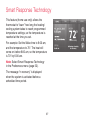
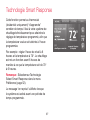
Smart Response Technology .............57
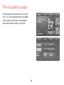
Pre-occupancy purge .........................58
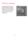
Compressor protection ....................... 59
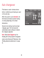
Auto changeover ................................60
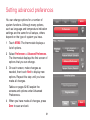
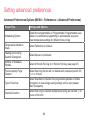
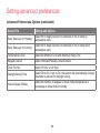
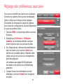
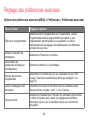
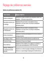
Setting advanced preferences ............61
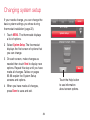
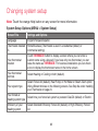
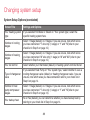
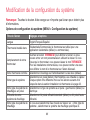
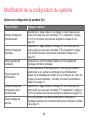
Changing system setup ......................64
Appendices
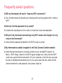
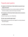
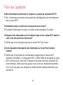
Frequently asked questions................67
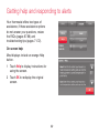
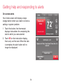
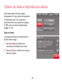
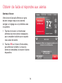
Getting help and responding to
alerts ...............................................69
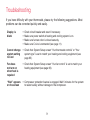
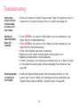
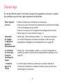
Troubleshooting ..................................71
Limited warranty .................................75
Table of contents

69-2809EF—03 4
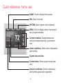
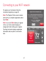
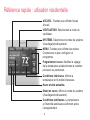
Quick reference: home use
HOME. Touch to display Home screen.
FAN. Select fan mode.
SYSTEM. Select system mode (heat/cool).
MENU. Touch to display options. Start here to
set a program schedule.
Current schedule. Change temperature
setting and select temporary or permanent
hold.
Indoor conditions. Shows indoor temperature
and humidity.
Current date and time.
Current status. Shows system mode (heat/
cool).
Outdoor conditions. Outdoor temperature
and humidity appear after registration.

5 69-2809EF—03
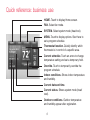
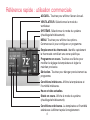
Quick reference: business use
HOME. Touch to display Home screen.
FAN. Select fan mode.
SYSTEM. Select system mode (heat/cool).
MENU. Touch to display options. Start here to
set a program schedule.
Thermostat location. Quickly identify which
thermostat is in control of a specific area.
Current schedule. Touch an arrow to change
temperature setting and set a temporary hold.
Override. Touch to temporarily override the
program schedule.
Indoor conditions. Shows indoor temperature
and humidity.
Current date and time.
Current status. Shows system mode (heat/
cool).
Outdoor conditions. Outdoor temperature
and humidity appear after registration.

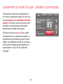
69-2809EF—03 6
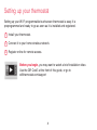
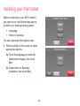
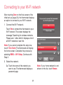
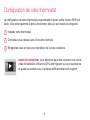
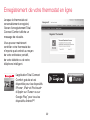
Setting up your thermostat
Setting up your Wi-Fi programmable touchscreen thermostat is easy. It is
preprogrammed and ready to go as soon as it is installed and registered.
Install your thermostat.
Connect it to your home wireless network.
Register online for remote access.
Before you begin, you may want to watch a brief installation video.
Use the QR Code
®
at the front of this guide, or go to
wifithermostat.com/support
2
3
1

7 69-2809EF—03
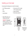
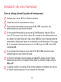
Installing your thermostat
You might need the following tools to install this thermostat:
• No. 2 Phillips screwdriver
• Pen
• Pencil
• Level (optional)
• Drill and bits (3/16” for drywall,
7/32” for plaster) (optional)
• Hammer (optional)
• Electrical tape (optional)
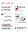
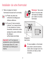
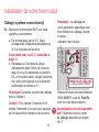
1 Switch OFF power to your
heating/cooling system.
Important! To protect your
equipment, switch OFF the power
to your heating/cooling system
at the breaker box or the system
switch.
or
M31535
Circuit
breaker
box
Heating/cooling
system power
switch

69-2809EF—03 8
C
M33823A
If you have an older thermostat
with a sealed mercury tube, turn
to page 2 for proper disposal
instructions.
Terminal
designation
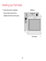
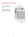
Installing your thermostat
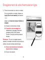
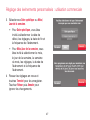
2 Remove old thermostat faceplate
and leave wires connected.
2a Take a picture of the
wire connections for later
reference.
2b If no wire is connected to
a terminal labeled C or no
C terminal exists on the
old thermostat, view the
Alternate Wiring videos at
wifithermostat.com/videos
Important! C wire is required
and is the power source for your
thermostat. Without a C wire, your
thermostat will not power up.
Note: You will need a
picture of your wire
connections to wire the
new thermostat.

9 69-2809EF—03
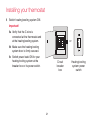
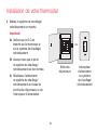
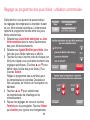
Installing your thermostat
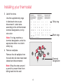
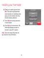
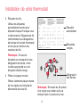
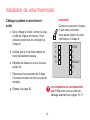
3 Label the wires.
Use the supplied sticky tags
to label each wire as you
disconnect it. Label wires
according to the old thermostat
terminal designations, not by
wire color.
Note: If no tag matches a
terminal designation, write the
appropriate letter on a blank
sticky tag.
4 Remove wallplate.
Remove the old wallplate from
the wall after all wires have been
labeled and disconnected.
Blank tags
Sticky tag
Terminal
designation
C
C
MCR31537
Note: Wrap the wires around
a pencil to prevent them from
falling back into the wall.

69-2809EF—03 10
LEVEL
HERE
R
Y
C
W
G
MCR34499
C
K
Rc
R
W-
O/B
Y
G
W2-
Aux/E
Y2
L
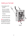
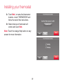
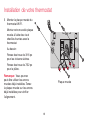
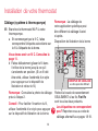
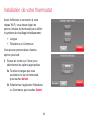
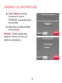
5 Mount wallplate for Wi-Fi
thermostat.
Mount your new wallplate
using screws and anchors
included with the thermostat.
If necessary:
Drill 3/16-in holes for drywall.
Drill 7/32-in holes for plaster.
Note: You may be able to use
your existing wall anchors. Hold
the wallplate up to the existing
anchors to check for alignment.
Installing your thermostat
Wallplate

11 69-2809EF—03
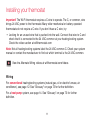
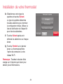
Important! The Wi-Fi thermostat requires a C wire to operate. The C, or common, wire
brings 24 VAC power to the thermostat. Many older mechanical or battery operated
thermostats do not require a C wire. If you don’t have a C wire, try:
• Looking for an unused wire that is pushed into the wall. Connect that wire to C and
check that it is connected to the 24 VAC common at your heating/cooling system.
Check the video section at wifithermostat.com
Note: Not all heating/cooling systems label the 24 VAC common C. Check your system
manual or contact the manufacturer to find out which terminal is the 24 VAC common.
View the Alternate Wiring videos at wifithermostat.com/videos
Wiring
For conventional heating/cooling systems (natural gas, oil or electric furnace, air
conditioner), see page 12. See “Glossary” on page 73 for further definition.
For a heat pump system, see page 14. See “Glossary” on page 73 for further
definition.
Installing your thermostat

69-2809EF—03 12
MCR34540
C
K
Rc
R
W-
O/B
Y
G
W2-
Aux/E
Y2
L
W
Y
G
R
C
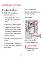
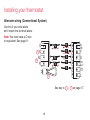
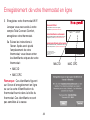
Installing your thermostat
Wiring (Conventional System)
6A Wire the Wi-Fi thermostat to your
conventional system.
a Starting with the C Wire, match the
sticky tag on the wire to the terminal
labels.
You must have a C wire. See page 11.
b
Straighten wire and gently slide
into
terminal hole until it clicks into place.
(If you need to remove a wire, use a
pen tip to press the terminal release
and then pull wire out.)
Note: Refer to the wiring picture you took
in Step 2.
Tip: To make it easier to slide the wire
into place, use a pen tip to hold down the
terminal release.
Note: The wiring for your
application might be different than
the wiring shown below.
Labels don’t match?
See alternate wiring keys
on pages 16-17.
Terminal release
Remove jumper loop ONLY if
you have both R and Rc wires.
EXAMPLE WIRING
Yours may look different

13 69-2809EF—03
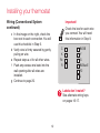
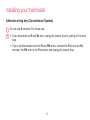
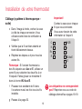
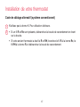
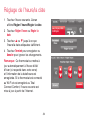
Installing your thermostat
Wiring (Conventional System
continued)
c In the image on the right, check the
box next to each connection. You will
use this checklist in Step 9.
d Verify wire is firmly secured by gently
pulling on wire.
e Repeat steps a–d for all other wires.
f Push any excess wire back into the
wall opening after all wires are
installed.
g Continue to page 20.
Labels don’t match?
See alternate wiring keys
on pages 16-17.
Important!
Check the box for each wire
you connect. You will need
this information in Step 9.
C
K
Rc
R
W-O/B
Y
G
W2-
Aux/E
Y2
L

69-2809EF—03 14
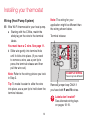
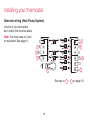
Installing your thermostat
Wiring (Heat Pump System)
6B Wire Wi-Fi thermostat to your heat pump.
a Starting with the C Wire, match the
sticky tag on the wire to the terminal
labels.
You must have a C wire. See page 11.
b Slide wire gently into terminal hole
until it clicks into place. (If you need
to remove a wire, use a pen tip to
press the terminal release and then
pull the wire out.)
Note: Refer to the wiring picture you took
in Step 2.
Tip: To make it easier to slide the wire
into place, use a pen tip to hold down the
terminal release.
Note: The wiring for your
application might be different than
the wiring shown below.
MCR34566
C
K
Rc
R
W-
O/B
Y
G
W2-
Aux/E
Y2
L
O
Y
G
R
C
AUX
Labels don’t match?
See alternate wiring keys
on pages 18-19.
Terminal release
Remove jumper loop ONLY if
you have both R and Rc wires.
EXAMPLE WIRING
Yours may look different

15 69-2809EF—03
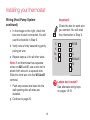
Installing your thermostat
Wiring (Heat Pump System
continued)
c In the image on the right, check the
box next to each connection. You will
use this checklist in Step 9.
d Verify wire is firmly secured by gently
pulling on wire.
e Repeat steps a–d for all other wires.
Note: If old thermostat has separate
wires on AUX and E, use a wire nut to
attach both wires to a separate wire.
Slide this third wire into the W2-Aux/E
terminal.
f Push any excess wire back into the
wall opening after all wires are
installed.
g Continue to page 20.
Labels don’t match?
See alternate wiring keys
on pages 18-19.
Important!
Check the box for each wire
you connect. You will need
this information in Step 9.
C
K
Rc
R
W-O/B
Y
G
W2-
Aux/E
Y2
L

69-2809EF—03 16
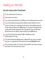
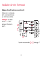
Installing your thermostat
Alternate wiring (Conventional System)
Use this if your wire labels
don’t match the terminal labels.
Note: You must have a C wire
or equivalent. See page 11.
See key to
1
–
2
on page 17.
MCR34541
C
R
W
Y
G
2
1
2
C
K
Rc
R
W-
O/B
Y
G
W2-
Aux/E
Y2
L
W1
W2
Y2
RH
4
V
Rc
R
C1
X
B

17 69-2809EF—03
Installing your thermostat
Alternate wiring key (Conventional System)
2
1
Do not use K terminal. For future use.
• IfyouhavebothanR and Rc wire, unplug the jumper loop by pulling on the wire
loop.
• IfyouroldthermostathadbothR and RH wires, connect the R wire to the Rc
terminal, the RH wire to the R terminal, and unplug the jumper loop.

69-2809EF—03 18
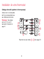
Installing your thermostat
Alternate wiring (Heat Pump System)
Use this if your wire labels
don’t match the terminal labels.
Note: You must have a C wire
or equivalent. See page 11.
See key to
1
–
7
on page 19.
MCR34542
C
R
O
Y
G
3
1
C
K
Rc
R
W-
O/B
Y
G
W2-
Aux/E
Y2
L
4
5
6
AUX
X X2
Y2
2
B
7
X
B
Rc
R
V
VR
2
L
F
W W1
W2
La page est en cours de chargement...
La page est en cours de chargement...
La page est en cours de chargement...
La page est en cours de chargement...
La page est en cours de chargement...
La page est en cours de chargement...
La page est en cours de chargement...
La page est en cours de chargement...
La page est en cours de chargement...
La page est en cours de chargement...
La page est en cours de chargement...
La page est en cours de chargement...
La page est en cours de chargement...
La page est en cours de chargement...
La page est en cours de chargement...
La page est en cours de chargement...
La page est en cours de chargement...
La page est en cours de chargement...
La page est en cours de chargement...
La page est en cours de chargement...
La page est en cours de chargement...
La page est en cours de chargement...
La page est en cours de chargement...
La page est en cours de chargement...
La page est en cours de chargement...
La page est en cours de chargement...
La page est en cours de chargement...
La page est en cours de chargement...
La page est en cours de chargement...
La page est en cours de chargement...
La page est en cours de chargement...
La page est en cours de chargement...
La page est en cours de chargement...
La page est en cours de chargement...
La page est en cours de chargement...
La page est en cours de chargement...
La page est en cours de chargement...
La page est en cours de chargement...
La page est en cours de chargement...
La page est en cours de chargement...
La page est en cours de chargement...
La page est en cours de chargement...
La page est en cours de chargement...
La page est en cours de chargement...
La page est en cours de chargement...
La page est en cours de chargement...
La page est en cours de chargement...
La page est en cours de chargement...
La page est en cours de chargement...
La page est en cours de chargement...
La page est en cours de chargement...
La page est en cours de chargement...
La page est en cours de chargement...
La page est en cours de chargement...
La page est en cours de chargement...
La page est en cours de chargement...
La page est en cours de chargement...
La page est en cours de chargement...
La page est en cours de chargement...
La page est en cours de chargement...
La page est en cours de chargement...
La page est en cours de chargement...
La page est en cours de chargement...
La page est en cours de chargement...
La page est en cours de chargement...
La page est en cours de chargement...
La page est en cours de chargement...
La page est en cours de chargement...
La page est en cours de chargement...
La page est en cours de chargement...
La page est en cours de chargement...
La page est en cours de chargement...
La page est en cours de chargement...
La page est en cours de chargement...
La page est en cours de chargement...
La page est en cours de chargement...
La page est en cours de chargement...
La page est en cours de chargement...
La page est en cours de chargement...
La page est en cours de chargement...
La page est en cours de chargement...
La page est en cours de chargement...
La page est en cours de chargement...
La page est en cours de chargement...
La page est en cours de chargement...
La page est en cours de chargement...
La page est en cours de chargement...
La page est en cours de chargement...
La page est en cours de chargement...
La page est en cours de chargement...
La page est en cours de chargement...
La page est en cours de chargement...
La page est en cours de chargement...
La page est en cours de chargement...
La page est en cours de chargement...
La page est en cours de chargement...
La page est en cours de chargement...
La page est en cours de chargement...
La page est en cours de chargement...
La page est en cours de chargement...
La page est en cours de chargement...
La page est en cours de chargement...
La page est en cours de chargement...
La page est en cours de chargement...
La page est en cours de chargement...
La page est en cours de chargement...
La page est en cours de chargement...
La page est en cours de chargement...
La page est en cours de chargement...
La page est en cours de chargement...
La page est en cours de chargement...
La page est en cours de chargement...
La page est en cours de chargement...
La page est en cours de chargement...
La page est en cours de chargement...
La page est en cours de chargement...
La page est en cours de chargement...
La page est en cours de chargement...
La page est en cours de chargement...
La page est en cours de chargement...
La page est en cours de chargement...
La page est en cours de chargement...
La page est en cours de chargement...
La page est en cours de chargement...
La page est en cours de chargement...
La page est en cours de chargement...
La page est en cours de chargement...
La page est en cours de chargement...
La page est en cours de chargement...
La page est en cours de chargement...
La page est en cours de chargement...
La page est en cours de chargement...
La page est en cours de chargement...
La page est en cours de chargement...
La page est en cours de chargement...
La page est en cours de chargement...
La page est en cours de chargement...
La page est en cours de chargement...
La page est en cours de chargement...
La page est en cours de chargement...
-
 1
1
-
 2
2
-
 3
3
-
 4
4
-
 5
5
-
 6
6
-
 7
7
-
 8
8
-
 9
9
-
 10
10
-
 11
11
-
 12
12
-
 13
13
-
 14
14
-
 15
15
-
 16
16
-
 17
17
-
 18
18
-
 19
19
-
 20
20
-
 21
21
-
 22
22
-
 23
23
-
 24
24
-
 25
25
-
 26
26
-
 27
27
-
 28
28
-
 29
29
-
 30
30
-
 31
31
-
 32
32
-
 33
33
-
 34
34
-
 35
35
-
 36
36
-
 37
37
-
 38
38
-
 39
39
-
 40
40
-
 41
41
-
 42
42
-
 43
43
-
 44
44
-
 45
45
-
 46
46
-
 47
47
-
 48
48
-
 49
49
-
 50
50
-
 51
51
-
 52
52
-
 53
53
-
 54
54
-
 55
55
-
 56
56
-
 57
57
-
 58
58
-
 59
59
-
 60
60
-
 61
61
-
 62
62
-
 63
63
-
 64
64
-
 65
65
-
 66
66
-
 67
67
-
 68
68
-
 69
69
-
 70
70
-
 71
71
-
 72
72
-
 73
73
-
 74
74
-
 75
75
-
 76
76
-
 77
77
-
 78
78
-
 79
79
-
 80
80
-
 81
81
-
 82
82
-
 83
83
-
 84
84
-
 85
85
-
 86
86
-
 87
87
-
 88
88
-
 89
89
-
 90
90
-
 91
91
-
 92
92
-
 93
93
-
 94
94
-
 95
95
-
 96
96
-
 97
97
-
 98
98
-
 99
99
-
 100
100
-
 101
101
-
 102
102
-
 103
103
-
 104
104
-
 105
105
-
 106
106
-
 107
107
-
 108
108
-
 109
109
-
 110
110
-
 111
111
-
 112
112
-
 113
113
-
 114
114
-
 115
115
-
 116
116
-
 117
117
-
 118
118
-
 119
119
-
 120
120
-
 121
121
-
 122
122
-
 123
123
-
 124
124
-
 125
125
-
 126
126
-
 127
127
-
 128
128
-
 129
129
-
 130
130
-
 131
131
-
 132
132
-
 133
133
-
 134
134
-
 135
135
-
 136
136
-
 137
137
-
 138
138
-
 139
139
-
 140
140
-
 141
141
-
 142
142
-
 143
143
-
 144
144
-
 145
145
-
 146
146
-
 147
147
-
 148
148
-
 149
149
-
 150
150
-
 151
151
-
 152
152
-
 153
153
-
 154
154
-
 155
155
-
 156
156
-
 157
157
-
 158
158
-
 159
159
-
 160
160


Honeywell RTH9580 Wi-Fi Manuel utilisateur
- Catégorie
- Thermostats
- Taper
- Manuel utilisateur
- Ce manuel convient également à
dans d''autres langues
- English: Honeywell RTH9580 Wi-Fi User manual
Documents connexes
-
Honeywell RTH8500 Manuel utilisateur
-
Honeywell RTH6580WF Manuel utilisateur
-
-
Honeywell T6 Pro Z-Wave Thermostat Le manuel du propriétaire
-
-
-
-
-
Honeywell VisionPRO Series Manuel utilisateur
-
Honeywell TH8321R1001 Le manuel du propriétaire
Autres documents
-
Honeywell Home FocusPRO Manuel utilisateur
-
 Honeywell Home TH8321WF1001 Le manuel du propriétaire
-
 Honeywell Home TH6320ZW2003/U Mode d'emploi
-
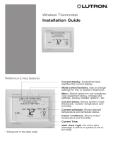 Lutron Electronics 33-00155EFS Guide d'installation
-
 Honeywell Home YTHX9421R5101WW/U Mode d'emploi
-
resideo SMHOM9585WLD3KIT Guide de démarrage rapide
-
-
GE RAK190V Le manuel du propriétaire
-
LG PREMTB10U Mode d'emploi
-
Carrier TC-WHS01 Le manuel du propriétaire


