Blue Ember BE65078-587 Mode d'emploi
- Catégorie
- Barbecues
- Taper
- Mode d'emploi
Ce manuel convient également à


22
www.blueembergrills.com
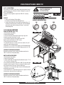
Thank you for
purchasing this barbeque
We are dedicated to creating the ultimate barbeque experience by providing you with all the right tools, starting with this manual. It is
important to read through the entire booklet prior to using your barbeque to ensure you fully understand all of the features and how to
operate your barbeque for optimum performance.
Please retain this manual for the lifetime of your barbeque after recording the serial and model number in the appropriate space allocated
below.
• The serial number can be found on the silver rating plate located on rear of the bottom pan or the back panel.
• The full model number can be found on the white label of your barbeque box or above the serial number on the silver rating plate.
WARRANTY INFORMATION
Full Model No. from outer carton:
Date Purchased:
Serial Number (from rating plate):
manual for easy reference.
Keep your receipt as proof of purchase to validate the warranty. Attach your receipt to the inside cover of this

6.0 Trouble Shooting Guide..............................................29
7.0 Warranty .................................................................30


66
www.blueembergrills.com
2.0
2.0
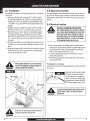
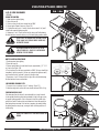
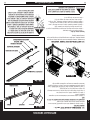
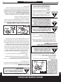
2.4.1 L.P. Gas Cylinder
Gas cylinders manufactured today have mechanisms to provide worry free
barbequing year round:
Q.C.C.1 or Type 1-Quick Connect Coupling Valve, ensure fast tank hook-ups requir-
ing only hand tightening. The redundant valve system inhibits the flow of gas to
the burner if the connection is not 100% correct.
O.P.D. or Overfill Protection Device prevents accidental gas leaks caused by
cylinder “over pressurization”, the leading cause of cylinder gas leaks. The float
in the tank will automatically stop filling at 80% capacity, leaving a 20% area for
the expansion of liquid. Without this safety feature, the relief valve may open and
discharge propane, creating a potential safety hazard. An O.P.D. cylinder is easily
distinguished by its triangular hand wheel valve. Figure 4)
Look for the Gas Guardian symbol to easily
identify propane cylinders with these safety
features.
1. SPECIFICATIONS
Self-contained propane gas barbeque systems are designed to be used only with a
9.1 kg (20 lb) propane cylinder, equipped with a Type 1 cylinder valve and incor-
porating an overfill protection device (O.P.D). This barbeque cannot be connected
to an existing #510 P.O.L. type valve (ones with left-hand threads). The cylinder
for your gas barbeque must be constructed and marked in accordance with the
specifications of L.P. gas cylinders:
In Canada: The National Standards of Canada CAN/CSA-B339, Cylinders, Spheres
and Tubes for Transportation of Dangerous Goods; and Commission.
In the U.S.: U.S. Department of Transportation (D.O.T.)
DO NOT CONNECT TO A PROPANE GAS CYLINDER EXCEEDING THIS CAPACITY,
OR USE A CYLINDER WITH ANY OTHER TYPE OF VALVE CONNECTION DEVICE.
The Type 1 valve is recognizable by the large external thread on the outlet part
of the valve. Standard existing valves do not have these exterior threads. Any
attempt to connect a regulator, with other than the:
i) Mating Type 1 connector (recognized by the large black coupling nut)
or
ii) Standard #510 P.O.L. fitting,
by use of adapters or any other means, could result in damage, fire or injury and
may negate the important safety features designed into the Type 1 system. The
connection of a #510 P.O.L. fitting will not provide the flow control or temperature
shut-off features built into the complete Type 1 system.
We strongly recommend use of a propane cylinder with Q.C.C.I and O.P.D.
safety features.
THE CYLINDER MUST ALSO BE EQUIPPED WITH:
a. A shut-off valve terminating in a proper cylinder valve outlet specified in
current standards:
b. A listed overfilling protection device (O.P.D.).
c. A safety relief valve having direct communication with the vapor space of the
cylinder.
d. A collar to protect the tank shut off valve.
e. An arrangement for vapor withdrawal.
f. A bottom ring for securing to tank support assembly.
THE CYLINDER SHOULD NOT EXCEED 472 MM (18 1/2”) IN HEIGHT AND 317
MM (12 1/2”) IN DIAMETER.
SAFETY:
sources.
back-check. A damaged back-check can be the source of a leak. Leaking
LP-GAS may cause a fire or explosion if ignited causing serious bodily injury
or death.
injury may occur.
Only install the type of dust cap on the cylinder outlet that is provided with
the cylinder valve. Other types of caps or plugs may result in leakage of
propane. (figure 6)
WARNING
!
IF THE ABOVE INSTRUCTIONS ARE NOT FOLLOWED
EXACTLY, A FIRE CAUSING DEATH OR SERIOUS INJURY
MAY OCCUR.
TM
FIG 4
FILLING STOPS
AT 80%
FLOAT
ODP
NEW OPD HANDWHEEL
CARING FOR YOUR EQUIPMENT

77
www.blueembergrills.com
2.0
2.0
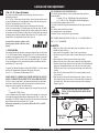
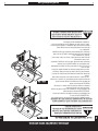
2.4.2 TRANSPORTATION AND STORAGE:
PROPANE GAS IS HEAVIER THAN AIR, AND WILL COLLECT IN LOW AREAS,
INCREASING THE ABOVE RISKS. THEREFORE:
• ALWAYS use the cylinder cap provided with your cylinder whenever the
cylinder is not connected to your barbeque. (Figure 6)
• DO NOT store in a building, garage or any other enclosed area. Store in a
well-ventilated area.
• DO NOT store near any gas burning apparatus or in any high-heat areas
such as a closed car or trunk.
side.
• DO NOT smoke while transporting a cylinder in your vehicle.
• Never ll a cylinder beyond 80% full : a re causing death
or serious injury may occur
• An over lled or improperly stored cylinder is a hazard due
to possible gas release from the safety relief valve. This
could cause an intense re with risk of property damage,
serious injury or death.
• If you see, smell or hear gas escaping, immediately get away
from the LP cylinder/appliance and call your re department.
• Never store a spare LP cylinder under or near the appliance
or in an enclosed area.
• Do not store a spare LP cylinder under or near a barbecue
grill, or other heat sources, (Figure 5a & 5b)
• Do not move the BBQ/grill when operating or while BBQ/
grill is hot.
• Never store or transport the LP cylinder where temperatures
can reach 125 F.
• Do not leave an LP cylinder in a car on a hot day.
• Do not use a damaged LP cylinder. Dented or rusty LP cylin-
ders or LP cylinders with a damaged valve may be hazard-
ous and should be replaced with a new one immediately.
WARNING
!
ALTHOUGH IT IS SAFE WHEN USED PROPERLY, CARELESS
HANDLING OF THE PROPANE GAS CYLINDER COULD
RESULT IN FIRE, EXPLOSION, AND/OR SERIOUS INJURY.
WARNING
!
IF THE INFORMATION ABOVE IS NOT FOLLOWED
EXACTLY, A FIRE CAUSING DEATH OR SERIOUS INJURY
MAY OCCUR.
FIG 5a
FIG 5b
CARING FOR YOUR EQUIPMENT

88
www.blueembergrills.com
2.0
2.0
2.4.3 FILLING:
FOR SAFETY REASONS, IF AN
OPTIONAL L.P. GAS CYLINDER
WAS SUPPLIED WITH YOUR
BARBEQUE, IT HAS BEEN
SHIPPED EMPTY. THE CYLINDER
MUST BE PURGED OF AIR AND
FILLED PRIOR TO USING ON
YOUR BARBEQUE. WHEN GET-
TING YOUR CYLINDER FILLED:
injury may occur.
2.4.4 LP Cylinder exchange
Many retailers that sell grills offer you the option of replacing your empty LP cylin-
der through an exchange service. Use only those reputable exchange companies
that inspect, precision fill, test and certify their cylinders. Exchange your cylinder
only for an OPD safety feature-equipped cylinder as described in the “LP Cylinder”
section of this manual.
transit or storage.
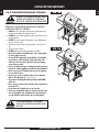
2.5 Hose & Regulator
PROPANE GAS MODELS:
Your barbeque is designed to operate on L.P. (propane) gas at a pressure
regulated at 2.74 kPa (11” water column). A regulator preset to this pressure is
supplied with the barbeque and MUST be used.
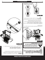
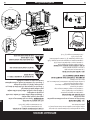
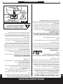
This regulator is equipped with the Q.C.C. Type 1, quick connect coupling system,
which incorporates the following safety features: (Figure 7)
150°C (240 and 300°F)
of gas to 0.28 cubic metres per hour (10 cubic feet per hour)
Prior to attaching the propane cylinder to the hose and regulator, be sure the
cylinder valve and the appliance valves are OFF. The cylinder valve is turned off by
rotating the handwheel (see Figure 4) clockwise (left to right) until it stops and
all appliance valves should be in the twelve o’clock position. When attaching the
regulator to the cylinder, make sure that the small probe in the nipple is centered
in the mating Q.C.C. 1 cylinder valve (see Figure 7). Turn the right hand threaded
Q.C.C.1 black nut onto the valve in a clockwise motion until there is a positive
stop.
DO NOT USE A WRENCH, HAND TIGHTEN ONLY.
Should the large black thermally sensitive coupling nut be exposed to tempera-
tures above 115 - 150°C, it will soften and allow the regulator probe to disen-
gage from the cylinder valve – thereby shutting off the flow of gas. Should this
occur, do not attempt to reconnect the nut. Remove the entire regulator assembly,
and replace it with a new one.
The cause of the excessive heat should be determined and cor-
rected before operating your barbeque again. The regulator probe also contains
a flow-sensing element, which will limit the flow of gas to the regulator to a
manageable amount (0.28 cubic metres/hour) in the event of a hose or regulator
rupture. If it is evident that the flow control device has been activated, the cause
of the excessive flow should be determined and corrected before using your
barbeque again.
WARNING
!
WARNING: INDICATES AN POTENTIALLY HAZARDOUS
SITUATION WHICH, IF NOT AVOIDED, COULD RESULT IN
DEATH OR SERIOUS INJURY.
FIG 7
REGULATOR
REGULATOR
STRAIGHT
Q.C.C.I
Q.C.C.I
DANGER
!
DO NOT INSERT ANY TOOL OR FOREIGN OBJECT INTO
THE VALVE OUTLET OR SAFETY RELIEF VALVE. YOU MAY
DAMAGE THE VALVE AND CAUSE A LEAK. LEAKING
LP-GAS MAY CAUSE A FIRE OR EXPLOSION IF IGNITED
CAUSING SERIOUS BODILY INJURY OR DEATH.
WARNING
WARNING
!
!
NEVER OPERATE GRILL WITH LP CYLINDER OUT OF COR-
RECT POSITION SPECIFIED IN ASSEMBLY INSTRUCTIONS.
CONTAINED LP GAS SYSTEM OF A CAMPER TRAILER
OR MOTOR HOME.
THE FIRE DEPARTMENT.
CLOSE LPCYLINDER VALVE AND CALL LP GAS SUP-
PLIER OR YOUR FIRE DEPARTMENT!
WARNING
!
ALWAYS CLOSE LP CYLINDER VALVE AND REMOVE
COUPLING NUT BEFORE MOVING LP CYLINDER FROM
SPECIFIED OPERATION POSITION.
FIG 6
RETAINER
STRAP
LP TANK
VALVE
CYLINDER
CAP
CARING FOR YOUR EQUIPMENT

99
www.blueembergrills.com
2.5 Hose & Regulator continued
NOTE: IMPROPER LIGHTING PROCEDURES CAN CAUSE THE FLOW CONTROL
TO ACTIVATE, RESULTING IN REDUCED HEAT OUTPUT. IF THIS IS SUSPECTED,
RESET THE FLOW CONTROL BY SHUTTING OFF ALL BURNER CONTROLS AND
THE CYLINDER VALVE. WAIT 30 SECONDS, THEN TURN THE CYLINDER VALVE
ON EXTREMELY SLOWLY - WAIT 5 SECONDS AND TURN THE BURNER VALVE
ON AND LIGHT AS NORMAL.
supply or any other gas. Do not attempt to alter the hose or regulator in any
way.
-
pane tank. If the fitting is allowed to drag on the ground, nicks and scratches
could occur resulting in a leak when connected to the propane tank.
operation.
PROPANE AND NATURAL GAS MODELS:
gas appliance is not in use.
allow the hose to come in contact with any hot surfaces of the barbeque.
of the barbeque. If it is evident there is excessive abrasion/wear, or the
hose is cut, it must be replaced prior to using your barbeque. Only the hose
assembly as specified in the Parts List should be used.
first time, every time a propane cylinder is refilled, if any gas component
is changed, if the regulator flow-limiting device has been activated, after
prolonged periods of storage or non-use or at least once per season.
LIQUID PROPANE GAS UNITS ONLY:
barbecue.
gas fitting while your barbecue is in operation.
checked by your liquid propane supplier. Do not use a liquid propane cylinder
with a damaged valve.
be present, and the cylinder should be transported and stored accordingly.
cylinder:
1. Move away from liquid propane cylinder.
2. Do not attempt to correct the problem yourself.
3. Call your fire department.
NATURAL GAS MODELS:
gas supply piping during any pressure testing of the system at test pressure
in excess of 3.5 kPa (1/2 p.s.i.).
its individual manual shut-off valve during any pressure testing of the gas
supply piping system at pressures equal to or less than 3.5 kPa (1/2 p.s.i.).
of 3.6 m (12 ft). Always disconnect hose at quick connect coupling when
storing your barbeque.
in use.
WARNING
WARNING
!
!
FAILURE TO ENSURE THE ABOVE MAY RESULT IN A
HAZARDOUS FIRE OR EXPLOSION CAUSING SERIOUS
BODILY INJURY AND/OR PROPERTY DAMAGE.
DO NOT ATTEMPT TO REPAIR OR ALTER THE HOSE/
VALVE/REGULATOR FOR ANY “ASSUMED” DEFECT. ANY
MODIFICATION TO THIS ASSEMBLY WILL VOID YOUR
WARRANTY AND CREATE THE RISK OF A GAS LEAK AND
FIRE. USE ONLY AUTHORIZED REPLACEMENT PARTS
SUPPLIED BY MANUFACTURER.
CARING FOR YOUR EQUIPMENT
2.0
2.0

1010
www.blueembergrills.com
3.0
3.0
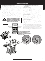
Cleaning & Maintenance
To keep your barbeque working at its peak efficiency as well as contribute to the
safe operation of this unit, perform all of the operations below at least once a year
- preferably at the start of each cooking season.
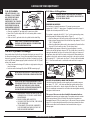
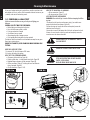
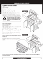
3.1 PERFORM A LEAK TEST
A leak test ensures that there are no gas leaks prior to lighting your
barbeque.
WHEN A LEAK TEST MUST BE PERFORMED:
The leak test should be performed in a well-ventilated area away from any open
flame, heat or ignition sources.
DO NOT USE A MATCH, OPEN FLAME OR SMOKE DURING LEAK
TESTING.
WHAT YOU’LL NEED FOR TESTING:
1. A mixture of 50% liquid dish soap and 50% water.
2. A brush or cloth to apply the mixture.
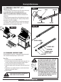
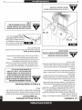
AREAS TO TEST ON A PROPANE BARBEQUE:
tubing,if equipped (Figure 8D)
AREAS TO TEST ON NATURAL GAS BARBEQUES:
ACCESSING THE VALVES AND MANIFOLD:
WARNING: Ensure that all gas is turned off before attempting the follow-
ing steps.
1-disconnect the side burner hose and sonarque wiring if your model comes
equipped with either of these features (Figure 8D)
2-remove the wing nuts from the side shelves and completely remove the
sideshelves from the bbq/grill
3-loosen the set screws on the bottom side of the knobs and remove the knobs.
4-Loosen x4 screws from the side of the console and completely remove the
console to access the valves and manifold.
A
B
DETAIL A
DETAIL B
FIG 8a
FIG 8b
FIG 8c
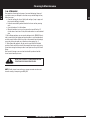
WARNING
!
IF THE ABOVE INSTRUCTIONS ARE NOT FOLLOWED
EXACTLY, A FIRE CAUSING
DEATH OR SERIOUS INJURY MAY OCCUR.
WARNING
!
DO NOT OPERATE THE GAS BARBECUE IF THERE IS A
GAS LEAK PRESENT.
WARNING
!
DO NOT USE A FLAME TO CHECK FOR GAS LEAKS.

1111
www.blueembergrills.com
3.0
3.0
Cleaning & Maintenance
3.1 PERFORM A LEAK TEST con’t...
HOW TO DO THE TESTING:
on your propane cylinder 1 turn, or the main natural gas valve on.
DO NOT IGNITE THE BURNERS WHILE PERFORMING THE LEAK CHECK.
2. Brush your soap and water solution on all connections and components as
outlined above.
3. Observe each place for growing bubbles, which indicate that a leak is present.
4. Shut off the flow of gas while fixing the leak. Tighten any leaking connection
and repeat test until no leaks are detected.
5. If the leak(s) cannot be stopped DO NOT USE. Shut off the fuel source at the
valve immediately (if appropriate, remove propane cylinder). Call a certified gas
appliance service person, or a gas dealer for proper repairs.
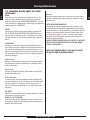
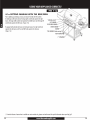
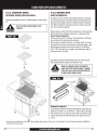
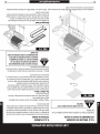
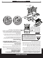
3.2 CLEANING VENTURI TUBES
Periodic cleaning of the venturi tubes is recommended for optimum burner perfor-
mance, especially after prolonged storage or a period of non-use.
How to Clean:
at a time, then remove to prevent moving the debris upwards (Figure 9).
debris.
seated over the valve orifices (Figure 1).
WARNING
!
IT IS POSSIBLE THAT VERY SMALL INSECTS COULD MAKE
WEBS OR NEST IN THE VENTURI TUBES, AS THEY ARE
NATURALLY ATTRACTED TO THE SMELL OF GAS. THIS
WILL PARTIALLY OR COMPLETELY BLOCK THE FLOW OF
GAS THROUGH THE VENTURI AND IS INDICATED BY A
SMOKY YELLOW FLAME, AND/OR A BURNER THAT IS
DIFFICULT OR IMPOSSIBLE TO LIGHT. ULTIMATELY, IT
MAY CAUSE THE GAS TO BURN OUTSIDE THE VENTURIS,
WHICH CAN CAUSE A FIRE RESULTING IN DAMAGE TO
YOUR BARBEQUE AND POTENTIAL PERSONAL INJURY.
IF THIS HAPPENS IMMEDIATELY SHUT OFF THE PROPANE
AT CYLINDER. WHEN THE BARBEQUE HAS COOLED, FOL-
LOW THE “HOW TO CLEAN” STEPS ABOVE.
FIG 9
BLOCKAGE
VENTURI
VALVE
CLEANING BRUSH
FIG 9a
IGNITOR ASSEMBLY
BURNER PORTS
TUBE BURNER
BURNER VENTURI
VENTURI SCREEN
AIR SLEEVE
WARNING
!
DO NOT ENLARGE VALVE ORIFICES OR BURNER PORTS
WHEN CLEANING THE VALVES OR BURNERS.
FIG 8d

1212
www.blueembergrills.com
3.0
3.0
Cleaning & Maintenance
3.3 CLEANING OTHER PARTS OF YOUR
APPLIANCE
BURNER:
At least twice a year, clean your burner when cleaning the venturi tubes. The
burner can be gently scraped clean with a brass bristle brush. Ensure that all
burner ports (openings) are clear (DO NOT ENLARGE BURNER PORTS). If you find
cracks, abnormal holes, or damage caused by corrosion during your inspection and
cleaning, replace burner. (SEE WARRANTY).
IGNITOR:
Clean the ignitor clip lightly using a wire brush to remove rust and grease. DO
NOT USE WATER OR CLEAN THE ELECTRODE WITH THE WIRE BRUSH. Visually
inspect the ceramic of the electrode for cracks. The electrode can be wiped with
a soft cloth if necessary. If a crack is found, a replacement ignitor system will be
required.
CLEANING GRIDS:
After each use, scrub the cooking grids with a stiff long-handled brass brush. Do
not use steel brushes, as they can scratch the nickel or porcelain coating. Grids can
also be washed with mild detergent. Never use commercial oven cleaners. If rust
appears on your cooking grids, remove the rust with a scrub pad and coat the grid
with some cooking oil. If excessive wear is evident, you might want to replace or
upgrade your cooking grid.
Porcelain surfaces:
Because of glass-like composition, most residue can be wiped away with baking
soda/water solution or specially formulated cleaner. Use nonabrasive scouring
powder for stubborn stains.
Painted surfaces:
Wash with mild detergent or nonabrasive cleaner and warm soapy water. Wipe
dry with a soft nonabrasive cloth.
Stainless steel surfaces:
To maintain your grill’s high quality appearance, wash with mild detergent and
warm soapy water and wipe dry with a soft cloth after each use. Baked-on grease
deposits may require the use of an abrasive plastic cleaning pad. Use only in
direction of brushed finish to avoid damage. Do not use abrasive pad on areas
with graphics.
SIDE SHELVES:
Metal Shelves: Use any household cleaner, except those containing acid or mineral
spirits. Be sure to rinse well after cleaning.
DO NOT USE AS A CUTTING BOARD.
Plastic Shelves: Wash with warm soapy water and wipe dry. Do not use citrisol,
abrasive cleaners, degreasers or a concentrated grill cleaner on plastic parts. Dam-
age to and failure of parts can result.
Plastic parts:
Wash with warm soapy water and wipe dry. Do not use citrisol, abrasive cleaners,
degreasers or a concentrated grill cleaner on plastic parts. Damage to and failure
of parts can result.
CASTING INTERIOR AND WARMING RACK:
At least once a year remove all components from inside your barbeque. Loosen
any cooking residue with a scraping tool for large particles and a brass barbeque
brush for smaller particles. Scrub with hot water and a strong detergent, then rinse
thoroughly or spray barbeque degreaser liberally on all interior surfaces. Be sure
to use gloves and eye protection. Let stand for 10 minutes, scrape off residue
and repeat if required. Rinse thoroughly with water. Replace all components as
outlined in the assembly instructions.
DO NOT USE DEGREASER ON PAINTED OR PLASTIC SURFACES. DO NOT ALLOW
EXCESSIVE GREASE OR OTHER RESIDUE TO BUILD UP ON YOUR COOKING
SYSTEM AS A FIRE MAY RESULT.
COVER YOUR BARBEQUE WHEN IT IS NOT IN USE TO PROTECT
THE SHELVES FROM THE OUTDOOR ELEMENTS

1313
www.blueembergrills.com
3.0
3.0
Cleaning & Maintenance
3.4 CLEANING GREASE PAN
General Grill Cleaning: Do not mistake brown or black accumulation of grease and
smoke for paint. Interiors of gas grills are not painted at the factory (and should
never be painted). Apply a strong solution of detergent and water or use a grill
cleaner with scrub brush on insides of grill lid and bottom. Rinse and allow to
completely air dry. Do not apply a caustic grill/oven cleaner to painted surfaces.
Grease PAN and Grease Tray Insert: The grease tray and insert are lo-
cated on the bottom of the base casting, below the grease pan, and immediately
below the hole through which any grease will drain. The grease pan tray insert
should be checked and replaced and cleaned prior to each use to prevent grease
from overflowing.
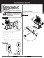
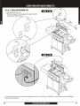
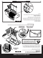
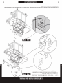
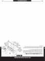
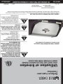
3.5 PROPER INSTALLATION OF THE
GREASE PAN
SECURING THE GREASE PAN
1-Look at the back of your grill. With the original grease pan removed, you should
become familiar with the rail and locking system.
2-The base casting of the BBQ/Grill firebox has an integrated rail design that
secures and holds the grease pan in place. The base casting has unique tabs that
lock and secure the grease pan in place.
3-install the grease pan by sliding it into place, using the rails as a guide.
CORRECT INSTALLATION
4-Push the grease pan forward as far as possible. When properly installed, the
edge of the grease pan should not extend beyond the end of the base casting
grease pan rails at the back of the BBQ/grill box. The tabs of the grease pan/
heat shield will lock in place, securing it.
INCORRECT INSTALLATION
5-If the grease pan is not fully inserted and locked in place, the edge of the grease
pan will extend beyond the end of the base casting grease pan rails at the back of
the BBQ/grill box.
THIS BBQ/GRILL MUST BE OPERATED WITH A GREASE PAN INSTALLED AT ALL
TIMES. ALWAYS ENSURE THAT THE GREASE PAN IS FULLY INSERTED. THE GREASE
PAN SHOULD BE CHECKED AND CLEANED PRIOR TO EACH USE TO PREVENT
GREASE BUILDUP AND OVERFLOW. FAILURE TO DO SO MAY RESULT IN A GREASE
FIRE. MAKE SURE THE BBQ/GRILL IS COOL BEFOREREMOVING THE GREASE PAN.
WARNING
!
ENSURE THAT GREASE PAN AND TRAY ARE EMPTIED
AFTER EACH USE. IF EXCESS GREASE IS ALLOWED TO
ACCUMULATE, A POSSIBLE FIRE CAUSING PROPERTY
DAMAGE OR SERIOUS INJURY MAY OCCUR.
FIG 10
A
B
NOTE: NOTE THE PROPER ORIENTATION OF GREASE
PAN AS SHOWN. ALIGN THE DRIP HOLE OF THE
GREASE PAN DIRECTLY OVER TOP OF THE CLEARANCE
HOLE IN THE HEAT SHIELD.
BACK VIEW
BACK TIP VIEW
✔
✗

1414
www.blueembergrills.com
3.0
3.0
Cleaning & Maintenance
3.6 STORAGE
More people are discovering the pleasure of year round barbequing. However, if
you choose to store your barbeque for the winter or any extended length of time,
follow these steps:
then store the cooking grids indoors.
racks.
cylinder valve or main shut off valve, and stored outdoors in a well-ventilated
area.
1. With a Propane appliance you can store the barbeque inside, PROVIDED the cyl-
inder is removed from the barbeque and stored outdoors in a well-ventilated area,
out of the reach of children. When the cylinder is disconnected from the barbeque,
ensure the cylinder valve safety cap is placed over valve opening (fig. 6).
2. With a Natural Gas appliance, the gas must be turned off at the individual
gas shut off valve and the hose must be disconnected from the gas supply piping
system before storing the barbeque indoors. Install plastic covers to quick connect
fittings.
After a period of storage or non-use a leak test should be performed and the
burner venturis cleaned prior to use.
NOTE: Visually inspect burners and ensure a proper connection to valves each
time after moving or transporting your BBQ/Grill.
WARNING
!
NEVER STORE A SPARE LP CYLINDER UNDER OR NEAR
THE APPLIANCE OR IN AN ENCLOSED AREA.


1616
www.blueembergrills.com
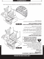
NOTE: Tank sensor is only compatible with tanks constructed of steel.
Aluminum
and composite tanks are not compatible. The tank sensor must be in direct
contact with the bottom of the tank and must be clean and free of debree.
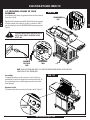
4.2 IGNITOR BATTERY
Ensure BATTERY is installed correctly, put - (negative) side of battery in first.
(Figure 13)
4.0
4.0
USING YOUR APPLIANCE CORRECTLY
4.1.1
models indicated with “s” (ex. BE569s, BE557s, BE545s)
UNDERSTANDING AND OPERATING
YOUR FUEL GAUGE ASSEMBLY WITH
TANK SENSOR
Before operating your tank sensor, ensure that all of the installation steps found in
this manual have been followed.
Ensure that the wire harness is completely installed and that the tank
sensor is clean and free of debris before using.
To POWER ON your Fuel Gauge Assembly with Tank Sensor push the button x1 as
indicated. To POWER OFF push the button x1 as indicated.
• The Fuel Gauge Assembly indicates the remaining propane fuel and cooking
time remaining based on fuel flow rate.
• LCD bars update every 30 seconds to display the actual level of propane
remaining in the tank.
• NOTE: Natural Gas units will not show fuel level or time remaining as the gas
supply will always remain at 100%.x
WARNING
!
FAILURE TO ENSURE THESE INSTRUCTIONS MAY RESULT
IN HAZARDOUS FIRE OR EXPLOSION CAUSING SERIOUS
BODILY INJURY AND/OR PROPERTY DAMAGE AND
INVALIDATES WARRANTY
Tank Sensor
Wire Harness
Push (x1) - Power ON
Push (x1) - Power OFF
FIG 12a
FIG 12b
FIG 13
B
A
DETAIL A
SCALE 1 : 2
+
–

1717
www.blueembergrills.com
A
DETAIL A
4.0
4.0
USING YOUR APPLIANCE CORRECTLY
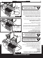
4.2.1 LIGHTING
Prior to lighting your barbeque, visually check all hoses before each use for nicks,
cracking, abrasions or cuts. If the hose is found to be damaged in any way, DO
NOT USE YOUR BARBEQUE.
Brochure).
IMPORTANT
Visually check the flames every time you light your barbeque (Figure 14).
If the flame is abnormally small or a smoky yellow - shut off the barbeque
and check the venturi tubes for blockage (see Figure 9) or refer to the
Troubleshooting Guide.
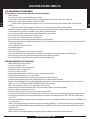
4.2.2 MAIN BURNERS
USING THE IGNITOR (Figure 11A)
1. Read instructions before lighting.
2. Open the lid before lighting.
3. Turn off all of the burner control knobs and close the gas supply valve.
4. Open the gas supply valve and wait 5 seconds.
All other control knobs should be in the “OFF” position.
6. Depress the ignitor, repeat if necessary.
7. If ignition does not occur in 5 seconds, turn the burner control(s) off, wait 5
minutes, and repeat the lighting procedure.
8. Repeat steps 1 to 6. If burner still fails to light, refer to Troubleshooting Guide
to determine cause and solution, or try the Match Lighting procedure (Fig. 14B).
LIGHTING THE OTHER MAIN BURNERS
Once one burner has been lit, push in and turn the adjacent control knob to
MATCH LIGHTING PROCEDURE
1. Read instructions before lighting.
2. Open the lid before lighting.
3. Place an ignited lighter or lit match through the lighting hole, approx. 1.25 cm
(1/2”) from burner. (See Figure 14B)
immediately (within five seconds). If it does not, extinguish the lighter or match,
turn the control knob to off, and wait 5 minutes to clear the gas.
5. Repeat steps 1 to 3. If burner fails to light, refer to the Troubleshooting Guide
to determine cause and solution.
6. Once left hand burner is lit, light remaining burners in this sequence: left burner,
left center burner, right center burner, then right burner.
LIGHTING THE OTHER MAIN BURNERS
Once one burner has been lit, push in and turn the adjacent control knob to
CAUTION
!
IF LIGHTING MAIN BURNERS ONLY,
ENSURE SIDE BURNER KNOB
IS IN THE OFF POSITION.
FIG 14
FIG 14A
FIG 14B
OFF LOW
LOW
HIGH
HIGH
A
DETAIL A
KNOB ORIENTATION
2.
3.
5.
4.
6.
2.
3.
4.

1818
www.blueembergrills.com
MAX
4.0
4.0
USING YOUR APPLIANCE CORRECTLY
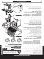
4.2.3 SIDE BURNER
(OPTIONAL)
USING THE IGNITOR
1. Read instructions before lighting.
2. Raise side burner lid.
4. Depress ignitor. Repeat if necessary (Figure 15A).
5. If ignition does not occur in 5 seconds, turn the burner control(s) off, wait 5
minutes, and repeat the lighting procedure.
6. Repeat steps 1 to 4. If burner still fails to light, refer to the Troubleshooting
Guide to determine cause and solution, or try the match lighting procedure below.
MATCH LIGHTING PROCEDURE
1. Read instructions before lighting.
2. Raise side burner lid.
3. Place an ignited lighter or lit match near the ports, approximately 1/2” (1.25
cm) from burner (Figure 15B).
immediately (within five seconds). If it does not, extinguish the lighter or match,
turn the control knob off, and wait 5 minutes for the gas to clear.
5. Repeat steps 1 and 3. If burner still fails to light, refer to the Troubleshooting
Guide to determine the cause and solution.
SIDE BURNER COOKING POTS
1. Ensure pot size is a maximum size of 9” wide only (Figure 15C).
2. Maximum weight to be used on side burner should not exceed 20 lbs (9 kg)
PROPANE MODELS ONLY
If the heat output from the burner(s) seem abnormally low, it may be caused
by the regulator flow-limiting device being activated by a leak in the gas system,
or improper lighting procedures. If this is suspected, shut off the cylinder valve
and all burner valves. Perform a leak test to determine if a leak has caused the
flow-limiting device to activate. If the leak test is negative, then carefully follow
the lighting procedures step-by-step, ensuring all valves (including tank) are off
before starting.
WARNING
!
DO NOT LIGHT SIDE BURNER WITH LID DOWN. FAILURE
TO DO SO MAY CAUSE SERIOUS BODILY INJURY AND/
OR PROPERTY DAMAGE
WARNING
CAUTION
!
!
ENSURE SIDE BURNER LID IS UP BEFORE LIGHTING SIDE
BURNER.
SIDE BURNER FLAME MAY BE DIFFICULT TO SEE ON
A BRIGHT SUNNY DAY. ALWAYS USE CAUTION WHEN
OPERATING THE SIDE BURNER.
MAX
FIG 15A
FIG 15B
FIG 15A
2.
3.
4.
3.
4.
2.


La page est en cours de chargement...
La page est en cours de chargement...
La page est en cours de chargement...
La page est en cours de chargement...
La page est en cours de chargement...
La page est en cours de chargement...
La page est en cours de chargement...
La page est en cours de chargement...
La page est en cours de chargement...
La page est en cours de chargement...
La page est en cours de chargement...
La page est en cours de chargement...
La page est en cours de chargement...
La page est en cours de chargement...
La page est en cours de chargement...
La page est en cours de chargement...
La page est en cours de chargement...
La page est en cours de chargement...
La page est en cours de chargement...
La page est en cours de chargement...
La page est en cours de chargement...
La page est en cours de chargement...
La page est en cours de chargement...
La page est en cours de chargement...
La page est en cours de chargement...
La page est en cours de chargement...
La page est en cours de chargement...
La page est en cours de chargement...
La page est en cours de chargement...
La page est en cours de chargement...
La page est en cours de chargement...
La page est en cours de chargement...
La page est en cours de chargement...
La page est en cours de chargement...
La page est en cours de chargement...
La page est en cours de chargement...
La page est en cours de chargement...
La page est en cours de chargement...
La page est en cours de chargement...
La page est en cours de chargement...
-
 1
1
-
 2
2
-
 3
3
-
 4
4
-
 5
5
-
 6
6
-
 7
7
-
 8
8
-
 9
9
-
 10
10
-
 11
11
-
 12
12
-
 13
13
-
 14
14
-
 15
15
-
 16
16
-
 17
17
-
 18
18
-
 19
19
-
 20
20
-
 21
21
-
 22
22
-
 23
23
-
 24
24
-
 25
25
-
 26
26
-
 27
27
-
 28
28
-
 29
29
-
 30
30
-
 31
31
-
 32
32
-
 33
33
-
 34
34
-
 35
35
-
 36
36
-
 37
37
-
 38
38
-
 39
39
-
 40
40
-
 41
41
-
 42
42
-
 43
43
-
 44
44
-
 45
45
-
 46
46
-
 47
47
-
 48
48
-
 49
49
-
 50
50
-
 51
51
-
 52
52
-
 53
53
-
 54
54
-
 55
55
-
 56
56
-
 57
57
-
 58
58
-
 59
59
-
 60
60


Blue Ember BE65078-587 Mode d'emploi
- Catégorie
- Barbecues
- Taper
- Mode d'emploi
- Ce manuel convient également à
dans d''autres langues
- English: Blue Ember BE65078-587 User guide
Autres documents
-
Huntington 30040HNT Manuel utilisateur
-
LANDMANN 42259 Troubleshooting guide
-
Master Chef T360 Assembly Manual
-
Patton Master fourburner Le manuel du propriétaire
-
 Wellis Cherokee Silver Quintet Manuel utilisateur
-
Twin Eagles TEPB24-CL Le manuel du propriétaire
-
-
Proline BQ 22 Instructions For Use Manual
-
Delta Heat DHBQ26G-C Mode d'emploi
-
DCS BGB48-BQRL Manuel utilisateur
