Nilfisk AS4325B-CAN DISC 17 IN Le manuel du propriétaire
- Catégorie
- Machine à plancher
- Taper
- Le manuel du propriétaire
Ce manuel convient également à

AS4325B
INSTRUCTION FOR USE
Model No.: 50000580
VS15315 Rev. A JAN. 2020
Original instructions

FCC Supplier's Declaration of Conformity
47 CFR § 2.1077 Compliance Information
Unique Identifier: FC - Floor Scrubber/Sweeper - Battery Type: AS4325
Responsible Party – U.S. Contact Information:
Nilfisk, Inc
9435 Winnetka Ave N
Brooklyn Park
Minnesota
MN-55442
USA
www.nilfisk.com
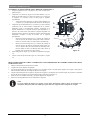
FCC Compliance Statement
This device complies with part 15 of the FCC rules. Operation is subject to the following two conditions: (1)
This device may not cause harmful interference, and (2) this device must accept any interference received,
including interference that may cause undesired operation. Users are not permitted to make changes or
modify the device in any way. Changes or modifications not expressly approved by Nilfisk, Inc. will void the
user’s authority to operate the equipment.
Brooklyn Park
Nov 22, 2019
Jamie O'Neill
Senior Vice President, USFC Sales, EMEA Americas Sales

IC Supplier's Declaration of Conformity
ICES-Gen
Unique Identifier: FC - Floor Scrubber/Sweeper - Battery Type: AS4325
Responsible Party – Contact Information:
Nilfisk Canada Company
240 Superior Boulevard
Mississauga
Ontario
L5T 2L2
Canada
www.nilfisk.com
IC Compliance Statement
This device complies with Industry Canada ICES-002. Operation is subject to the following two conditions:
(1) This device may not cause harmful interference, and (2) this device must accept any interference
received, including interference that may cause undesired operation.
Mississauga
Nov 22, 2019
Steven Surtel
General Manager

TABLE OF CONTENTS
ENGLISH
FRANÇAIS
ESPAÑOL
PARTS LIST
INSTRUCTION FOR USE……………………………………… 1-25
MANUEL UTILISATEUR……………………………………… 26-50
INSTRUCCIONES DE USO……………………………………. 51-75
……………………………………………………………………… 76-98

INSTRUCTION FOR USE ENGLISH
1
TABLE OF CONTENTS
INTRODUCTION .........................................................................................................................................2
GUIDE PURPOSE AND CONTENTS .......................................................................................................................... 2
HOW TO KEEP THIS INSTRUCTION FOR USE ....................................................................................................... 2
DECLARATION OF CONFORMITY ........................................................................................................................... 2
ACCESSORIES AND MAINTENANCE ...................................................................................................................... 2
CHANGE AND IMPROVEMENT ................................................................................................................................ 2
SCOPE OF APPLICATION ........................................................................................................................................... 2
MACHINE IDENTIFICATION DATA ......................................................................................................................... 2
TRANSPORT AND UNPACKING ............................................................................................................................... 3
SAFETY .........................................................................................................................................................3
VISIBLE SYMBOLS ON THE MACHINE .................................................................................................................. 3
SYMBOLS THAT APPEAR ON THE INSTRUCTION FOR USE .............................................................................. 3
GENERAL SAFETY INSTRUCTION .......................................................................................................................... 4
MACHINE DESCRIPTION ........................................................................................................................6
MACHINE STRUCTURE (as shown in Figure 1) ......................................................................................................... 6
CONTROL PANEL (as shown in Figure 2) ................................................................................................................... 7
DISPLAY WINDOW OF CHARGER INDICATON LIGHT (as shown in Figure 2) ................................................... 7
MACHINE SIZE ............................................................................................................................................................ 8
TECHNICAL PARAMETERS ....................................................................................................................................... 9
WIRING DIAGRAM .................................................................................................................................................... 10
OPERATING GUIDE .................................................................................................................................11
BATTERY CHECK/SETTING ON A NEW MACHINE ............................................................................................ 11
BATTERY INSTALLATION AND BATTERY TYPESETTING (WET OR GEL/ AGM) ....................................... 12
BRUSH/PAD-HOLDER INSTALLATION AND REMOVAL ................................................................................... 14
SQUEEGEE ASSEMBLE INSTALLATION AND REMOVAL ................................................................................ 15
SOLUTION OR WASHING WATER TANK FILLING ............................................................................................. 16
MACHINE START AND STOP .................................................................................................................................. 16
MACHINE OPERATION (SCRUBBING AND DRYING) ........................................................................................ 17
TANK EMPTYING ...................................................................................................................................................... 18
AFTER USING THE MACHINE ................................................................................................................................ 18
MACHINE LONG INACTIVITY ................................................................................................................................ 19
FIRST PERIOD OF USE .............................................................................................................................................. 19
MAINTENANCE ........................................................................................................................................19
SCHEDULED MAINTENANCE TABLE ................................................................................................................... 19
BATTERY CHARGING .............................................................................................................................................. 20
BRUSH/PAD CLEANING ........................................................................................................................................... 21
SOLUTION FILTER CLEANING ............................................................................................................................... 22
SQUEEGEE CLEANING ............................................................................................................................................. 22
SQUEEGEE BLADE CHECK AND REPLACEMENT .............................................................................................. 23
TANK AND VACUUM GRID WITH FLOAT CLEANING, AND COVER GASKET CHECK .............................. 23
ACCESSORIES/OPTIONS .......................................................................................................................................... 24
TROUBLESHOOTING ..............................................................................................................................25
SCRAPPING ................................................................................................................................................25

INSTRUCTION FOR USE ENGLISH
2
INTRODUCTION
NOTE
The numbers in brackets refer to the components shown in Machine Description chapter.
GUIDE PURPOSE AND CONTENTS
The purpose of this instruction for use is to provide the operator with all basic information and technical characteristics, operation,
machine inactivity, spare parts and safety conditions etc.
Before performing any procedure on the machine, the operators and qualified technicians must read the Instruction for Use manual.
Contact our company in case of doubts concerning the interpretation of the instructions or for any further information.
HOW TO KEEP THIS INSTRUCTION FOR USE
The instruction for use must be kept near the machine, inside an adequate case, away from liquids and other substances that can
cause any damage to it.
DECLARATION OF CONFORMITY
Declaration of Conformity is supplied with the machine and certifies machine conformity with the law in force.
NOTE
The copies of the original declaration of conformity are provided together with the machine documentation.
ACCESSORIES AND MAINTENANCE
All the necessary operation, maintenance and repair procedures must be made by qualified personnel, our company appointed repair
center. ONLY original or approved spare parts and accessories can be used.
Contact our company customer service for any service or purchase of accessories or spare parts if necessary.
CHANGE AND IMPROVEMENT
We are committed to continuous improvement of our products, and the company reserves the right to machine changes and improve-
ments without additional information.
SCOPE OF APPLICATION
The scrubber applies to commercial and industrial use. It is suitable for cleaning smooth and solid floor, operated by a qualified
person in safe circumstances. It is not suitable for outdoor use or on carpet or rough floor cleaning.
MACHINE IDENTIFICATION DATA
The machine serial number and model name are marked on the serial label.
This information is useful. Use the following table to write down the machine identification data when requiring spare parts for the
machine.
MACHINE MODEL .....................................................................................
MACHINE SERIAL NUMBER ....................................................................

INSTRUCTION FOR USE ENGLISH
3
TRANSPORT AND UNPACKING
When the carrier delivers the machine, make sure the packaging and machine are both whole and undamaged. If there is any
damage, inform the carrier before accepting the goods, and reserve the right to compensation for the damage.
Follow the instructions on packaging strictly when unpacking the machine.
Check the package to ensure following items are included:
1. Technical documentation including instruction for use, and Parts list.
2. Battery connection components.
3. Electronic battery charger manual (if installed) (*)
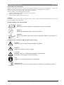
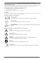
SAFETY
The following symbols indicate potentially dangerous situations. Always read this information carefully and take all necessary pre-
cautions to safeguard people and property.
VISIBLE SYMBOLS ON THE MACHINE
WARNING!
Read all the instructions carefully before performing any operation on the machine.
WARNING!
Do not wash the machine with direct or pressurized water jets.
WARNING!
Do not use the machine on slopes with a gradient exceeding that is defined in the specifications sec-
tion.
SYMBOLS THAT APPEAR ON THE INSTRUCTION FOR USE
DANGER!
It indicates a dangerous situation with risk of death for the operator.
WARNING!
It indicates a potential risk of injury for people.
CAUTION!
It indicates a caution, or a remark related to important or useful functions.
Pay attention to the paragraphs marked by this symbol.
NOTE
It indicates a remark related to important or useful functions.
CONSULTATION
It indicates the necessity to refer to the Instruction for Use manual before performing any procedure.

INSTRUCTION FOR USE ENGLISH
4
GENERAL SAFETY INSTRUCTION
Specific warnings and cautions to inform about potential damages to people and machine are shown below.
DANGER!
• This machine must be operated by trained and authorized personnel according to guidance of the manual.
• Before performing any cleaning, maintenance, repair or replacement procedure, read all the instructions carefully,
ensure to turn the machine OFF and disconnect the battery connector.
• Do not operate the machine near toxic, dangerous, flammable and/or explosive powders, liquids or vapour. This
machine is not suitable for collecting dangerous powders.
• Do not wear jewelry when working near electrical components.
• Do not work under the lifted machine without supporting it with safety stands.
• When using lead (WET) batteries, they may emit inflammable gas under normal use, must keep sparks, flames,
smoking materials and radiating, illuminating and burning items away from the batteries.
• When charging lead (WET) batteries, they may emit hydrogen gas which may cause explosive. Must ensure the
charging environment is well ventilated and away from potential flames.
WARNING!
• This machine is intended for COMMERCIAL USE, for example in hotels, schools, hospitals, factories, shops,
offices and rental businesses.
• Machines left unattended shall be secured against unintentional movement.
• In order to prevent unauthorized use of the machine, the power source shall be switched off or locked, for example
by removing the key of the main switch or the ignition key.
• Check the machine carefully before each use. Ensure that all the components have been well assembled before
use. Loose components may cause damage to people and properties.
• Before using the battery charger, ensure that the values of frequency and voltage indicated on the machine serial
number label match those of mains.
• Never move the machine by pulling the battery charger cable. Do not allow the charging cable to become damaged
by a door closing, or sharp corners. Do not run the machine over the battery charger cable. Keep the battery
charger cable away from heated surfaces.
• Do not charge the batteries if the battery charger cable or the plug are damaged.
• To reduce the risk of fire, electric shock, or injury, make sure machine is off before leaving.
• Use or store the machine indoors in dry conditions, it is not allowed for outdoor use.
• The machine storage and working temperature must be between 0 °C and +40 °C, the humidity of air must be
between 30% - 95%.
• Do not use the machine on slopes with a gradient exceeding the specifications shown.
• When using and handling floor cleaning detergents, follow the instructions on the labels of the detergent bottles
and wear suitable gloves and other protective devices.
• Use brushes and pads supplied with the machine or defined in the manual. Using other brushes or pads could
reduce safety.
• In case of machine malfunctions, ensure that these are not due to lack of maintenance. If necessary, request assis-
tance from the authorized personnel or from an authorized Service Center.
• Take all necessary precautions to prevent hair, jewelry, and loose clothes from being caught by the machine mov-
ing parts.
• Do not use the machine in particularly dusty areas.
• Do not wash the machine with direct or pressured water jets, or with corrosive substances.
• Do not bump into shelves or scaffoldings, especially where there is a risk of falling objects.
• Do not lean liquid containers on the machine, use the relevant can holder.
• To avoid damaging the floor, do not allow the brush/pad to operate while the machine is stationary.
• In case of fire, use a dry powder fire extinguisher. Do not use liquid fire extinguishers.

INSTRUCTION FOR USE ENGLISH
5
• Do not remove or modify the machine stickers.
• Do not tamper with the machine safety guards and follow the scheduled maintenance instructions closely.
• Pay attention during machine transportation when temperature is below freezing point. The water in the recovery
tank and in the hoses could freeze and cause serious damage to the machine.
• If spare parts need be replaced, order ORIGINAL spare parts from an Authorized Dealers or Retailers.
• Return the machine to the Service Center if it doesn’t work as usual or it is in condition such as damaged, placed
outdoors, dropped into water.
• To ensure machine proper and safe operation, the scheduled maintenance shown in the relevant chapter of this
Manual, must be performed by the authorized personnel or an authorized Service Center.
• The machine must be properly disposed of, due to the presence of toxic-harmful materials (batteries, etc.), which
are subject to standards that require disposal in special centers (see Scrapping chapter).
• This machine is a cleaning tool only, not for, and is not intended for any other purpose.
• Always keep the openings free from dust, hairs and any other foreign material which could reduce the air flow.
Do not use the machine if the openings are clogged.
• Use the machine only where proper lighting is provided.
• This machine is not intended for use by persons (including children) with reduced physical, sensory or mental
capabilities, or lack of experience and knowledge.
• Close attention is necessary when used near children.
• Children should be supervised to ensure that they do not play with the machine.
• While using this machine, take care not to cause damage to people or objects.
• Cleaning and user maintenance shall not be made by children without supervision.
• Operators shall be adequately instructed on the use of these machines.

INSTRUCTION FOR USE ENGLISH
6
MACHINE DESCRIPTION
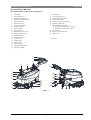
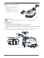
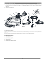
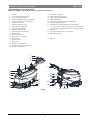
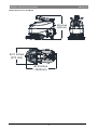
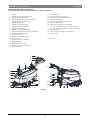
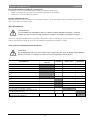
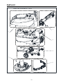
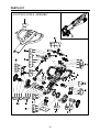
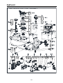
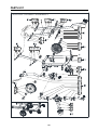
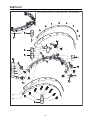
MACHINE STRUCTURE (as shown in Figure 1)
1. Handlebar
2. Safety switch lever
3. Handlebar adjusting lever
4. Recovery water drain hose
5. Recovery tank lid
6. Fresh water cover
7. Cover retention chain
8. Filling hose neck
9. Recovery tank
10. Solution tank
11. Brush deck bumper wheel
12. Brush/pad-holder deck
13. Brush/pad-holder
14. Solution level hose
15. Solenoid valve
16. Solution filter
17. Front wheels
18. Squeegee knobs
19. Squeegee lifting handle
20. Squeegee assembly
21. Control panel
22. Accessory parts box (*)
23. Battery charge cable holder
24. Battery charge cable
25. Security cover of charging jack
26. Charging signal lights
27. Deck lifting/lowering pedal
a) Pedal position when deck is lowered
b) Pedal position when deck is lifted
28. Caster wheel
29. Recovery water drain hose
30. Outlet cover
(*): Optional
Figure 1
3
7
5
6
2
1
8
9
10
11
12
13
14
16
17
1819
21
23
24
25
26
28
27A
27B
29 30
15
4
20
22
Figure 1

INSTRUCTION FOR USE ENGLISH
7
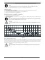
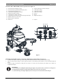
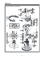
CONTROL PANEL (as shown in Figure 2)
31. Discharged battery warning light (red)
32. Semi-discharged battery warning light (yellow)
33. Charged battery warning light (green)
34. Flow increase switch
35. Solution flow indicator
36. Flow decrease switch
37. Brush/pad-holder release switch
38. Normal vacuum motor model
39. One button starting
40. ECO mode
41. Serial number plate/technical data
42. Charging red LED
43. Charging yellow LED
44. Charging green LED
45. Skirt (*)
46. Brush
47. Pad-holder (*)
(*): Optional
Figure 2
31 32 33
34
36
35
40
39
38 37
41
42
43
44 46 47
45
DISPLAY WINDOW OF CHARGER INDICATON LIGHT (as shown in Figure 2)
1. At the beginning of charging, the red LED (42) of charger is normally on. It is the first stage of charging.
2. After charging some time, the red LED (42) turns off, the yellow LED (43) turns on, this is the second stage of charging.
3. After the charging is finished, the yellow LED (43) is off, the green LED (44) turns on to indicate that the battery is fully charged.
NOTE
When charging, if the yellow LED (48) of charger is flashing, it may be caused by: Battery and charger does
not match, battery is not connected well, or output is short-circuited.
The red LED of charger flashing may be caused by charger internal short circuit.
Figure 2

INSTRUCTION FOR USE ENGLISH
8
MACHINE SIZE
40.2Inches
(1020mm)
22.5 Inches
(570 mm)
33Inches
(835mm)

INSTRUCTION FOR USE ENGLISH
9
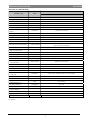
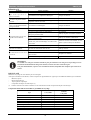
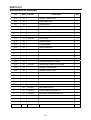
TECHNICAL PARAMETERS
Parameter Type Units
Model
AS4325B
Solution tank capacity L / Gal 25 L / 6.6 Gal.
Recovery tank capacity L / Gal 25 L / 6.6 Gal.
Machine Length mm/Inches 1020 mm / 40.1 Inches
Machine width with squeegee mm/Inches 570 mm / 22.4 Inches
Machine width without squeegee
mm/Inches 485 mm / 19.1 Inches
Machine Height (without handle)
mm/Inches 647 mm / 25.5 Inches
Machine Height (with vertical
handle) mm/Inches 1182 mm / 46.5 Inches
Working width mm/Inches 432 mm / 17 Inches
Driving wheel diameter mm/Inches 153 mm / 6 Inches
Rear wheel diameter mm/Inches 89 mm / 3.5 Inches
Brush/Pad diameter mm/Inches 432 mm / 17 Inches
Brush/Pad pressure (max) Kg/Lbs. 19 Kg / 41.8 Lbs
Solution Flow (max) per setting L / Gal per minute
(0.59/0.69/1.11/1.68) Liters
(0.16/0.18/0.29/0.44) Gallons
Sound pressure level dB (A) 69 ± 3 dB (A)
Sound pressure level in ECO
mode or in silent mode dB (A) 65 ± 3 dB (A)
Handle Vibration Level (max) m/s2 < 2.5 m/s2
Climbing capacity (max) % grade 2%
Vacuum motor power Watt / H.P. 300 W / 0.4 HP
Vacuum capacity mm/In of H2O 900 mm / 35.4 In of H2O
Vacuum capacity in ECO mode
or in silent mode mm/In of H2O 650mm / 25.6 In of H2O
Brush motor power Watt / H.P. 400 Watt / 0.54 HP
Brush speed in normal mode RPM 140 RPM
Brush speed in ECO mode RPM 100 RPM
IP protection class IP IP24
Battery Compartment Size
(L x W x H) mm/Inches (265 x 350 x 230) mm / 10.4 x 13.8 x 9.1 Inches
Voltage DC 24 V
Batteries (*) Ah 85Ah C20 / 67Ah C5
Battery run time
(standard batteries) (*) Hour Up to 4 hours
On-Board Charger (*) Volts/Amps 24V 10A
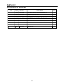
Productivity (max) m2/h 12,000 sq. ft./hr (1115 m2/h)
Machine weight with empty tanks
(without batteries) Kg/Lbs. 58 Kg / 128 Lbs.
Gross Vehicle Weight (GVW) Kg/Lbs. 134 Kg / 295 Lbs.
Shipping Weight Kg/Lbs. 137 Kg / 302 Lbs.
Packing dimensions (L x W x H)
mm/Inches (1130 x 730 x 1040 mm) / (44.5 x 28.7 x 41 Inches)
(*): Optional

INSTRUCTION FOR USE ENGLISH
10
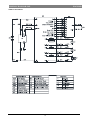
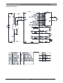
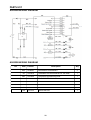
WIRING DIAGRAM

INSTRUCTION FOR USE ENGLISH
11
OPERATING GUIDE
WARNING!
On some points of the machine there are some adhesive plates indicating:
– DANGER!
– WARNING!
– CAUTION!
– CONSULTATION
While reading this Manual, the operator must pay particular attention to the symbols shown on the plates. Do not cover these
plates for any reason and immediately replace them if damaged.
BATTERY CHECK/SETTING ON A NEW MACHINE
WARNING!
The electric components of the machine can be seriously damaged if the batteries are either improperly in-
stalled or connected. The batteries must be installed by qualified personnel only. Set the function of the elec-
tronic board and the built-in battery charger according to the type of batteries used (WET or GEL/AGM
batteries). Check the batteries for damage before installation. Disconnect the battery connector and the battery
charger plug. Handle the batteries with great care. Install the battery terminal protection caps supplied with
the machine.
NOTE
The machine requires two 12 V batteries, connected according to the diagram (Figure 3).
Figure 3

INSTRUCTION FOR USE ENGLISH
12
The machine can be supplied in one of the following modes:
A) Batteries (WET or GEL/ AGM) already installed and charged
1. Check that the batteries are connected to the machine with the connector (B, Figure 3).
2. Pressing the switch (39 Figure 2). If the green warning light (33) turns on, the batteries are fully charged. If the yellow (32) or red
warning light (31) turns on, the batteries must be charged (see the procedure in Maintenance chapter).
B) Without batteries
1. Buy appropriate batteries (see the Technical Data paragraph).
2. For battery choice and installation, apply to qualified battery Retailers.
3. Set the machine and the battery charger according to the type of batteries (WET or GEL/ AGM), as shown in the next paragraph.
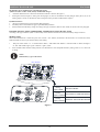
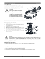
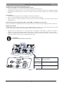
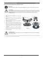
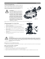
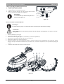
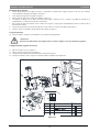
BATTERY INSTALLATION AND BATTERY TYPESETTING (WET OR GEL/ AGM)
According to the type of batteries (WET or GEL/AGM), set the machine and electronic board of the battery charger as follows:
Machine setting
When One-button Start S3 is turned off, press water volume + and - buttons (S5 and S6) at the same time, 0.5 seconds later, LED1,
LED2 and LED3 are all lit up to enter the battery mode setting:
1. Then press water volume + or – to switch between “WET”, “GEL/AMG” and “DIS-EV”. In the the mode of “WET”, Red light is
on. And “GEL/AGM”, light is green. “DIS-EV”, light is yellow.
2. Press One-button Start to finish setting and exit, turn off machine to store and update all battery setting, when it’s on, it will work
as setting.
NOTE
Default battery type is GEL/AGM.
S1
S2
S3 S5
S4 S6
LED4
LED5
LED6
LED7
LED8
LED9
LED10
LED1 LED2LED3
WET BATTERIES
DISCOVER EV AGM BATTERIES
GENERAL GEL/AGM BATTERIES
LED1
Light is Red
LED2
Light is Yellow
LED3
Light is Green
Figure 4
Figure 4

INSTRUCTION FOR USE ENGLISH
13
Battery installation
3. Open the recovery tank cover (5, Figure 1) and check that the recovery tank (9, Figure 1) is empty; otherwise empty it with the
drain hose. (4, Figure 1)
4. Close the recovery tank cover (5, Figure 1).
5. Move the recovery tank kit (A, Figure 3) carefully.
6. The machine is supplied with cables suitable to install 2X12V batteries. Carefully put the batteries into the compartment, then install
them correctly.
7. Route and install the battery cable as shown in (Figure3), then carefully tighten the nut on each battery terminal.
8. Place the protection cap on each terminal, then connect the battery connector (B, Figure 3).
9. Carefully put it back the recovery tank kit (A, Figure 3).
Battery charging
10. Charge the batteries. (See procedures in maintenance chapter).
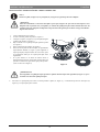
CAUTION!
Cut off all the power of the machine before perform the following procedure!
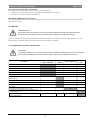
Battery charger setting
11. Remove the screws (A, B, C, Figure 4.1).
12. Open the charger and find the sw1 (D, Figure 4.1).
13. Set the switches as the table of Figure 4.1.
14. Install the screws (A, B, C, Figure 4.1) after setting complete.
DP1 DP2
OFF
ON
SW1
DP1 DP2 CHARGING CURVE
ON OFF IUIa Wet
OFF
IUUa Fullriver AGM
ON IUIa Discover AGM
ON
ON
OFF
OFF
SKETCHES
A
B
C
Figure 4.1
D
Figure 4.1

INSTRUCTION FOR USE ENGLISH
14
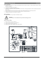
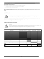
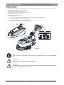
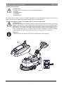
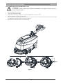
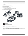
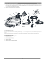
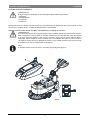
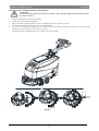
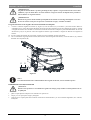
BRUSH/PAD-HOLDER INSTALLATION AND REMOVAL
NOTE
Install either the brush (A, Figure 5) or pad-holder (B and C, Figure 5) according to the type of floor to be
cleaned.
CAUTION!
Before installation or removal of brush or pad-holder, make sure all the switches on machine are in off position
and lifting up the squeegee and the brush/pad-holder deck from the floor. The operator must be equipped with
suitable personnel protection devices such as gloves to reduce the risk of accidents.
Proceed as following:
1. Shut off the power switch (39, Figure 2).
2. Lift the deck by pressing the pedal (27, Figure 1).
3. Place the brushes (A, Figure 5) or the pad-holder (B,
Figure 5) under the deck (12, Figure 1).
4. Lower the deck on the brushes/pad-holders by pressing the
pedal (27, Figure 1).
5. Press the start switch (39, Figure 2).
6. Press one of the Brush/forward gear safety switch lever (2,
Figure 1) to engage the brush/pad-holder, then release it. If
necessary, repeat the procedure until the brushes/pad-
holders are engaged.
7. If Step No.6 above proves to be difficult, use the manual
method by turning the brush/pad-holder in the direction
opposite to the normal turning direction, and it can be taken
off. (as shown in Figure 5)
Figure 5
AB
C
WARNING!
To engage the brush/pad-holder press the safety switch lever (2, Figure 1) which turns on the brush/pad-holder
motor.
8. To remove the brush/pad-holder lift the deck by pressing the pedal (27, Figure 1), then press the switch (37, Figure 2), the brush/pad-
holder will be removed.
Figure 5

INSTRUCTION FOR USE ENGLISH
15
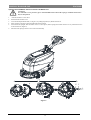
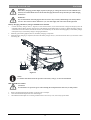
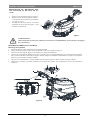
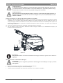
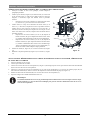
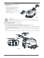
SQUEEGEE ASSEMBLE INSTALLATION AND REMOVAL
CAUTION!
It is advisable to wear protective gloves when installation and removal the squeegee assemble because there
may be sharp debris.
1. Push the machine to a level floor.
2. Ensure that the machine is off.
3. Lower the brush/pad-holder deck (12, Figure 1) by lifting the pedal (36), Brush on the floor.
4. Place squeegee in the place between brush deck and front wheel.
5. Fix stud A to the openg B, then fix another screw C to the open D, fasten squeegee knob and connect recovery water drain hose F
to the connector E (Figure 6).
6. Disconnect the squeegee in the reverse order of disassembly.
A
DD
E
Figure 6
A
B
F
C
Figure 6

INSTRUCTION FOR USE ENGLISH
16
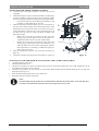
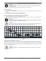
SOLUTION OR WASHING WATER TANK
FILLING
1. Open the water inlet cover (A, Figure 7).
2. Fill with water or solution suitable for work
performance.
The solution temperature must not ex-ceed
+104°F (+40°C).
3. Do not overfill the tank, refer to water level
indicator (B, Figure 7) for the water volume.
B
A
Figure 7
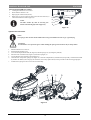
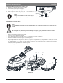
MACHINE START AND STOP
Starting the machine
1. Prepare the machine as shown in the previous paragraph.
2. Push the machine to the area to be cleaned, by pushing it with the hands on the handlebar (I, Figure 8).
3. Lower the brush/pad-holder deck (M, Figure 8) and the squeegee (L) by lifting the pedal (K).
4. Press the start switch (G, Figure 8). Check that the green warning light (C) turns on (charged battery). If the yellow (B) or red
warning light (A) turns on, Shutoff the power switch (G, Figure 8) and charge the batteries (see the procedure in Maintenance
chapter).
5. Press the washing water flow control switches (D, Figure 8) as necessary, depending on the type of cleaning to be performed.
6. Start cleaning by pushing the machine with the hands on the handlebar (I) and pressing the safety switch lever (J).
WARNING!
Use only low-foam and non-flammable detergents, intended for automatic scrubber applications.
Figure 7
Figure 8
La page est en cours de chargement...
La page est en cours de chargement...
La page est en cours de chargement...
La page est en cours de chargement...
La page est en cours de chargement...
La page est en cours de chargement...
La page est en cours de chargement...
La page est en cours de chargement...
La page est en cours de chargement...
La page est en cours de chargement...
La page est en cours de chargement...
La page est en cours de chargement...
La page est en cours de chargement...
La page est en cours de chargement...
La page est en cours de chargement...
La page est en cours de chargement...
La page est en cours de chargement...
La page est en cours de chargement...
La page est en cours de chargement...
La page est en cours de chargement...
La page est en cours de chargement...
La page est en cours de chargement...
La page est en cours de chargement...
La page est en cours de chargement...
La page est en cours de chargement...
La page est en cours de chargement...
La page est en cours de chargement...
La page est en cours de chargement...
La page est en cours de chargement...
La page est en cours de chargement...
La page est en cours de chargement...
La page est en cours de chargement...
La page est en cours de chargement...
La page est en cours de chargement...
La page est en cours de chargement...
La page est en cours de chargement...
La page est en cours de chargement...
La page est en cours de chargement...
La page est en cours de chargement...
La page est en cours de chargement...
La page est en cours de chargement...
La page est en cours de chargement...
La page est en cours de chargement...
La page est en cours de chargement...
La page est en cours de chargement...
La page est en cours de chargement...
La page est en cours de chargement...
La page est en cours de chargement...
La page est en cours de chargement...
La page est en cours de chargement...
La page est en cours de chargement...
La page est en cours de chargement...
La page est en cours de chargement...
La page est en cours de chargement...
La page est en cours de chargement...
La page est en cours de chargement...
La page est en cours de chargement...
La page est en cours de chargement...
La page est en cours de chargement...
La page est en cours de chargement...
La page est en cours de chargement...
La page est en cours de chargement...
La page est en cours de chargement...
La page est en cours de chargement...
La page est en cours de chargement...
La page est en cours de chargement...
La page est en cours de chargement...
La page est en cours de chargement...
La page est en cours de chargement...
La page est en cours de chargement...
La page est en cours de chargement...
La page est en cours de chargement...
La page est en cours de chargement...
La page est en cours de chargement...
La page est en cours de chargement...
La page est en cours de chargement...
La page est en cours de chargement...
La page est en cours de chargement...
La page est en cours de chargement...
La page est en cours de chargement...
La page est en cours de chargement...
La page est en cours de chargement...
La page est en cours de chargement...
-
 1
1
-
 2
2
-
 3
3
-
 4
4
-
 5
5
-
 6
6
-
 7
7
-
 8
8
-
 9
9
-
 10
10
-
 11
11
-
 12
12
-
 13
13
-
 14
14
-
 15
15
-
 16
16
-
 17
17
-
 18
18
-
 19
19
-
 20
20
-
 21
21
-
 22
22
-
 23
23
-
 24
24
-
 25
25
-
 26
26
-
 27
27
-
 28
28
-
 29
29
-
 30
30
-
 31
31
-
 32
32
-
 33
33
-
 34
34
-
 35
35
-
 36
36
-
 37
37
-
 38
38
-
 39
39
-
 40
40
-
 41
41
-
 42
42
-
 43
43
-
 44
44
-
 45
45
-
 46
46
-
 47
47
-
 48
48
-
 49
49
-
 50
50
-
 51
51
-
 52
52
-
 53
53
-
 54
54
-
 55
55
-
 56
56
-
 57
57
-
 58
58
-
 59
59
-
 60
60
-
 61
61
-
 62
62
-
 63
63
-
 64
64
-
 65
65
-
 66
66
-
 67
67
-
 68
68
-
 69
69
-
 70
70
-
 71
71
-
 72
72
-
 73
73
-
 74
74
-
 75
75
-
 76
76
-
 77
77
-
 78
78
-
 79
79
-
 80
80
-
 81
81
-
 82
82
-
 83
83
-
 84
84
-
 85
85
-
 86
86
-
 87
87
-
 88
88
-
 89
89
-
 90
90
-
 91
91
-
 92
92
-
 93
93
-
 94
94
-
 95
95
-
 96
96
-
 97
97
-
 98
98
-
 99
99
-
 100
100
-
 101
101
-
 102
102
-
 103
103


Nilfisk AS4325B-CAN DISC 17 IN Le manuel du propriétaire
- Catégorie
- Machine à plancher
- Taper
- Le manuel du propriétaire
- Ce manuel convient également à
dans d''autres langues
Documents connexes
Autres documents
-
Clarke Vantage 14 Mode d'emploi
-
Nilfisk-ALTO SCRUBTEC 343.2 Manuel utilisateur
-
Nilfisk-Advance BR 752C Instructions For Use Manual
-
-
-
-
-
-