Ingersoll-Rand 9RSS Operation and Maintenance Manual
- Catégorie
- Outils électroportatifs
- Taper
- Operation and Maintenance Manual

Refer All Communications to the Nearest
Ingersoll–Rand Office or Distributor.
Ingersoll–Rand Company 1999
Printed in U.S.A.
03539616
Form P7085
Edition 5
September, 1999
OPERATION AND MAINTENANCE MANUAL FOR
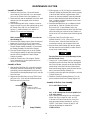
SERIES 9RS, 9S AND 9T ANGLE WRENCHES
Series 9RS, 9S and 9T Angle Wrenches are designed for heavy–duty close–quarter threaded
fastener applications which require precise torque repeatability.
Ingersoll–Rand is not responsible for customer modification of tools for applications on which
Ingersoll–Rand was not consulted.
IMPORTANT SAFETY INFORMATION ENCLOSED.
READ THIS MANUAL BEFORE OPERATING TOOL.
IT IS THE RESPONSIBILITY OF THE EMPLOYER TO PLACE THE INFORMATION
IN THIS MANUAL INTO THE HANDS OF THE OPERATOR.
FAILURE TO OBSERVE THE FOLLOWING WARNINGS COULD RESULT IN INJURY.
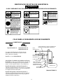
PLACING TOOL IN SERVICE
• Always operate, inspect and maintain this tool in
accordance with American National Standards
Institute Safety Code for Portable Air Tools
(ANSI B186.1).
• For safety, top performance, and maximum durability
of parts, operate this tool at 90 psig (6.2 bar/620 kPa)
maximum air pressure at the inlet with 1/2” (13 mm)
inside diameter air supply hose.
• Always turn off the air supply and disconnect the air
supply hose before installing, removing or adjusting
any accessory on this tool, or before performing any
maintenance on this tool.
• Do not use damaged, frayed or deteriorated air hoses
and fittings.
• Be sure all hoses and fittings are the correct size and
are tightly secured. See Dwg. TPD905–1 for a typical
piping arrangement.
• Always use clean, dry air at 90 psig maximum air
pressure. Dust, corrosive fumes and/or excessive
moisture can ruin the motor of an air tool.
• Do not lubricate tools with flammable or volatile
liquids such as kerosene, diesel or jet fuel.
• Do not remove any labels. Replace any damaged label.
USING THE TOOL
• Always wear eye protection when operating or
performing maintenance on this tool.
• Always wear hearing protection when operating this
tool.
• Keep hands, loose clothing and long hair away from
rotating end of tool.
• Note the position of the reversing lever before
operating the tool so as to be aware of the direction of
rotation when operating the throttle.
• Anticipate and be alert for sudden changes in motion
during start up and operation of any power tool.
• Keep body stance balanced and firm. Do not
overreach when operating this tool. High reaction
torques can occur at or below the recommended air
pressure.
• Tool accessories may continue to rotate briefly after
throttle is released.
• Air powered tools can vibrate in use. Vibration,
repetitive motions or uncomfortable positions may be
harmful to your hands and arms. Stop using any tool
if discomfort, tingling feeling or pain occurs. Seek
medical advice before resuming use.
• Use accessories recommended by Ingersoll–Rand.
• Use only impact sockets and accessories. Do not use
hand (chrome) sockets or accessories.
• The Throttle Valve Cap is under pressure from the
Throttle Valve Spring. Use care when removing the
Throttle Valve Cap. (On tools where applicable.)
• Whenever the Angle Head is installed or repositioned,
the Throttle Lever must be positioned so that reaction
torque will not tend to retain the throttle in the “ON”
position.
• This tool is not designed for working in explosive
atmospheres.
• This tool is not insulated against electric shock.
The use of other than genuine Ingersoll–Rand replacement parts may result in safety hazards, decreased tool performance, and
increased maintenance, and may invalidate all warranties.
Repairs should be made only by authorized trained personnel. Consult your nearest Ingersoll–Rand Authorized Servicenter.
F
E
P
TPD1392

2
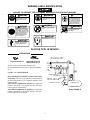
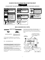
WARNING LABEL IDENTIFICATION
FAILURE TO OBSERVE THE FOLLOWING WARNINGS COULD RESULT IN INJURY.
Always wear eye protection
when operating or perform-
ing maintenance on this
tool.
WARNING
WARNING
Always wear hearing
protection when operating
this tool.
Always turn off the air sup-
ply and disconnect the air
supply hose before install-
ing, removing or adjusting
any accessory on this tool,
or before performing any
maintenance on this tool.
WARNING
WARNING
Do not use damaged, frayed
or deteriorated air hoses
and fittings.
WARNING
Keep body stance balanced
and firm. Do not overreach
when operating this tool.
WARNING
Operate at 90 psig (6.2 bar/
620 kPa) Maximum air pressure.
90 psig
(6.2bar/620kPa)
Do not carry the tool by the
hose.
Air powered tools can
vibrate in use. Vibration, re-
petitive motions or uncomfort-
able positions may be harmful
to your hands and arms. Stop
using any tool if discomfort,
tingling feeling or pain oc-
curs. Seek medical advice
before resuming use.
WARNING
WARNING
PLACING TOOL IN SERVICE
LUBRICATION
Ingersoll–Rand No. 10 Ingersoll–Rand No. 28
Ingersoll–Rand No. 66
Always use an air line lubricator with these tools.
We recommend the following Filter–Lubricator–Regulator
Unit:
For USA – No. C28–04–FKG0–28
Before starting the tool and after each two or three hours
of operation, unless the air line lubricator is used, detach the
air hose and inject about 2.5 cc of Ingersoll–Rand No. 10 Oil
into the air inlet.
After each forty–eight hours of operation, or as experience
indicates, inject about 1 cc of Ingersoll–Rand No. 28 Grease
into the gear case Grease Fitting.
After each forty–eight hours of operation, or as experience
indicates, inject about 1 cc of Ingersoll–Rand No. 66 Grease
into the angle head Grease Fitting.
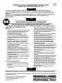
MAIN LINES 3 TIMES
AIR TOOL INLET SIZE
TO
AIR
SYSTEM
TO
AIR
TOOL
LUBRICATOR
REGULATOR
FILTER
BRANCH LINE 2 TIMES
AIR TOOL INLET SIZE
DRAIN REGULARLY
COMPRESSOR
(Dwg. TPD905–1)

3
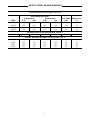
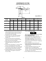
HOW TO ORDER AN ANGLE WRENCH
INLINE HANDLE REVERSIBLE STALL
Torque Range (Soft Draw)
50 psi pressure 90 psi pressure Free Speed Square Drive
Model ft–lb Nm ft–lb Nm rpm in
9RSM53 25.0 33.9 40.0 54.2 665 1/2
9RSN53 32.0 43.4 50.0 67.8 535 1/2
9RSP53 39.0 52.9 58.0 78.6 425 1/2
9RSQ83 45.0 61.0 82.0 111.2 300 1/2
INLINE HANDLE NONREVERSIBLE STALL
9SQ83 50.0 67.8 85.0 115.2 355 1/2
INLINE HANDLE NONREVERSIBLE SHUT–OFF
9TM53 27.0 36.6 40.0 54.2 780 1/2
9TN53 35.0 47.5 50.0 67.8 630 1/2
9TP53 42.0 57.0 65.0 88.1 500 1/2
9TQ83 50.0 67.8 85.0 115.2 355 1/2

Adressez toutes vos communications au Bureau
Ingersoll–Rand ou distributeur le plus proche.
Ingersoll–Rand Company 1999
Imprimé aux É.U.
MANUEL D’EXPLOITATION ET D’ENTRETIEN DES
CLÉS D’ANGLE DES SÉRIES 9RS, 9S ET 9T
NOTE
Les clés d’angle des séries 9RS, 9S et 9T sont destinées au serrage dans des espaces
restreints des grosses fixations filetées nécessitant une répétabilité précise du couple.
Ingersoll–Rand ne peut être tenu responsable de la modification des outils par le client pour les
adapter à des applications qui n’ont pas été approuvées par Ingersoll–Rand.
ATTENTION
D’IMPORTANTES INFORMATIONS DE SECURITÉ SONT JOINTES.
LIRE CE MANUEL AVANT D’UTILISER L’OUTIL.
L’EMPLOYEUR EST TENU À COMMUNIQUER LES INFORMATIONS
DE CE MANUEL AUX EMPLOYÉS UTILISANT CET OUTIL.
LE NON RESPECT DES AVERTISSEMENTS SUIVANTS PEUT CAUSER DES BLESSURES
MISE EN SERVICE DE L’OUTIL
S Toujours exploiter, inspecter et entretenir cet outil
conformément au Code de sécurité des outils
pneumatiques portatifs de l’American National
Standards Institute (ANSI B186.1).
• Pour la sécurité, les performances optimales et la
durabilité maximale des pièces, cet outil doit être
connecté à une alimentation d’air comprimé de
6,2 bar (620 kPa) maximum à l’entrée, avec un flexible
de 13 mm de diamètre intérieur.
• Couper toujours l’alimentation d’air comprimé et
débrancher le flexible d’alimentation avant d’installer,
déposer ou ajuster tout accessoire sur cet outil, ou
d’entreprendre une opération d’entretien quelconque
sur l’outil.
• Ne pas utiliser des flexibles ou des raccords
endommagés, effilochés ou détériorés.
• S’assurer que tous les flexibles et les raccords sont
correctement dimensionnés et bien serrés. Voir Plan
TPD905–1 pour un exemple type d’agencement des
tuyauteries.
• Utiliser toujours de l’air sec et propre à une pression
maximum de 6,2 bar. La poussière, les fumées
corrosives et/ou une humidité excessive peuvent
endommager le moteur d’un outil pneumatique.
• Ne jamais lubrifier les outils avec des liquides
inflammables ou volatiles tels que le kérosène, le gasol
ou le carburant d’aviation.
• Ne retirer aucune étiquette. Remplacer toute étiquette
endommagée.
UTILISATION DE L’OUTIL
• Porter toujours des lunettes de protection pendant
l’utilisation et l’entretien de cet outil.
• Porter toujours une protection acoustique pendant
l’utilisation de cet outil.
• Tenir les mains, les vêtements flous et les cheveux
longs, éloignés de l’extrémité rotative de l’outil.
• Noter la position du levier d’inversion avant de mettre
l’outil en marche de manière à savoir dans quel sens il
va tourner lorsque la commande est actionnée.
• Prévoir, et ne pas oublier, que tout outil motorisé est
susceptible d’à–coups brusques lors de sa mise en
marche et pendant son utilisation.
• Garder une position équilibrée et ferme. Ne pas se
pencher trop en avant pendant l’utilisation de cet
outil. Des couples de réaction élevés peuvent se
produire à, ou en dessous, de la pression d’air
recommandée.
• La rotation des accessoires de l’outil peut continuer
pendant un certain temps après le relâchement de la
gâchette.
• Les outils pneumatiques peuvent vibrer pendant
l’exploitation. Les vibrations, les mouvements
répétitifs et les positions inconfortables peuvent causer
des douleurs dans les mains et les bras. N’utiliser plus
d’outils en cas d’inconfort, de picotements ou de
douleurs. Consulter un médecin avant de
recommencer à utiliser l’outil.
• Utiliser les accessoires recommandés par
Ingersoll-Rand.
• N’utiliser que les douilles et les accessoires pour clés à
chocs. Ne pas utiliser les douilles et accessoires
(chromés) de clés manuelles.
• Le chapeau de la soupape de commande est soumis à
la pression du ressort de soupape. Prendre les soins
nécessaires lors de la dépose du chapeau de soupape
de commande. (Sur les outils concernés).
• A chaque fois que le renvoi d’angle est installé ou
repositionné, le levier de commande doit être
positionné de manière à ce que le couple de réaction
n’ait pas tendance à maintenir le levier de commande
en position ”MARCHE”.
• Cet outil n’est pas conçu pour fonctionner dans des
atmosphères explosives.
• Cet outil n’est pas isolé contre les chocs électriques.
NOTE
L’utilisation de rechanges autres que les pièces d’origine Ingersoll–Rand peut causer des risques d’insécurité, réduire les
performances de l’outil et augmenter l’entretien, et peut annuler toutes les garanties.
Les réparations ne doivent être effectuées que par des réparateurs qualifiés autorisés. Consultez votre Centre de Service
Ingersoll–Rand le plus proche.
F

5
SIGNIFICATION DES ETIQUETTES D’AVERTISSEMENT
ATTENTION
LE NON RESPECT DES AVERTISSEMENTS SUIVANTS PEUT CAUSER DES BLESSURES
Porter toujours des lunettes
de protection pendant
l’utilisation et l’entretien de
cet outil.
ATTENTION ATTENTION
Porter toujours une
protection acoustique
pendant l’utilisation de cet
outil.
Les outils pneumatiques
peuvent vibrer pendant
l’exploitation. Les vibrations,
les mouvements répétitifs et les
positions inconfortables
peuvent causer des douleurs
dans les mains et les bras.
N’utiliser plus d’outils en cas
d’inconfort, de picotements ou
de douleurs. Consulter un
médecin avant de recommencer
à utiliser l’outil.
ATTENTION
Ne pas transporter l’outil
par son flexible.
ATTENTION
ATTENTION
Garder une position équilibrée et
ferme. Ne pas se pencher trop
en avant pendant
l’utilisation de cet outil.
ATTENTION
Utiliser de l’air comprimé
à une pression maximum
de 6,2 bar (620 kPa).
90 psig
(6.2bar/620kPa)
Couper toujours l’alimentation
d’air comprimé et débrancher le
flexible d’alimentation avant
d’installer, déposer ou ajuster
tout accessoire sur cet outil, ou
d’entreprendre une opération
d’entretien quelconque sur l’ou-
til.
ATTENTION
ATTENTION
Ne pas utiliser des flexibles ou
des raccords endommageés,
effilochés ou détériorés.
MISE EN SERVICE DE L’OUTIL
LUBRIFICATION
Ingersoll–Rand No. 10 Ingersoll–Rand No. 28
Ingersoll–Rand No. 66
Utiliser toujours un lubrificateur avec ces outils. Nous
recommandons l’emploi du filtre–régulateur–lubrificateur
suivant :
É.U. – No. C28–04–FKG0–28
Avant de mettre l’outil en marche et toutes les deux ou
trois heures defonctionnement, si un lubrificateur de ligne
n’est pas utilisé, débrancher le flexible d’alimentation et
verser environ 2,5 cm
3
d’huile Ingersoll–Rand No 10. dans le
raccord d’admission de l’outil.
Toutes les quarante–huit heures de fonctionnement, ou en
fonction de l’expérience, injecter environ 1cm
3
de graisse
Ingersoll–Rand No. 28 dans le raccord de graissage du boîtier
d’engrenages.
Toutes les quarante–huit heures de fonctionnement, ou en
fonction de l’expérience, injecter environ 1cm
3
de graisse
Ingersoll–Rand No. 66 dans le raccord de graissage du renvoi
d’angle.
TUYAUTERIE PRINCIPALE
AU MOINS 3 FOIS LA DIMEN-
SION DE L’ADMISSION D’AIR
DE L’OUTIL
VERS LE
RÉSEAU D’AIR
COMPRIMÉ
VERS
L’OUTIL
PNEU-
MATIQUE
LUBRIFICATEUR
RÉGULATEUR
FILTRE
LIGNE SECONDAIRE AU
MOINS 2 FOIS LA DIMEN-
SION DE L’ADMISSION
D’AIR DE L’OUTIL
VIDANGER
RÉGULIÈREMENT
COMPRESSEUR
(Plan TPD905–1)

6
MISE EN SERVICE DE L’OUTIL
SPÉCIFICATIONS
Modèle Dispositif de
couple
Plage de couple
(Serrage élastique)
Vitesse libre entr.
carré
50 psi
ft–lbs (Nm)
90 psi
ft–lbs (Nm)
tr/mn in.
9RSM53 calage 25,0 (33,9) 40,0 (54,2) 665 1/2
9RSN53 calage 32,0 (43,4) 50,0 (67,8) 535 1/2
9RSP53 calage 39,0 (52,9) 58,0 (78,6) 425 1/2
9RSQ83 calage 45,0 (61,0) 82,0 (111,2) 300 1/2
9SQ83 calage 50,0 (67,8) 85,0 (115,2) 355 1/2
9TM53 arrêt 27,0 (36,6) 40,0 (54,2) 780 1/2
9TN53 arrêt 35,0 (47,5) 50,0 (67,8) 630 1/2
9TP53 arrêt 42,0 (57,0) 65,0 (88,1) 500 1/2
9TQ83 arrêt 50,0 (67,8) 85,0 (115,2) 355 1/2

Toda comunicación se deberá dirigir a la oficina o
al distribuidor Ingersoll–Rand más próximo.
Ingersoll–Rand Company 1999
Impreso en EE. UU.
MANUAL DE USO Y MANTENIMIENTO PARA LLAVES
ANGULARES MODELOS 9RS, 9S Y 9T
NOTA
Las Llaves Angulares Modelos 9RS, 9S y 9T están diseñadas para trabajo pesado en
aplicaciones de abrazadera roscada de distancia mínima que requieran repetibilidad de par
precisa.
Ingersoll–Rand no aceptará responsabilidad alguna por la modificación de las herramientas
efectuada por el cliente para las aplicaciones que no hayan sido consultadas con
Ingersoll–Rand.
AVISO
SE ADJUNTA INFORMACIÓN IMPORTANTE DE SEGURIDAD.
LEA ESTE MANUAL ANTES DE USAR LA HERRAMIENTA.
ES RESPONSABILIDAD DE LA EMPRESA ASEGURARSE DE QUE EL OPERARIO
ESTÉ AL TANTO DE LA INFORMACIÓN QUE CONTIENE ESTE MANUAL.
EL HACER CASO OMISO DE LOS AVISOS SIGUIENTES PODRÍA OCASIONAR LESIONES.
PARA PONER LA HERRAMIENTA EN
SERVICIO
S Utilice, examine y mantenga siempre esta herramienta
conforme al código de seguridad para herramientas
neumáticas portátiles de la American National
Standards Institute (ANSI B186.1).
• Para seguridad, máximo rendimiento y vida de
servicio de las piezas, use esta herramienta a una
presión de aire máxima de 90 psig (6,2 bar/620 kPa)
en la manguera de suministro de aire con diámetro
interno de 13 mm.
• Corte siempre el suministro de aire y desconecte la
manguera de suministro de aire antes de instalar,
desmontar o ajustar cualquier accesorio de esta
herramienta, o antes de realizar cualquier operación
de mantenimiento de la misma.
• No utilice mangueras de aire y accesorios dañados,
desgastados ni deteriorados.
• Asegúrese de que todas las mangueras y accesorios
sean del tamaño correcto y estén bien apretados. Vea
Esq. TPD905–1 para un típico arreglo de tuberías.
• Use siempre aire limpio y seco a una presión máxima
de 90 psig. El polvo, los gases corrosivos y/o el exceso
de humedad podrían estropear el motor de una
herramienta neumática.
• No lubrique las herramientas con líquidos inflamables
o volátiles tales como queroseno, gasoil o combustible
para motores a reacción.
• No saque ninguna etiqueta. Sustituya toda etiqueta
dañada.
USO DE LA HERRAMIENTA
• Use siempre protección ocular cuando utilice esta
herramienta o realice operaciones de mantenimiento
en la misma.
• Use siempre protección para los oídos cuando utilice
esta herramienta.
• Mantenga las manos, la ropa suelta y el cabello largo
alejados del extremo giratorio de la herramienta.
• Note la posición de la palanca de inversión antes de
hacer funcionar la herramienta para ser consciente de
su dirección giratoria cuando funcione el
estrangulador.
• Anticipe y esté alerta sobre los cambios repentinos en
el movimiento durante la puesta en marcha y el
manejo de toda herramienta motorizada.
• Mantenga una postura de cuerpo equilibrada y firme.
No estire demasiado los brazos al manejar la
herramienta. Pueden ocurrir reacciones de alto par a,
o a menos de, la recomendada presión de aire.
• Los accesorios de la herramienta podrían seguir
girando brevemente después de haber soltado la
palanca de estrangulación.
• Las herramientas neumáticas pueden vibrar durante
el uso. La vibración, repetición o posiciones incómodas
pueden dañarle los brazos y manos. En caso de
incomodidad, sensación de hormigueo o dolor, deje de
usar la herramienta. Consulte a un médico antes de
volver a usarla otra vez.
• Utilice únicamente los accesorios Ingersoll–Rand
recomendados.
• Utilice únicamente bocas y accesorios para llaves de
impacto. No utilice bocas o accessorios manuales
(cromados).
• La Tapa de Válvula de Estrangulación está presionada
por el Muelle de Válvula de Estrangulación. Tenga
cuidado al sacar la Tapa de Válvula de
Estrangulación. (En las herramientas que la aplican).
• Cuando se instale o reposicione la Cabeza Angular, la
Palanca de Estrangulación deberá posicionarse de
forma que la reacción de par no tienda a retener el
mando en la posición de “ON” (ACCIONAMIENTO).
• Esta herramienta no ha sido diseñada para trabajar en
ambientes explosivos.
• Esta herramienta no está aislada contra descargas
eléctricas.
NOTA
El uso de piezas de recambio que no sean las auténticas piezas Ingersoll–Rand podría poner en peligro la seguridad, reducir el
rendimiento de la herramienta y aumentar los cuidados de mantenimiento necesarios, así como invalidar toda garantía.
Las reparaciones sólo serán realizadas por personal cualificado y autorizado. Consulte con el centro de servicio Ingersoll–Rand
autorizado más próximo.
E

8
ETIQUETAS DE AVISO
AVISO
EL HACER CASO OMISO DE LOS AVISOS SIGUIENTES PODRÍA OCASIONAR LESIONES.
ADVERTENCIA
Las herramientas neumáticas
pueden vibrar durante el uso.
La vibración, los movimientos
repetitivos o las posiciones
incómodas podrían dañarle los
brazos y las manos. En caso
de incomodidad, sensación de
hormigueo o dolor, dejar de
usar la herramienta. Consultar
al médico antes de volver a uti-
lizarla.
No coger la herramienta
por la manguera para le-
vantarla.
ADVERTENCIA
Mantener una postura del cuerpo
equilibrada y firme. No estirar de-
masiado los brazos al manejar la
herramienta.
Manejar la herramienta a una
presión de aire máxima de 90
psig (6,2 bar/620 kPa).
90 psig
(6.2bar/620kPa)
Cortar siempre el suministro
de aire y desconectar la man-
guera de suministro de aire
antes de instalar, retirar o ajus-
tar cualquier accesorio de esta
herramienta, o antes de realizar
cualquier operación de man-
tenimiento de la misma.
No utilizar mangueras de aire
y accesorios dañados, des-
gastados ni deteriorados.
ADVERTENCIA
ADVERTENCIA
ADVERTENCIA
ADVERTENCIA
ADVERTENCIA
ADVERTENCIA
Use siempre protección ocular
cuando utilice esta herramienta
o realice operaciones de
mantenimiento en la misma.
Use siempre protección para
los oídos cuando utilice esta
herramienta.
PARA PONER LA HERRAMIENTA EN SERVICIO
LUBRICACIÓN
Ingersoll–Rand Nº 10 Ingersoll–Rand Nº 28
Ingersoll–Rand Nº 66
Utilice siempre un lubricador de aire comprimido con estas
herramientas. Recomendamos la siguiente unidad de
Filtro–Lubricador–Regulador:
EE.UU. – Nº C28–04–FKG0–28
Antes de poner la herramienta en marcha y después de
cada dos o tres horas de uso, a menos que se haya puesto
lubricante de línea de aire comprimido, desconecte la
manguera de aire e inyecte unos 2,5 cc de Aceite
Ingersoll–Rand Nº 10 en la admisión de aire.
Después de cada cuarenta y ocho horas de uso, o como
indique la experiencia, inyecte alrededor de 1 cc de Grasa
Ingersoll–Rand Nº 28 en el Engrasador de caja de engranajes.
Después de cada cuarenta y ocho horas de uso, o como
indique la experiencia, inyecte alrededor de 1 cc de Grasa
Ingersoll–Rand Nº 66 en el Engrasador de la cabeza angular.
TUBERÍAS PRINCIPALES 3
VECES EL TAMAÑO DE
ENTRADA DE HERRAMIENTA
NEUMÁTICA
AL SISTEMA
NEUMÁTICO
A LA
HERRA–
MIENTA
NEUMÁTICA
LUBRICADOR
REGULADOR
FILTRO
TUBERÍA DE RAMAL
2 VECES EL TAMAÑO
DE ENTRADA DE
HERRAMIENTA
NEUMÁTICA
PURGAR
PERIÓDICAMENTE
COMPRESOR
(Esq. TPD905–1)

9
PARA PONER LA HERRAMIENTA EN SERVICIO
ESPECIFICACIONES
Modelo Dispositivo de
Par
Gama de Par
(Retirada Suave)
Velocidad
Libre
Cuadradillo
50 psi
ft–lbs (Nm)
90 psi
ft–lbs (Nm)
rpm pulg.
9RSM53 calado 25,0 (33,9) 40,0 (54,2) 665 1/2
9RSN53 calado 32,0 (43,4) 50,0 (67,8) 535 1/2
9RSP53 calado 39,0 (52,9) 58,0 (78,6) 425 1/2
9RSQ83 calado 45,0 (61,0) 82,0 (111,2) 300 1/2
9SQ83 calado 50,0 (67,8) 85,0 (115,2) 355 1/2
9TM53 cierre 27,0 (36,6) 40,0 (54,2) 780 1/2
9TN53 cierre 35,0 (47,5) 50,0 (67,8) 630 1/2
9TP53 cierre 42,0 (57,0) 65,0 (88,1) 500 1/2
9TQ83 cierre 50,0 (67,8) 85,0 (115,2) 355 1/2

Envie Todos os Comunicados Para o Distribuidor ou
Escritório da Ingersoll–Rand Mais Próximo.
Ingersoll–Rand Company 1999
Impresso nos E.U.A.
MANUAL DE FUNCIONAMENTO E MANUTENÇÃO PARA
FERRAMENTAS PNEUMÁTICAS ANGULARES SÉRIES 9RS, 9S E 9T
AVISO
As Ferramentas Pneumáticas Angulares Modelos 9RS, 9S e 9T são concebidas para aplicações
de aperto com rosca regulável para trabalhos pesados onde se requer a repetitividade de
torque.
A Ingersoll–Rand não é responsável por modificações feitas pelo cliente em ferramentas nas quais a
Ingersoll–Rand não tenha sido consultada.
ADVERTÊNCIA
INFORMAÇÃO DE SEGURANÇA IMPORTANTE EM ANEXO
LEIA ESTE MANUAL ANTES DE OPERAR A FERRAMENTA.
É DA RESPONSABILIDADE DO EMPREGADOR COLOCAR A INFORMAÇÃO
DESTE MANUAL NAS MÃOS DO OPERADOR.
O NÃO CUMPRIMENTO DAS SEGUINTES ADVERTÊNCIAS PODE RESULTAR EM FERIMENTOS.
COLOCANDO A FERRAMENTA
EM FUNCIONAMENTO
S Sempre opere, inspeccione e mantenha esta
ferramenta de acordo com o Código de Segurança do
Instituto Americano de Padrões Nacionais para
Ferramentas Pneumáticas Portáteis (ANSI B186.1).
• Para segurança, máximo desempenho e máxima
durabilidade das peças, opere esta ferramenta com uma
pressão de ar máxima de 6,2 bar/620 kPa (90 psig) na
entrada da mangueira de alimentação de ar com
diâmetro interno de 13 mm (1/2”).
• Desligue sempre a alimentação de ar e desconecte a
mangueira de alimentação de ar antes de instalar,
remover ou ajustar qualquer acessório nesta ferramenta,
ou antes de executar qualquer serviço de manutenção
nesta ferramenta.
• Não use mangueiras de ar ou adaptadores danificados,
gastos ou deteriorados.
• Certifique–se de que todas as mangueiras e adaptadores
sejam do tamanho correcto e estejam apertados com
firmeza. Veja o Desenho TPD905–1 para um arranjo
típico de tubagem.
• Use sempre ar seco e limpo com pressão máxima de
90 psig. Pó, fumos corrosivos e/ou humidade excessiva
podem arruinar o motor de uma ferramenta pneumática.
• Não lubrifique as ferramentas com líquidos inflamáveis
ou voláteis tais como querosene, diesel ou combustível de
jactos.
• Não remova nenhum rótulo. Reponha qualquer rótulo
danificado.
USANDO A FERRAMENTA
• Use sempre óculos de protecção quando estiver operando
ou executando serviço de manutenção nesta ferramenta.
• Use sempre protecção contra ruído ao operar esta
ferramenta.
• Mantenha as mãos, partes do vestuário soltas e cabelos
compridos afastados da extremidade em rotação.
• Observe qual é a posição da alavanca que reverte o
sentido de rotação antes de operar esta ferramenta de
modo a estar atento ao sentido de rotação quando operar
o regulador de pressão.
• Antecipe e esteja alerta a mudanças repentinas no
movimento quando ligar e operar qualquer ferramenta
motorizada.
• Mantenha a posição do corpo equilibrada e firme. Não
exagere quando operar esta ferramenta. Torques de
reacção elevados podem ocorrer na ou abaixo da pressão
de ar recomendada.
• Os acessórios da ferramenta podem continuar a girar
brevemente após a pressão ter sido aliviada.
• Ferramentas accionadas pneumáticamente podem vibrar
em uso. Vibração, movimentos repetitivos ou posições
desconfortáveis podem ser prejudiciais às mãos e aos
braços. Pare de usar a ferramenta caso ocorra algum
desconforto, sensação de formigueiro ou dor. Procure
assistência médica antes de retornar ao trabalho.
• Use acessórios recomendados pela Ingersoll–Rand.
• Use somente soquetes e acessórios de impacto. Não use
soquetes ou acessórios de mão (cromo).
• O Tampo da Válvula Reguladora de Pressão está sob
pressão da Mola da Válvula. Tenha cuidado ao
removê–lo. (Aplicável a algumas ferramentas.)
• Sempre que a Cabeça Angular seja instalada ou
substituída, a Alavanca Reguladora de Pressão deve ser
posicionada de tal modo que o torque de reacção não
tenha tendência de reter a posição “LIGADO” na
alavanca reguladora de pressão.
• Esta Ferramenta não foi concebida para trabalhos em
atmosferas explosivas.
• Esta Ferramenta não está isolada contra choques
eléctricos.
AVISO
O uso de peças de substituição que não sejam genuinamente da Ingersoll–Rand podem resultar em riscos de segurança,
diminuição do desempenho da ferramenta, aumento da necessidade de manutenção e pode invalidar todas as garantias.
As reparações devem ser feitas somente por pessoal treinado autorizado. Consulte o Centro de Serviços da Ingersoll–Rand mais
próximo.
P

11
IDENTIFICAÇÃO DO RÓTULO DE ADVERTÊNCIA
ADVERTÊNCIA
O NÃO CUMPRIMENTO DAS SEGUINTES ADVERTÊNCIAS PODE RESULTAR EM FERIMENTO.
Use sempre óculos de pro-
tecção quando estiver ope–
rando ou executando algum
serviço de manutenção nes-
ta ferramenta.
ADVERTÊNCIA
Use sempre protecção contra
o ruído ao operar esta ferra-
menta.
Desligue sempre a alimentação de
ar e desconecte a mangueira de
alimentação de ar antes de insta-
lar, remover ou ajustar qualquer
acessório nesta ferramenta, ou
antes de executar algum serviço
de manutenção nesta ferramenta.
Ferramentas accionadas pneumáti-
camente podem vibrar em uso. Vi-
bração, movimentos repetitivos ou
posições desconfortáveis podem ser
prejudiciais às mãos e aos braços.
Pare de usar a ferramenta caso
ocorra algum desconforto, sen-
sação de formigueiro ou dor . Pro-
cure assistência médica antes de re-
tornar ao trabalho.
ADVERTÊNCIA
Não carregue a ferramenta
segurando na mangueira.
ADVERTÊNCIA
ADVERTÊNCIA
Não use mangueiras de ar ou
adaptadores danificados, gastos
ou deteriorados.
ADVERTÊNCIA
Mantenha a posição do corpo
equilibrada e firme. Não exag-
ere quando operar esta ferra-
menta. Torques de reacção ele-
vados podem ocorrer sob a
pressão de ar recomendada.
ADVERTÊNCIA
Opere com pressão do ar Máxima
de 90–100 psig(6,2–6,9bar).
90 psig
(6.2bar/620kPa)
ADVERTÊNCIA
ADVERTÊNCIA
COLOCANDO A FERRAMENTA EM FUNCIONAMENTO
LUBRIFICAÇÃO
Ingersoll–Rand No. 10 Ingersoll–Rand No. 28
Ingersoll–Rand No. 66
Use sempre um lubrificador de ar de linha com estas
ferramentas. Nós recomendamos a seguinte Unidade
Filtro–Lubrificador–Regulador :
Para E.U.A. – No. C28–04–FKG0–28
Antes de ligar a Ferramenta e em cada duas ou três horas
de operação, ao menos que um lubrificador de ar de linha seja
usado, disconecte a mangueira de ar e injecte aproximada–
mente 2.5 de Óleo Ingersoll–Rand No. 10 na entrada de ar.
Depois de cada quarenta e oito horas de operação, ou
conforme a experiência indicar, injecte cerca de 1 cc de Massa
Lubrificadora Ingersoll–Rand No. 28 na caixa de engrenagem
do Adaptador de Massa Lubrificadora.
Depois de cada quarenta e oito horas de operação, ou
conforme a experiência indicar injete cerca de 1 cc de Massa
Lubrificadora Ingersoll–Rand No. 66 na cabeça angular do
Adaptador de Massa Lubrificadora.
LINHAS PRINCIPAIS 3 VEZES O TAMANHO DA
ENTRADA DA FERRAMENTA PNEUMÁTICA
PARA
SISTEMA DE AR
PARA
FERRAMENTA
PNEUMÁTICA
LUBRIFICADOR
REGULADOR
FILTRO
LINHA RAMIFICADA
2 VEZES O TAMANHO
DA ENTRADA DA FER-
RAMENTA PNEUMÁTICA
DRENE
REGULARMENTE
COMPRESSOR
(Desenho TPD905–1)

12
COLOCANDO A FERRAMENTA EM FUNCIONAMENTO
ESPECIFICAÇÕES
Modelo
Equipamento
de Torque
Intervalo de Torque
(Apertos Ligeiros)
Velocidade
Livre
Encabadouro
Quadrado
50 psi
Nm (pés–lb)
90 psi
Nm (pés–lb)
rpm pol.
9RSM53 paragem 33,9 (25,0) 54,2 (40,0) 665 1/2
9RSN53 paragem 43,4 (32,0) 67,8 (50,0) 535 1/2
9RSP53 paragem 52,9 (39,0) 78,6 (58,0) 425 1/2
9RSQ83 paragem 61,0 (45,0) 111,2 (82,0) 300 1/2
9SQ83 paragem 67,8 (50,0) 115,2 (85,0) 355 1/2
9TM53 corte
automático
36,6 (27,0) 54,2 (40,0) 780 1/2
9TN53 corte
automático
47,5 (35,0) 67,8 (50,0) 630 1/2
9TP53 corte
automático
57,0 (42,0) 88,1 (65,0) 500 1/2
9TQ83 corte
automático
67,8 (50,0) 115,2 (85,0) 355 1/2

13
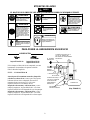
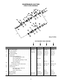
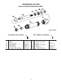
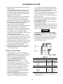
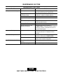
MAINTENANCE SECTION
9T WITH AUTOMATIC
SHUTOFF
(Dwg. TPB963)

14
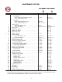
MAINTENANCE SECTION
PART NUMBER FOR ORDERING
9RS, 9S 9T
1 Motor Housing Assembly
Nonreversible
for 9S and 9T models ending in 53 or 83 . . . . . . . . . . 9SL–A40 9TL–A40
for 9T models ending in –EU . . . . . . . . . . . . . . . . . . . ––– 9TL–EU–A40
Reversible
for 9R models ending in 53 or 83 . . . . . . . . . . . . . . . . 9RSL–A40 –––
for 9R models ending in –EU . . . . . . . . . . . . . . . . . . . 9RSL–EU–A40 –––
* Warning Label
for models ending in –EU . . . . . . . . . . . . . . . . . . . . . . EU–99 EU–99
* for all other models . . . . . . . . . . . . . . . . . . . . . . . . . . . WARNING–9–99 WARNING–9–99
2 Shutoff Valve . . . . . . . . . . . . . . . . . . . . . . . . . . . . . . . . . . . . . ––– 8TL–172
2A Shutoff Valve Body . . . . . . . . . . . . . . . . . . . . . . . . . . . . . . . . ––– 8TL–170
3 Shutoff Valve Spring . . . . . . . . . . . . . . . . . . . . . . . . . . . . . . . ––– 8TL–171
3A Shutoff Valve Stop . . . . . . . . . . . . . . . . . . . . . . . . . . . . . . . . . ––– 8TL–176
• 4 Exhaust Silencer . . . . . . . . . . . . . . . . . . . . . . . . . . . . . . . . . . 9SL–311 9SL–311
• 5 Exhaust Deflector
for models ending in –EU . . . . . . . . . . . . . . . . . . . . . . 9SL–EU–23 9SL–EU–23
for all other models . . . . . . . . . . . . . . . . . . . . . . . . . . . 9SL–23 9SL–23
• 6 Exhaust Deflector Seal (2) . . . . . . . . . . . . . . . . . . . . . . . . . . . WBT180N–103 WBT180N–103
7 Deflector Retaining Ring . . . . . . . . . . . . . . . . . . . . . . . . . . . . 9SL–203 9SL–203
8 Throttle Valve Plunger Assembly . . . . . . . . . . . . . . . . . . . . . 8SL–A302 8SL–A302
• 9 Throttle Plunger Seal . . . . . . . . . . . . . . . . . . . . . . . . . . . . 8SL–259 8SL–259
10 Throttle Plunger Bushing Assembly . . . . . . . . . . . . . . . . . . . 8SL–A503 8SL–A503
• 11 Throttle Plunger Bushing Seal . . . . . . . . . . . . . . . . . . . . . 405–159 405–159
12 Throttle Valve Plunger Stop . . . . . . . . . . . . . . . . . . . . . . . . . 8SL–305 8SL–305
13 Throttle Valve Seat Assembly . . . . . . . . . . . . . . . . . . . . . . . . 8SL–A303 8SL–A303
• 14 Valve Seat Face . . . . . . . . . . . . . . . . . . . . . . . . . . . . . . . . 8SL–159 8SL–159
• 15 Valve Seat Seal . . . . . . . . . . . . . . . . . . . . . . . . . . . . . . . . AF120–290 AF120–290
16 Throttle Valve Ball . . . . . . . . . . . . . . . . . . . . . . . . . . . . . . . . K6U–941 K6U–941
17 Throttle Valve Spring . . . . . . . . . . . . . . . . . . . . . . . . . . . . . . . 8SL–262 8SL–262
18 Regulator Body Assembly . . . . . . . . . . . . . . . . . . . . . . . . . . . ––– 8TL–A173
19 Regulator Spring . . . . . . . . . . . . . . . . . . . . . . . . . . . . . . . ––– 8TL–180
20 Regulator Ball . . . . . . . . . . . . . . . . . . . . . . . . . . . . . . . . . ––– 2U–722
21 Regulator Adjusting Screw . . . . . . . . . . . . . . . . . . . . . . . ––– 8TL–174
22 Lock Screw . . . . . . . . . . . . . . . . . . . . . . . . . . . . . . . . . . . ––– 8TL–179
23 Bleed Adjusting Screw . . . . . . . . . . . . . . . . . . . . . . . . . . ––– 8TL–175
24 Sensor Port Plug . . . . . . . . . . . . . . . . . . . . . . . . . . . . . . . . ––– 5081T–266
25 Regulator Body Cap . . . . . . . . . . . . . . . . . . . . . . . . . . . . ––– 8TL–181
26 Regulator Body Seal . . . . . . . . . . . . . . . . . . . . . . . . . . . . . . . ––– C321–606
27 Air Strainer . . . . . . . . . . . . . . . . . . . . . . . . . . . . . . . . . . . . . . 834–61 834–61
28 Inlet Bushing . . . . . . . . . . . . . . . . . . . . . . . . . . . . . . . . . . . . . 88V60–38 88V60–38
29 Throttle Lever . . . . . . . . . . . . . . . . . . . . . . . . . . . . . . . . . . . . 8SL–273 8SL–273
• 30 Throttle Lever Retaining Pin . . . . . . . . . . . . . . . . . . . . . . . . . MR–100 MR–100
* Not illustrated.
• To keep downtime to a minimum, it is desirable to have on hand certain repair parts. We recommend that you stock
one (pair or set) of each part indicated by a bullet (•) for every four tools in service.

15
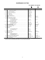
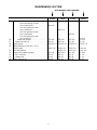
MAINTENANCE SECTION
PART NUMBER FOR ORDERING
9RS, 9S 9T
31 Reverse Valve Assembly . . . . . . . . . . . . . . . . . . . . . . . . . . . . . . . . 8RSL–A329 –––
• 32 Reverse Valve Seal (2) . . . . . . . . . . . . . . . . . . . . . . . . . . . . . . . 85H–167 –––
33 Reverse Valve Knob . . . . . . . . . . . . . . . . . . . . . . . . . . . . . . . . . . . 8RSL–163 –––
• 34 Reverse Valve Knob Pin . . . . . . . . . . . . . . . . . . . . . . . . . . . . . . . . R100B–120 –––
• 35 Detent Ball . . . . . . . . . . . . . . . . . . . . . . . . . . . . . . . . . . . . . . . . . . . 8RSL–31 –––
• 36 Detent Spring . . . . . . . . . . . . . . . . . . . . . . . . . . . . . . . . . . . . . . . . . 5RA–664 –––
37 Detent Adjusting Screw . . . . . . . . . . . . . . . . . . . . . . . . . . . . . . . . . . . . 8RSL–662 –––
38 Rotor . . . . . . . . . . . . . . . . . . . . . . . . . . . . . . . . . . . . . . . . . . . . . . . . . . 9SM–53 9SM–53
• 39 Vane Packet (set of 5 Vanes) . . . . . . . . . . . . . . . . . . . . . . . . . . . . . . . . 9SL–42–5 9SL–42–5
40 Rear Rotor Bearing Support
for Nonreversible Sizes . . . . . . . . . . . . . . . . . . . . . . . . . . . 9SL–25 9SL–25
for Reversible Sizes . . . . . . . . . . . . . . . . . . . . . . . . . . . . . . 9RSL–25 –––
• 41 Rear Bearing Support Gasket
for Nonreversible Sizes . . . . . . . . . . . . . . . . . . . . . . . . . . . 9SL–283 9SL–283
for Reversible Sizes . . . . . . . . . . . . . . . . . . . . . . . . . . . . . . 9RSL–283 –––
• 42 Rear Rotor Bearing . . . . . . . . . . . . . . . . . . . . . . . . . . . . . . . . . . . . . . . AG210–24Z AG210–24Z
• 43 Rotor Bearing Retaining Nut . . . . . . . . . . . . . . . . . . . . . . . . . . . . . . . . 8SL–118 8SL–118
44 Rear End Plate Gasket . . . . . . . . . . . . . . . . . . . . . . . . . . . . . . . . . . . . . 9SL–739 9SL–739
• 45 Rear End Plate . . . . . . . . . . . . . . . . . . . . . . . . . . . . . . . . . . . . . . . . . . . 9SL–12 9SL–12
46 Cylinder
for Nonreversible Sizes . . . . . . . . . . . . . . . . . . . . . . . . . . . 9SL–3 9SL–3
for Reversible Sizes . . . . . . . . . . . . . . . . . . . . . . . . . . . . . . 9RSL–3 –––
• 47 Front End Plate . . . . . . . . . . . . . . . . . . . . . . . . . . . . . . . . . . . . . . . . . . 9SL–11 9SL–11
• 48 Front Rotor Bearing . . . . . . . . . . . . . . . . . . . . . . . . . . . . . . . . . . . . . . . WFS182–24 WFS182–24
49 Cylinder Dowel
for Nonreversible Sizes . . . . . . . . . . . . . . . . . . . . . . . . . . . 9SL–98 9SL–98
for Reversible Sizes . . . . . . . . . . . . . . . . . . . . . . . . . . . . . . 9RSL–98 –––
50 Front Rotor Bearing Support Assembly . . . . . . . . . . . . . . . . . . . . . . . 9SL–A26 9SL–A26
51 Front Rotor Bearing Retainer . . . . . . . . . . . . . . . . . . . . . . . . . . . . AFH120A–362 AFH120A–362
52 Horizontal Hanger . . . . . . . . . . . . . . . . . . . . . . . . . . . . . . . . . . . . . . . . 9SL–366 9SL–366
• To keep downtime to a minimum, it is desirable to have on hand certain repair parts. We recommend that you stock
one (pair or set) of each part indicated by a bullet (•) for every four tools in service.

16
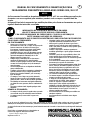
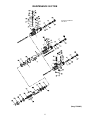
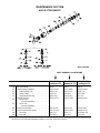
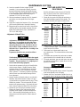
MAINTENANCE SECTION
GEAR CASE ASSEMBLY
(Dwg. TPC594)
PART NUMBER FOR ORDERING
M Ratio N Ratio P Ratio Q Ratio
75 Motor Clamp Washer . . . . . . . . . . . . . . . . . . . . . . . . 9SL–207 9SL–207 9SL–207 9SL–207
76 Gear Case Assembly . . . . . . . . . . . . . . . . . . . . . . . . 9SL–A37 9SN–A37 9SN–A37 9SN–A37
77 Grease Fitting . . . . . . . . . . . . . . . . . . . . . . . . . . . D0F9–879 D0F9–879 D0F9–879 D0F9–879
Gear Head Assembly . . . . . . . . . . . . . . . . . . . . . . . . ––– 9SN–A216 9SP–A216 9SQ–A216
78 Gear Head . . . . . . . . . . . . . . . . . . . . . . . . . . . . . ––– 9SN–216 9SP–216 9SQ–216
79 Planet Gear Assembly (3)
for N ratio gearing (15 teeth,
color–coded green) . . . . . . . . . . . . . . . . ––– 9SN–A9 ––– –––
for P and Q ratio gearing (17 teeth,
color–coded red) . . . . . . . . . . . . . . . . . . ––– ––– 9SP–A9 9SP–A9
80 Planet Gear Bearing
(2 for N ratio 1, for P and Q ratios) . . . . . . . ––– 8SL–500 WFS182–654 WFS182–654
81 Planet Gear Shaft (3) . . . . . . . . . . . . . . . . . . . . . ––– 8SN–190 8SL–191 8SL–191
82 Rotor Pinion
for N ratio (color–coded red) . . . . . . . . ––– 9SN–17 ––– –––
for P and Q ratio
(color–coded yellow) . . . . . . . . . . . . . . . ––– ––– 9SP–17 9SP–17
83 Gear Head Spacer . . . . . . . . . . . . . . . . . . . . . . . . . . ––– 9SN–80 9SN–80 9SN–80
Spindle Assembly . . . . . . . . . . . . . . . . . . . . . . . . . . 9SM–A108 9SN–A108 9SP–A108 9SQ–A108
84 Spindle . . . . . . . . . . . . . . . . . . . . . . . . . . . . . . . . 9SM–108 9SN–108 9SP–108 9SQ–108

17
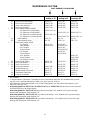
MAINTENANCE SECTION
PART NUMBER FOR ORDERING
M Ratio N Ratio P Ratio Q Ratio
85 Spindle Planet Gear Assembly (3)
for M ratio gearing (22 teeth,
color–coded yellow) . . . . . . . . . . . . . . . 9SM–A10 ––– ––– –––
for N ratio gearing (15 teeth,
color–coded steel) . . . . . . . . . . . . . . . . . ––– 9SN–A10 ––– –––
for P ratio gearing (16 teeth,
color–coded green) . . . . . . . . . . . . . . . . ––– ––– 9SP–A10 –––
for Q ratio gearing (19 teeth,
color–coded red) . . . . . . . . . . . . . . . . . . ––– ––– ––– 9SQ–A10
86 Planet Gear Bearing . . . . . . . . . . . . . . . . . . . W22–654 9SN–500 W22–654 W22–654
87 Planet Gear Shaft (3) . . . . . . . . . . . . . . . . . . . . . 9SL–191 9SN–190 9SL–191 9SL–191
88 Spindle Spacer . . . . . . . . . . . . . . . . . . . . . . . . . . . . . WFS182–111 WFS182–111 WFS182–111 WFS182–111
89 Spindle Bearing (2 for M ratio; 1 for N,
P and Q ratios) . . . . . . . . . . . . . . . . . . . . . . . . . . . . . R1602–510 R1602–510 R1602–510 R1602–510
90 Gear Head Bearing . . . . . . . . . . . . . . . . . . . . . . . . . ––– R1602–510 R1602–510 R1602–510
91 Reaction Bar Adapter Assembly . . . . . . . . . . . . . . . 9SL–A60 9SL–A60 9SL–A60 9SL–A60
92 Bar Lock Screw . . . . . . . . . . . . . . . . . . . . . . . . . 9SL–50 9SL–50 9SL–50 9SL–50
93 Adapter Bolt . . . . . . . . . . . . . . . . . . . . . . . . . . . . 9SL–49 9SL–49 9SL–49 9SL–49
94 Torque Reaction Bar . . . . . . . . . . . . . . . . . . . . . . . . 9SL–48 9SL–48 9SL–48 9SL–48

18
MAINTENANCE SECTION
ANGLE ATTACHMENTS
(Dwg. TPC595)
PART NUMBER FOR ORDERING
For Models
ending in 32
For Models
ending in 53
For Models
ending in 83
100 Angle Attachment . . . . . . . . . . . . . . . . . . . . . . . 8SA32 8SA53 9SA83
100 Angle Housing Assembly . . . . . . . . . . . . . . . . 8SA32–A550 8SA53–A600 182A83–A600
101 Angle Housing Cap . . . . . . . . . . . . . . . . . 8SA32–110 182A53–110 R00B–110
102 Grease Fitting . . . . . . . . . . . . . . . . . . . . . . D0F9–879 D0F9–879 D0F9–879
• 103 Upper Spindle Bearing . . . . . . . . . . . . . . . 8SA32–603 182A53–603 34U–367
• Matched Gear Set . . . . . . . . . . . . . . . . . . . . . . 8SA32–A552 182A53–A602 182A83–A602
104 Bevel Pinion
(not sold separately) . . . . . . . . . . . . . . ––– ––– –––
105 Bevel Gear
(not sold separately) . . . . . . . . . . . . . . ––– ––– –––
• 106 Bevel Pinion Bearing . . . . . . . . . . . . . . . . . . . 182A53–606 182A53–606 182A83–606
107 Bevel Pinion Bearing Spacer . . . . . . . . . . . . . 182A53–A165 182A53–A165 182A83–A165
108 Front Seal . . . . . . . . . . . . . . . . . . . . . . . . . R18LF–21 R18LF–21 AFH120A–358
109 Rear Seal . . . . . . . . . . . . . . . . . . . . . . . . . . C321–606 C321–606 C321–606
• To keep downtime to a minimum, it is desirable to have on hand certain repair parts. We recommend that you stock
one (pair or set of each part indicated by a bullet (•) for every four tools in service.

19
MAINTENANCE SECTION
PART NUMBER FOR ORDERING
For Models
ending in 32
For Models
ending in 53
For Models
ending in 83
110 Bevel Pinion Thrust Bearing . . . . . . . . . . . . . . R1610–105 R1610–105 R1610–105
111 Bevel Pinion Thrust Washer . . . . . . . . . . . . . . . 182A53–554 182A53–554 182A53–554
112 Bevel Pinion Snap Ring . . . . . . . . . . . . . . . . . 182A53–689 182A53–689 182A53–689
113 Bevel Pinion Retainer . . . . . . . . . . . . . . . . . . . . 182A53–589 182A53–589 182A53–589
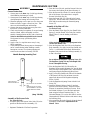
◊ 114 Socket Adapter Spindle Assembly
3/8” Square Drive (flush spindle) . . . . . 8SA32–P507–3/8 ––– –––
+ 1/2” Square Drive (flush spindle) . . . . . ––– 182A53–P507–1/2 182A83–P507–1/2
+ 3/8” Square Drive (recessed spindle) . . 8SA32–P607–3/8 ––– –––
+ 1/2” Square Drive (recessed spindle) . . ––– 182A53–A607–1/2 182A83–A607–1/2
115 Socket Retainer . . . . . . . . . . . . . . . . . . . . . . 5020–716 804–716 804–716
116 Socket Retainer Spring . . . . . . . . . . . . . . . . 401–718 5UHD–718 5UHD–718
◊ * Flush Socket Adapter Spindle
1/2” Hexagon . . . . . . . . . . . . . . . . . . . . 8SA34–807 182A54–807 –––
13mm Hexagon . . . . . . . . . . . . . . . . . . . 8SA34–807M 182A13MF–807 –––
9/16” Hexagon . . . . . . . . . . . . . . . . . . . ––– 182A55–807 –––
15 mm Hexagon . . . . . . . . . . . . . . . . . . ––– 182A15MF–807 –––
5/8” Hexagon . . . . . . . . . . . . . . . . . . . . ––– 182A56–807 –––
17 mm Hexagon . . . . . . . . . . . . . . . . . . ––– 8SA56–807M –––
11/16” Hexagon . . . . . . . . . . . . . . . . . . ––– ––– 182A87–807
18 mm Hexagon . . . . . . . . . . . . . . . . . . ––– ––– 9SA87–807M
3/4” Hexagon (19 mm) . . . . . . . . . . . . . ––– ––– 182A88–807
• 118 Lower Spindle Bearing . . . . . . . . . . . . . . . . . . . 8SA32–593 182A53–593 182A83–593
◊ 119 Bevel Gear Retainer . . . . . . . . . . . . . . . . . . . . . 8SA32–578 ––– –––
◊ 120 Bevel Gear Lock Nut . . . . . . . . . . . . . . . . . . . . ––– 182A53–578 182A83–578
121 Bevel Spacer Retainer . . . . . . . . . . . . . . . . . . . 182A53–685 182A53–685 182A53–685
122 Spindle Bearing Cap . . . . . . . . . . . . . . . . . . . . . 8SA32–531 182A53–531 182A83–531
* Spindle Bearing Cap Wrench . . . . . . . . . . . . . . 8SA32–26 WFS182–26 WFS182–26
124 Attachment Coupling Nut . . . . . . . . . . . . . . . . 8SA32–27 8SA32–27 8SA32–27
125 Coupling Nut Retainer . . . . . . . . . . . . . . . . . . . 182A53–29 182A53–29 182A53–29
* Not illustrated.
• To keep downtime to a minimum, it is desirable to have on hand certain repair parts. We recommend that you stock
one (pair or set of each part indicated by a bullet (•) for every four tools in service.
◊ When ordering a Socket Adapter Spindle (114) or Flush Socket Spindle, also order a Bevel Gear Retainer (119) or
Bevel Gear Lock Nut (120).
+ When using Spindle No. 8SA32–P507–3/8, 182A53–P507–1/2, or 182A83–P507–1/2, the rear face of the socket will
be flush with the face of the Angle Housing.
When using Spindle No. 8SA32–P607–3/8, any socket not exceeding 15/16” diameter will fit up into the Angle
Housing, thus reducing the overall height by 1/4”.
When using Spindle No. 182A53–A607–1/2, any socket not exceeding 1–11/32” diameter will fit up into the Angle
Housing, thus reducing the overall height by 1/4”.
When using Spindle No. 182A83–A607–1/2, any socket not exceeding 1–7/16” diameter will fit up into the Angle
Housing, thus reducing the overall height by 1/4”.

20
MAINTENANCE SECTION
ANGLE HOUSING EXTENSION ASSEMBLY
(Dwg. TPC420)
PART NUMBER FOR ORDERING PART NUMBER FOR ORDERING
6” Angle Housing Extension 205 Extension Arbor Retainer 182A53–589
Assembly . . . . . . . . . . . . . . . . . . . . 8SL–A327–6 206 Extension Arbor Thrust
200 Extension Arbor . . . . . . . . . . . . 8SL–327–6 Bearing . . . . . . . . . . . . . . . . . . . R1610–105
201 Arbor Housing . . . . . . . . . . . . . 8SL–43–6 207 Extension Arbor Thrust
202 Arbor Spacer . . . . . . . . . . . . . . WFS182–111 Washer . . . . . . . . . . . . . . . . . . . 182A53–554
203 Arbor Bearing . . . . . . . . . . . . . R1602–510 208 Coupling Nut . . . . . . . . . . . . . . 8SA32–27
204 Extension Arbor Snap Ring . . . 182A53–689 209 Coupling Nut Retainer . . . . . . . 182A53–29
La page est en cours de chargement...
La page est en cours de chargement...
La page est en cours de chargement...
La page est en cours de chargement...
La page est en cours de chargement...
La page est en cours de chargement...
La page est en cours de chargement...
La page est en cours de chargement...
-
 1
1
-
 2
2
-
 3
3
-
 4
4
-
 5
5
-
 6
6
-
 7
7
-
 8
8
-
 9
9
-
 10
10
-
 11
11
-
 12
12
-
 13
13
-
 14
14
-
 15
15
-
 16
16
-
 17
17
-
 18
18
-
 19
19
-
 20
20
-
 21
21
-
 22
22
-
 23
23
-
 24
24
-
 25
25
-
 26
26
-
 27
27
-
 28
28


Ingersoll-Rand 9RSS Operation and Maintenance Manual
- Catégorie
- Outils électroportatifs
- Taper
- Operation and Maintenance Manual
dans d''autres langues
- English: Ingersoll-Rand 9RSS
Documents connexes
-
Ingersoll-Rand 7802S Operation and Maintenance Manual
-
-
-
-
-
-
-
-
-
Ingersoll-Rand 3RLO2S3-EU Instructions Manual