La page est en cours de chargement...

EEWB332B
MOTORIZED WHEEL
BALANCER
OPERATOR’S MANUAL
MANUEL OPÉRATEUR
MANUAL DE OPERADOR

ii
EEWB332B

3
EEWB332B
IMPORTANT SAFETY INSTRUCTIONS
• Basic sa
fety precau• ons should always be followed.
Wear safety goggles.
Read and follow all Instruc! ons and safety messages.
Wear appropriate clothing; keep hair and loose " # ng clothing, your hands
and all parts of your body away from moving parts.
Eye injury or other bodily injury can result from fl ying par• cles or entanglement with
moving parts.
• Electric powered wheel balancer can cause shocks, fi re or explosion.
Do not operate the wheel balancer with a damaged power cord or plug.
Do not use on wet surfaces, outdoors or expose the balancer to rain.
Unplug the power cord when the balancer is not in use.
If an extension cord is used, make sure that it is in good condi! on and that the cur-
rent ra! ng is 8 Amps or higher.
Use only in well ven! lated areas.
Do not operate the balancer in the vicinity of $ ammable liquids (gasoline) or below
grade or in an explosive atmosphere.
Electric shock, fi re or explosion can cause serious injury or death.
• Misuse of this wheel balancer can result in accidents.
Do not allow untrained or unauthorized personnel to operate the balancer.
Do not disable or bypass the hood safety interlock system.
Always securely ! ghten the quick nut that holds the wheel in place during the
moun! ng procedure.
Improperly balanced wheels can cause damage to the vehicle or automo• ve acci-
dents. Personal injury can result from altera• on to the balancer or improper use.

4
EEWB332B
TABLE OF CONTENTS
IMPOR
TANT SAFETY INSTRUCTIONS.......................................................................................3
1.0
INTRODUCTION
...........................................................................................................................
5
1.1 SAFETY NOTICE ..........................................................................................................................5
1.2 BALANCER APPLICATION ..........................................................................................................5
1.3 EEWB332B SPECIFICATIONS ...................................................................................................6
1.4 FEATURES ...................................................................................................................................6
1.5 STANDARD ACCESSORIES ........................................................................................................7
1.6 OPTIONAL ACCESSORIES .........................................................................................................7
1.7 DIMENSIONS OF THE MACHINE ................................................................................................8
1.8 REQUIRED INSTALLATION AREA ...............................................................................................8
1.9 INSTALLATION INSTRUCTIONS .................................................................................................8
2.0 BALANCER INSTALLATION ......................................................................................................... 9
2.1 ELECTRIC INSTALLATION ..........................................................................................................9
2.2 MONITOR FRAME INSTALLATION ............................................................................................10
2.3 INSTALLATION OF THE HOOD GUARD ...................................................................................10
3.0 TERMINOLOGY ..........................................................................................................................12
3.1 THE INPUT PANEL .....................................................................................................................12
4.0 OPERATION OF THE BALANCER .............................................................................................14
4.1 CHECK LIST - INSPECTION ......................................................................................................14
4.2 WHEEL MOUNTING ................................................................................................................... 15
4.2.1 STANDARD WHEELS (BACK CONE MOUNT) .........................................................................15
4.2.2 CENTERING LIGHT-TRUCK WHEELS .....................................................................................15
4.2.3 WHEEL MOUNTING REQUIRING SPECIAL TOOLING ............................................................16
4.3 MODE SELECTION ....................................................................................................................16
4.3.1 WEIGHT PLACEMENT MODES .................................................................................................16
4.3.2 SAPE ARM POSITIONS FOR ALU WEIGHTS PLACEMENT ....................................................17
4.4 SELECTING OPERATOR PREFERENCES ...............................................................................18
4.4.1 FINE BALANCING MODE ..........................................................................................................18
4.4.2 OUNCE/GRAMS CONVERSION ................................................................................................18
4.4.3 RIM DIAMETER IN MILLIMETERS ............................................................................................18
4.5 ENTER RIM PARAMETERS ......................................................................................................18
4.5.1 RIM DISTANCE AND DIAMETER (OFFSET) ............................................................................18
4.5.2 RIM WIDTH MEASUREMENT ................................................................................................... 18
4.5.3 MEASURE/ENTER RIM WIDTH (MANUAL) ............................................................................. 18
4.5.4 AUTOMATIC RIM DIMENSION AND ALU MODE ..................................................................... 19
4.6 Easy Alu FUNCTION ...................................................................................................................19
4.6.1 AUTOMATIC RIM DIMENSION AND ALU MODE ...................................................................... 19
4.7 CORRECTION OF THE IMBALANCE ........................................................................................20
4.7.1 USING THE LASER INDICATOR ...............................................................................................21
4.7.2 APPLYING WEIGHT WITH THE LASER POINTER ...................................................................21
5.0 ALU 2P and ALU 3P ....................................................................................................................22
6.0 SPOKE BALANCING MODE ......................................................................................................23
6.1 SPLIT WEIGHT MODE (SWM) ...................................................................................................23
7.0 USER CALIBRATION .................................................................................................................24
8.0 USER FUNCTIONS ....................................................................................................................25
8.1 DATA RECALL ............................................................................................................................25
8.2 WEIGHT UNIT TOGGLE MODE .................................................................................................26
8.3 DIMENSION UNIT TOGGLE MODE ...........................................................................................26
8.4 ANTI-SLIP FUNCTION................................................................................................................ 26
9.0 OPTIMIZATION/WEIGHT MINIMIZATION. .................................................................................27
10.0 TROUBLE SHOOTING ...............................................................................................................35
10.1 SYSTEM MESSAGES ................................................................................................................36
10.1.1 C CODES ....................................................................................................................................36
10.1.2 E-CODES ....................................................................................................................................38
10.1.3 H CODES - WARNING ...............................................................................................................40
11.0 MAINTENANCE ..........................................................................................................................41

5
EEWB332B
1.0 INTRODUCTION
Congratulations on purchasing the EEWB332B
motorized wheel balancer
.
This wheel balancer is designed
for ease of operation, accuracy, reliability and speed. With a minimum of maintenance and care your wheel
balancer will provide many years of trouble-free operation.
Instructions on use, maintenance and operational requirements of the machine are covered in this manual.
STORE THIS MANUAL IN A SAFE PLACE FOR FUTURE REFERENCE.
READ THIS MANUAL THOROUGHLY BEFORE USING THE MACHINE.
1.1 SAFETY NOTICE
This manual is a part of the balancer product.
Read carefully
all warnings and instructions of this manual since they provide important information concerning
safety and maintenance.
1.2 BALANCER APPLICATION
The Snap-on wheel balancer model EEWB332B is intended to be used as equipment to balance car and light
truck wheels within the following range:
Maximum wheel diameter : 42” (1067mm)
Maximum wheel width : 20” (508mm)
Maximum wheel weight : 154 lbs / 69.8 kg
This equipment is to be only used in the application for which it is specifi cally designed.
Any other use shall be considered as improper and abusive.
The manufacturer shall not be considered liable for possible damages caused by improper, wrong, or abusive
use of this equipment.

6
EEWB332B
1.3 EEWB332B SPECIFICATIONS
M
otorized digital wheel balancer for car, light truc
k
wheels.
W
eight Imbalance
Accuracy .10 oz. / 2.8 grams
Weight Placement Resolution ± .7 degrees
Weight Imbalance Resolution:
Roundoff Mode .25 oz. / 5 grams
Non-Roundoff Mode .05 oz. / 1 gram
Max. Shaft Weight Capacity 154 lbs / 69.8 kg
Max.Tire Diameter 42” / 1067 mm
Rim Width Capacity 3”-20” / 76 mm - 508 mm
Rim Diameter Capacity 8”-32” / 203 mm-812 mm
Balancing Cycle Time. 6-8 seconds
Shaft Speed at calculation 200 RPM
Electrical 115vac, 1ph, 60Hz, 4A
Required Work Area 100” x 67” (2540 x1702 mm)
Shipping Weight, complete 366 lbs (166 kg)
Shipping Dimensions 62” x 64” x 44”
Machine Dimensions (HxWxD) 70” x 59” x 45”
Actual Weight with Accessories 325 lbs / 147.4 kg
Operating Temperature Range 32-122F / 0-50C
1.4 FEATURES
ACCURACY
• Weight placement accuracy is ± .7°
• Weight imbalance accuracy to 2.8 grams.
• Self test check with every power up cycle.
• Fast operator calibration.
• Pre-programmed Error Codes indicate procedural
errors or safety concerns.
SPEED and DURABILITY
• Automatic distance and diameter entry. Simply
touch the SAPE arm to the wheel, the distance and
diameter parameters are automatically entered.
Width is automatically entered using a Sonar sonic
transducer.
• A pinpoint laser identifi es adhesive weight place-
ment location on rims.
• Quick clamp speed nut reduces wheel mounting
time.
• Captured back spring eliminates having to handle
the backing spring.
• Quick cycle time of 6 to 8 seconds
• Automatic recalculation if weight positions are
changed. No need for re-spinning the wheel.
• Common 40 mm diameter mounting shaft.
• Weight pocket storage tray.
• Easy-to-Read Data display.
• Easy weight tray access.
SOFTWARE VERSATILITY
• Both dual weight Dynamic and single weight Static
capability.
• Match Balance program for reducing weight re-
quired.
• Built-in spin counter for monitoring balancer pro-
ductivity.
• Service code access to all Balancer electronic
functions for fast, easy diagnosis.
• Operator selectable round-off mode.
• Easy Alu enter the rim dimensions and automati-
cally select a balancing mode.
• 5 Aluminum Modes
• 2 Alu-S modes
• Hidden Weight (Spoke) mode
• Ounce / Gram toggle from front panel
• Multiple operator feature allows several operators
to recall wheel parameters.

7
EEWB332B
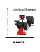
1.5 STANDARD
ACCESSORIES
Standard accessories ( Figures 1, 2, and 3,) included
with the EEWB332B are:
1
EAM0003J69A
Cone, 87-137 mm / 3.4”-5.4”
2 EAM0005D25A Cone, 96-114 mm / 3.8”-4.5”
3 EAM0005D24A Cone, 71-99mm /2.8”-3.9”
4 EAM0005D23A Cone, 40-76mm / 1.6” -3.0”
5 EAC0058D07A Cup -Pressure
6 EAC0058D08A Disk -Pressure
7 EAA0263G66A Quick Nut
8 EAM0005D40A Weight -Calibration
9 EAM0021D90A Standard 40mm Stub Shaft
10 EAA0247G21A Caliper -Rim Width
11 EAC0060G02A Flange -Cover, Hook
12 EAM0006G01A Pin -Accessory
13 WWPR13A Weight Pliers
14 EAM0005D34A Fastening Rod
15 EAC0058D15A Soft Protector Ring
Figure 3 - Plier
Figure 1
Figure 2 - Rim width gauge
1.6 OPTIONAL
ACCESSORIES
EEWB3-1A
Car, SUV and Lt Truck Pin Plate Set
EEWB3-5 Spacer EEWB3-4
9-pc Collet Set
EEWB3-1A Car, SUV and Lt Truck Pin Plate Set
EEWB3-4 9-pc Collet Set
EAK0309J20A Stand
Weight Pliers (Figure 3).
Ver
satile weight hammer/plier. In addition to hammering
on weight and used weight removal, the hammer/plier
can be used to reshape worn weight clips and trim
weight to size.

8
EEWB332B
PRE-INSTALLATION CONSIDERATIONS
1.7 DIMENSIONS OF THE MACHINE
Figure 5
- Recommended W
ork Area
1.9 INSTALLATION INSTRUCTIONS
CAUTION! CAREFULLY REMOVE THE BALANCER
FROM THE PALLET
.
Remove the hardware that secures the machine
to the pallet and slide the balancer onto the fl oor
where it is to be installed.
THE UNIT IS HEAVY AND THE WEIGHT IS NOT
EVENLY DISTRIBUTED.
DO NOT LIFT THE BALANCER BY THE SHAFT.
DROPPING THE UNIT MAY CAUSE PERSONAL
INJURY OR EQUIPMENT DAMAGE.
62”
36”
67”
Figure 4
- Actual Footprint Dimensions.
1.8 REQUIRED INSTALLATION AREA
Make sure that from the operating position the user
can see all of the machine and the surrounding area.
The operator
should prevent non authorized persons
and/or objects from entering the area which may create
potential hazards.
The machine should be installed on a stable level fl oor.
Do not install the machine on a uneven fl oor.
If the balancer is to be installed on a raised fl oor, the
fl oor must have a capacity of at least 110lbs per sq ft.
(5000 N/m² - 500 kg/m²).
It is not required to secure the machine to the fl oor.
Install the machine in a dry, covered area.
The installation of the machine requires a working area
of at least 100” x 67” (2540mm x 1702 mm) (Figure 5).
NOTE: Do not install the balancer below grade level
or in a pit.

9
EEWB332B
2.1 ELECTRIC INST
ALLATION
ANY ELE CT RICAL WIR ING MUS T BE
PERFORMED BY
LICENSED PERSONNEL.
ALL
SERVICE MUST BE PERFORMED BY AN
AUTHORIZED SERVICE TECHNICIAN.
Check on the plate of the machine that the electrical
specifi ca tions of the power source are the same as
the machine. The machine uses 115VAC, 60Hz, 1Ph,
6.0 Ampere.
NOTE:
Any electrical
outlet installation must be verifi ed
by a licensed electrician before connecting the
balancer.
NOTE:
This machine performs a self-test routine on start-
up. There will be a delay of several seconds before
the display is activated.
Figure 6
2.0 BALANCER INSTALLATION
Mounting the Shaft
Adapter
IMPORTANT!
CHECK THAT THE SURFACES ARE PERFECTLY
CLEAN AND NOT DAMAGED. AN INCORRECT
MOUNTING MAY RESULT IN SIGNIFICANT
IMBALANCE.
A. Mount the threaded shaft onto the arbor of the
balancer. Tighten fi rmly using supplied rod. (Figure 6).
Figure 7
C. Place cones and other accessories onto the
accessory pins.
B. Install
the accessory pins (Figure 7). Tighten fi rmly.

10
EEWB332B
2. Rotate tower 180º clockwise and reinstall the 3
bolts, see Figure 9.
Figure 9
Figure 10
2.2 MONITOR FRAME INSTALLATION
INSTRUCTIONS
The monitor
tower for the EEWB332B is shipped in-
verted so to facilitate shipping ease and to avoid dam-
age. Follow these instructions for the proper installation
procedures.
MONITOR TOWER INSTALLATION:
The Monitor Tower is shipped un-assembled to avoid
damage.
1. Remove 3 bolts (2 holding monitor tower) See
Figure 8.
Figure 8
2.3 INSTALLATION OF THE HOOD
GUARD
1. Slide the wheel guard onto the pivot tube and
raise it until the fastening holes of wheel guard
and wheel guard arbor align. See Figure 10
2. I
nsert two 3/8” bolts with washers into the holes,
install the hexagon nuts and washers and
tighten.

11
EEWB332B
Figure 11
Figure 12
3. Connect the plug of the cable with the connec-
tor of the machine which is projecting out of the
opening in the balancer cabinet. See Figure 1
1.
4. Place the harness loosely inside the machine
through the hole in the machine cabinet. See
Figure 12.
!!IMPORTANT!!!
Machines are shipped calibrated from the
factory. Do not attempt fi
eld calibration
unless balance results deem calibration
as necessary.

12
EEWB332B
3.0 TERMINOLOGY
Before
using the wheel balancer it is suggested that
you
become
familiar with the terminology and features
of the machine’s components. Refer to Figures from
13 to 14 for identifi cation and location.
Figure 13
Figure 13a
1
2
3
4
5
6
7
8
9
3.1
THE INPUT PANEL
INPUT PANEL - Figure 13a
1. Diameter key with indicator
Press to
select “rim diameter” mode. The diameter
indicator will light up, the unit will beep. The current
value will be shown on the display and can be edited.
2. Width key with indicator
Press to select “rim width” mode. The width indicator
will light up, the unit will beep. The current value will
be shown on the display and can be edited.
3. Offset key with indicator
Press to select “offset” mode. The offset indicator
will light up, the unit will beep. The current value will
be shown on the display and can be edited.
Pressing the offset key in HWM enables the operator
to enter the plane reference points again.
4. + key
To increase an input value (e.g. rim diameter, offset,
rim width).
Hold down to change the value shown automatically.
5. Enter key
Press to confi rm input (dimension, mode) or save
“user” settings. The unit will beep.
6. - key
To decrease an input value (e.g. rim width, offset,
rim diameter).
Hold down to change the value shown automatically.
7. MODE key with indicator
Press to scroll along the special modes. The MODE
key indicator will light up, the unit will beep.
8. Fine key
Press to toggle the read-out accuracy between
0,25 resp. 0,05 oz. (5 and 1 grams). The unit will
beep. Combined with the “MODE” key, it starts the
calibration function.
9. Weight key
Press to select the required weight application mode
(weight mode), the unit will beep. Combined with the
“MODE” key, it starts the “user” function.
Note: If pressed for at least three seconds, it recalls
directly the Normal mode (Clip-Clip) and reduces the
number of ALU modes that can be selected “Quick
ALU Mode”.
10.Stop key
Press to stop a spinning wheel.
10
USER INTERFACE - Figure 13
1. Position Indicator LEDs - Displays the location for
wheel weight placement.
2.
Inside Weight Amount and Function Display
Window Shows inside or left weight amount and
various operation messages.
3. Outside Weight Amount and Function Display
Window Shows outside or right weight amount and
various operation messages.
4. Function Indicator LEDs - indicating active functions
and weights placement positions. They allow to set
the proper workfl ow.
5. Input panel - it allow the main user selections.
1
2
3
4
5

13
EEWB332B
Figure 14
12
13
14
15
16
19
20
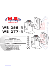
CABINET - Figure 14
12.
Display - Easy to read, user friendly display
featuring large LEDs and one button functions.
13. Weight Storage Tray - Generous storage for a
variety of weight profi les and sizes as well as built
in storage pockets for the standard centering cones.
14. Accessory Storage - Four sturdy side mounted pegs
are supplied for storage of additional accessories.
15. Wheel Guard Assembly.
16. Semi-Automatic Parameter Arm - Rim distance
and diameter is automatically input with the SAPE.
The SAPE is also used in several procedures for
determining accurate rim profi les and tape weight
placement.
17. Foot Operated Shaft Lock -A foot operated shaft
lock is used to stabilize the shaft during the weight
placement process.
18. Laser weight placement indicator.
19. Shaft Adapter - A common 40 mm size shaft is
used. The easily removable shaft can be replaced
for service or during use of certain wheel adapters
20. Sonic Transducer - Used for detection of the rim
width.
18
17
1
2
Figure 14a
Figure 14b
MAIN SHAFT LOCK - Fig. 14a
Pedal of main shaft lock
The main
shaft is locked when the pedal is depressed.
This also facilitates tightening or loosening of the
clamping nut.
Note:
This lock is designed only to facilitate orientation
of the wheel and must not be used for braking the
main shaft spin.
SAPE PARAMETER ARM - Fig. 14b
SAPE arm for distance and rim diameter.
1 SAPE
arm, can be extended and hinged upwards.
2 SAPE disk to identify rrim dimensions on all types
of RIM profi les.

14
EEWB332B
SONIC TRANSDUCER - Fig. 14c
On the outer side of the rim the machine has a Sonar
sensor to measure wheel width (outside of rim) .
The sonar has a tolerance of +/- 0.5’
’.
Figure 14c
Figure 14d
4.0 OPERATION OF THE BALANCER
WARNING: For operator safety please
read and follow the precautions outlined
on pages 1 and 2 of this manual.
NOTE: Read all instructions before pro-
ceeding with operation of the balancer.
All balancer functions are input into the main computer
through
the large easy to read touch panel. Although
each wheel tire assembly differ in some ways all bal-
ancing jobs require basically the same procedure. The
order of events to take place are:
1. Inspection of the wheel/tire assembly
2. Mounting wheel onto shaft or adapter
3. Selection of Balancing Mode and Preferences
4. Entry of wheel parameters
5. Spinning the wheel
6. Applying the recommended weight
7. Check spin if desired
8. Dismounting the wheel
The following operation instructions will follow the basic
outline above.
4.1 CHECK LIST - INSPECTION
Observe Before Balancing Wheel
1. Check
for proper air pressure. If not correct, infl ate
to correct pressure.
2. Check for any foreign material inside tire. If present,
remove before balancing tire.
WATER IS FOREIGN MATERIAL!
3. Remove old weights — old weights may be improper
value or in wrong location.
4. Be sure tire and wheel are free of excessive dirt,
rust and large stones. Use wire brush on back side of
wheel if necessary.
LASER INDICATOR - Fig. 14d
The machine uses the Laser weight placement indicator
to indicate a precise point for placing adhesive weights
on the rim.

15
EEWB332B
4.2
WHEEL MOUNTING
Nearly all standard wheels and many alloy wheels have
accurately machined center holes, and they should be
mounted with center cones. Accurate balancing depends
on accurate mounting of the wheel and correct seating of
the cone in the pilot hole. Insure that the wheel is centered
on the shaft exactly as it will be mounted to the vehicle.
Before starting any balancing procedure it is very
important that the wheel is mounted on the machine
with the proper adap tors. An incorrect centering of the
wheel will result in considerable imbalance.
There are many types of wheels and Snap-on supplies
adaptors of good quality and durability for the large
majority. However if you meet special wheels which may
require a specifi c adaptor, call your Snap-on distributor.
Rims may be divided into these major groups:
1. Car rims with a true center hole.
2. Car rims without a center hole.
3. Car rims with an untrue center hole.
4. Light truck rims.
5. Lug centric wheels
6. Clad wheels
4.2.1 STANDARD WHEELS (BACK CONE
MOUNT)
Mount the wheel as detailed below in Figure 15
Figure 15
1. Mount proper cone against spring plate.
2.
Mount wheel on shaft in the same manner as you
would on the car.
3. Mount pressure cup on shaft and place against
outside of wheel, follow with the Quick-nut.
4. Tighten Quick-nut securely with both hands. To
operate the Quick-nut pull the lock-unlock lever
(Figure 16). Slide the Quick-nut on the threaded
shaft. When in contact with the rim, release the
unlock lever and tighten fi rmly. To assist in cen-
tering the wheel properly, rotate the wheel on the
shaft while tightening the quick nut.
FAILURE TO TIGHTEN WING NUT SECURELY
MAY RESULT IN SERIOUS PERSONAL INJURY.
DO NOT USE A HAMMER TO TIGHTEN THE
QUICK NUT.
TO RELEASE THE QUICK NUT, UNSCREW
A FEW TURNS TO REDUCE THE AXIAL
PRESSURE, THEN PRESS THE UNLOCK
LEVER AND SLIDE AWAY FROM THE SHAFT.
5. Check that the wheel rotates true by turning the wheel
several revolutions while noting any excessive runout.
4.2.2 CENTERING LIGHT-TRUCK
WHEELS
An optional offset spacer may be required for some
light truck wheels and reverse-offset wheels that must
be moved away from the balancer mounting fl ange.
The extension adaptor is often used with the 5-1/4 inch
diameter light truck cone. (p/n EEWB-5)
Install the spacer on the mounting fl ange, then mount
the wheel, using the front cone method (Figure 17)
)
Figure 17
!
Figure 16

16
EEWB332B
4.2.3 WHEEL
MOUNTING REQUIRING
SPECIAL
T
OOLING
Clad wheels: A Clad Wheel is a wheel casting that is
balanced but the wheel face is not fi nished. To fi nish
the wheel face a plastic chromed face is bonded to
the casting.
A clad wheel must be centered properly from the back
side
of the wheel using precision collets instead of a
centering cone. A precision collet is normally a dual
sided centering device with low tapers on each side
and has a length of approximately 1.5 inches.
The benefi t of a precision collet is it fi ts very precisely
into the tapered machining on the back side of a cast
wheel and the collet does not protrude into the wheel
center. A cone also offers precision centering, but a
cone can have a length from the long to short end of
the taper of two inches or more. A taper cone unlike a
precision collet, will intrude into the wheel center.
On many clad wheels there are plastic tabs to hold the
cosmetic cover in place. It is also necessary to use a
pin plate in the front of the wheel.
The standard pressure cup may crack the plastic clad-
ding.
A centering cone can break off the tabs. See section
1.6 Optional Accessories for tooling recommendations.
4.3 MODE SELECTION
The majority of balancing takes place in the default
2-plane dynamic
mode which is displayed as “2 PL”
(location 1). Hammer-on clip weights will be placed
on both inside and outside of the rim edge. If required,
select an optional weight placement mode by pressing
the Mode button until the appropriate placement mode
is displayed.
4.3.1 WEIGHT PLACEMENT MODES
Before Spinning the wheel (although it may be done
af
terwards) choose the appropriate balancing mode
for the wheel. To select the various placement modes
press the (9) Weight Placement button;
until placement LEDs indicate desired placement
position.
A
. DYNAMIC (two planes), suggested for all steel rims.
In this case the wheel weights must be clipped onto the
rim edges. This function is selected as a default and
the LEDs corresponding to the wheel weight location
are lit on (Figure 19)
Figure 19
B.
STATIC (single plane - Figure 20). Suggested for
narrow rims (3” or less). Use a single corrective weight
placed in the center of rim as illustrated in Figure 20.
Figure 20
T
o select the STATIC Mode:
1. Touch the SAPE arm to the rim fl ange.
2. Enter the rim width dimension.
3. Press four times Alu button (9).
WEIGHT COMBINATION MODES USING THE
WEIGHT SELECTION BUTTON
See (Figure 21). Pressing the weight selection button
(9) will toggle the LED’s to the weight default selections
as shown. Balancing using a combination of hammer-on
and adhesive weights as shown in Figure 21.
Figure 21
9

17
EEWB332B
4.3.2 SAPE ARM POSITIONS FOR ALU
WEIGHTS PLACEMENT
Fig.
22 shows the corrected reading positions of the
SAPE arm (1), depending on the required weight
positions (2); adhesive weights and clip-on weights.
Weight Placement illuminated indicators indicate the
weights placement positions on the rim.
— = SAPE arm application point (1).
= resulting in weight position (2).
Normal
Touch the SAPE arm to the rim fl ange (a).
Manually input the rim width dimension. This
mode require the clip-on weights placement.
Alu 1 Touch the SAPE arm to the rim fl ange (a).
Manually input the rim width dimension. Press
once the Alu key (9). This mode uses the
standardized adhesive weights placement.
Alu 2 Touch the SAPE arm to the rim fl ange (a).
Manually input the rim width dimension. Press
twice the Alu key (9). This mode uses the
standardized adhesive weights placement.
Alu 3 Touch the SAPE arm to the rim fl ange (a).
Manually input the rim width dimension. Press
three times the Alu key (9). This mode uses
the standardized weights placement
.
Alu 4
Touch the SAPE arm to the rim fl ange (a).
Manually input the rim width dimension. Press
six times on the Alu key (9). This mode uses
the standardized weights placement.
Alu 5 Touch the SAPE arm to the rim fl ange (a)
.
Manually input the rim width dimension. Press
seven times on the Alu key (9). This mode uses
the standardized weights placement.
Alu 1P Touch the SAPE arm to the rim fl ange (b). Press
once the Easy Alu Toggle key (9).
Manually input the rim width dimension.
- The internal correction plane for adhesive
weights is precisely indicated by the machine.
Note: Make sure all entries are completed prior to
balancing spin.
Alu 2P Perform the SAPE arm detection in (b-c) points.
- The adhesive weights are placed where the
readings are taken, according to the reading
positions.
Alu 3P Perform the SAPE arm detection in (a-c) points.
- The adhesive weight is placed where the
reading is taken, according to the reading
position.
Note: The Easy Alu Toggle key (6), can retrieve an
alternative ALU P mode.
9
Figure 22

18
EEWB332B
4.4 SELECTING OPERA
TOR PREFERENCES
4.4.1 FINE BALANCING MODE
This
balancer
measures with the maximum precision
availa ble all the time, 1g / 0.05 oz, however values
below 5g / 0.25 oz are shown as zero while in the
normal operating mode. Values exceeding 5g / 0.25 oz
are rounded to the amount of the nearest commercial
wheel weight.
Press the FINE button to advance to the display
resolution between 5g / 0.25 oz and 1g / 0.05 oz.
4.4.2 OUNCE/GRAMS CONVERSION
When the machine is fi rst turned on it is preset to d
isplay
the imbalance in ounces.
Press the MODE button to advance to select ounces
or grams.
Select Enter to save selection.
4.4.3 RIM DIAMETER IN MILLIMETERS
The rim diameter is normally displayed in inches,
however if the value in millimeters is desired. Press
the MODE button until “PAX/mm” is NOT illuminated
to display in inches, when lit the unit displays in mm.
4.5 ENTER RIM PARAMETERS
4.
5.1 Rim Distance and Diameter (offset) - Move
the rim offset arm to the edge of the rim, touch the
pointer to the rim edge as illustrated in Figure 23a
and hold steady for about a second. The beeper
will sound when the distance and diameter values
are calculated and entered. Return the arm to its
fully in and down position on the balancer. Do not
allow the measurement arm to “dangle” down in
front of the balance.
.
Figure 23a
4.5.2
- Rim Width Measurement - Lower the hood
guard. The rim width will be automatically enter
using the sonar sonic device mounted on the hood
guard frame.
4.5.3. Measure/Enter rim width (manual) using
rim width
calipers. Measure wheel where correc-
tive clip-on weight would be applied, Figure 23b.
Press the Width entry key, Figure 23a, and enter
the measured width by pressing +/- keys until the
desired value appears in the display.
Figure 23b
W
Figure 23

19
EEWB332B
4.5.4 Manual Parameter Entry
In
the
event of automatic gauge failure, the param-
eter values can be input manually. See manual
entry of rim width in the previous paragraph.
D
W
O
Figure 24a
Figure 24b
Figure 24c
4.5.4.1 Manual
Rim Diameter Entry - Select the
Manual Diameter button. Read the rim diameter
marked on the sidewall of the tire (Figure 24a and
24b). Press the Diameter Button (D) and enter the
measured rim diameter by selecting the +/- keys
until the desired value appears in the display.
4.5.4.2 Manual Distance Entry - Move the distance
gauge arm to touch the inner edge of the wheel
where weights are to be placed and observe the
reading on the scale of the distance gauge. See
Figure 24c. Press manual Wheel Offset button
(O) followed by selecting the +/- keys until value
is displayed in the display window.
NOTE: The parameter arm must be in the Home
rest position when the balancer is powered up.
This establishes the arm starting position.
Figure 25
4.6 Easy Alu FUNCTION
T
he Easy Alu function automatically recognizes the
desired weight location by placing the SAPE arm in
the correct locations.
Note:
Alu 4 and Alu 5 are not included in the Easy Alu
function. They require manual setting by the operator.
4.6.1 Automatic rim dimension reading
and setting and Alu Mode
Preparations:
— Compensation run carried out, if necessary.
— Wheel correctly clamped.
Important: The OK indication and recommendation
for optimization, as well as the optimization procedure
itself, will only be accurate if the rim width is correctly
entered (Sonic sensor or Manual Input).
Automatic rim distance and diameter reading with
an internal gauge arm
— Move the internal gauge arm into position on the
rim to select the initial weight application position
(internal rim side). Keep it in this position until an
audible signal is heard.
Only for Alu2P and Alu3P (Fig. 25):
— Position and hold the internal gauge in the
second position on the rim to select the
application position on the right side of the rim.
Shortly afterwards the machine emits an audible
signal to indicate that the machine automatically
saves the weight application coordinates.
— Move the gauge to the idle position.
— For Alu2P and Alu3P you can start the spin.
—
For all the other Alu, previously enter the rim Width.
At this point you can change the Alu mode suggested
by the machine, using the “Easy Alu Toggle” function.
Do this by pressing the key once.

20
EEWB332B
4.7 CORRECTION OF THE IMBALANCE
Th
e following weight types and application methods
are available:
•
Clip-on weights: Always apply by hand
• Stick-on weights: Can be applied by hand or using
the gauge head for the Alu 2P, Alu 3P or easy
weight mode.
A
B
Figure 26
H
and applied weights MUST be applied exactly
perpendicular to the shaft (12 o’clock position). After
Spinning the wheel look at the rotation indicators for
the left plane of the wheel, Figure 26-A. As the correct
Wheel Angle Position (WAP) gets closer more indicators
light up. When all the indicators are ON, the WAP
indicator will also light up, Figure 26-B. Follow same
procedure for placing weight in the right plane.
Note: When the correct angle is reached, all the rotation
indicators should be ON. If the wheel has been pushed
too far, only the indicators of the other half will come
ON. If this happens, the wheel must be slowly turned in
the opposite direction until the WAP position is reached.
The weight amount to be applied in that plane is shown
on the display.
Figure 26a
Figure 26a
Attaching a stick-on weight.
AL
U or STATIC weight modes only: Refer to Figure 26b.
Apply the weight on the rim in the 12 o’clock position,
always by hand.
Note: With STATIC weight modes, always apply the
weight at the rim center line. If not possible, split the
weights evenly and apply on another surface of the rim
(symmetrical to the rim center line).
Attaching a clip-on weight.
Refer to Figure 26a. Clip-on weights must always be
applied in the 12 o’clock position. The lip should rest
on the rim edge. Use the weight pliers to position it. In
STATIC mode only the left hand display is used.
/