
SWB 100
WHEEL BALANCER
EQUILIBREUSE DE ROUES
RADAUSWUCHTMASCHINE
•OPERATOR’S MANUAL
•NOTICE D’ UTILISATION
•BETRIEBSANLEITUNG

ii
Snap-on Equipment Srl a unico socio
Via Provinciale per Carpi, 33
42015 CORREGGIO (RE) ITALY
Tel.: +39-(0)522-733480
Fax: +39-(0)522-733479
E-mail: [email protected]
Internet: http://www.snapon-equipment.eu
EC DECLARATION (Original document contained in Spare Parts Booklet)
DECLARATION CE (Le document original fi gurant dans le Liste des pièces détachées)
CE KONFORMITÄTSERKLÄRUNG (Originaldokument in der Ersatzteilliste enthaltenen)
ДЕКЛАРАЦИЯ EC (Оригинал документа прилагается к ведомости запчастей)
DICHIARAZIONE CE (Originale contenuta nel Libretto Ricambi)
DECLARACIÓN CE (El original se encuentra en tabla de repuestos)
DECLARAÇÃO CE (O original está contida em Lista de peças)
- FACSIMILE -
- ФАКСИМИЛЕ -
ENG - DECLARATION OF CE CONFORMITY
FRA - DECLARATION CE DE CONFORMITE
DEU - KONFORMITÄTSERKLÄRUNG
FIN - EY-VAATIMUSTENMUKAISUUSVAKUUTUS
NLD - VERKLARING VAN OVEREENSTEMMING
SWE - EG-FÖRSÄKRAN OM ÖVERENSSTÄMMELSE
DAN - EF-OVERENSSTEMMELSESERKLÆRING
ISL - EB-SAMRÆMISYFIRLÝSING
POL - DEKLARACJA ZGODNO•CI “CE”
RUM - DECLARA•IE DE CONFORMITATE CU NORMELE CE
SLO - ES VYHLÁSENIE O ZHODE
SLV - IZJAVA O SKLADNOSTI CE
ALB - DEKLARATË KONFORMITETI KE
HUN - EK MEGFELEL•SÉGI NYILATKOZAT
DICHIARAZIONE CE DI CONFORMITA’ - ITA
DECLARAÇÃO CE DE CONFORMIDADE - POR
DECLARACIÓN CE DE CONFORMIDAD - SPA
•••!"#"$%& '" ( )*+,•+(+,%• - BUL
ES PROHLÁŠENÍ O SHOD. - CES
DEKLARACIJA CE O PODOBNOSTI - HRV
EÜ VASTAVUSDEKLARATSIOON - EST
/01230 CE 34556782303 - ELL
ES ATBILST9BAS DEKLAR: CIJA - LAV
ATITIKTIES DEKLARACIJA - LIT
“EC” •••!"#"$%;" '" ( **<# " '=*( + - MKD
DEKLARACIJA CE O USKLA>ENOSTI - MON
EC UYGUNLUK BEYANNAMES? - TUR
•••!"#"$%& ( **+,•+(+,%& ( +" =•" #+" @ •( -
RUS
Snap-on Equipment Srl - Via Provinciale per Carpi, 33 - 42015 Correggio (RE) Italy
ENG - takes full responsibility for declaring that the machineQ
FRA - déclare sous sa propre responsabilité que la machine Q
DEU - erklärt auf eigene VerantwortungX dass die MaschineQ
ITA - dichiara sotto la propria responsabilità che la macchinaQ
POR - declara sob a própria responsabilidade que a máquinaQ
SPA - declara bajo su propia responsabilidad que la máquinaQ
ALB - deklaron nën përgjegjësinë e tij se makineriaQ
BUL - [\] ^_`v`_ xz [ z {| z} z`~z€{X ‚\ ƒ_„v~_{_Q
CES - prohlašuje na …lastní †odpo…‡dnostX že strojní †aˆí†eníQ
HRV - i†ja…ljuje pod …lastitom odgo…ornoš‰u da strojQ
DAN - erklærer på eget ans…arX at maskinenQ
EST - kinnitab omal …astutuselX et aparaatQ
FIN - …akuuttaa omalla …astuullaanX että koneQ
ELL - ‹ŒŽ‘•–— ˜™–›œ˜•Ÿ ¡— Œ ¢Œ£Ÿ•¤Q
ISL - lýsir þ…í y¥ r á eigin ábyrgð að bíllinnQ
LAV - ap†in¦damies sa…u atbild§bu apliecinaX ka maš§na¨iek¦rtaQ
LIT - prisiimdama atsakomyb© skelbiaX kad mašinaQ
MKD - vª«_}¬}_ xz[ €}z«_ z[ |z} z`~z€{ [\]_ ƒ_„v~_{_Q
MON - i†ja…ljuje pod …lastitom odgo…oroš‰u da mašinaQ
NLD - …erklaart …oor eigen …erantwoordelijkheid dat de machineQ
POL - o-wiadc†a na w®asn¯ odpowied†ialno-‰X °e mas†ynaQ
RUM - declarã pe propria rãspundere cã ma±inaQ
SLO - …yhlasuje na …lastnú †odpo…ednos²X že strojo…é †ariadenieQ
SLV - pod lastno odgo…ornostjo i†ja…ljamoX da je strojQ
SWE - försäkrar under eget ans…ar att maskinenQ
TUR - kendi sorumlulu³u alt´nda makinenin a±a³´da belirtilen yönetmeliklere uygun oldu³unu beyan etmektedirQ
HUN - a saját felelµssége tudatában kijelentiX hogy a gépQ
RUS - € xz^~z¶ z {} \ {€{}\~~z€{·¸ ª_¹}^¹\ { ‚{z ƒ_„v~_
WHEEL BALANCER
EQUILIBREUSE
RADAUSWUCHTGERÄT
EQUILIBRATRICE
MÁQUINA DE EQUILIBRAR RODAS
EQUILIBRADORA
EKUILIBRUESE
!"#$%" &" '"("%)$*"%+ %" ,.!$
VYVAŽOVA/KA
BALANSER
HJULAFBALANCERINGSMASKINE
TASAKAALUSTUSSEADE
TASAPAINOTUSKONE
0123455467873
JAFNVÆGISSTILLINGARVÉL
BALANSÇÐANA
BALANSAVIMAS
$&+9%":.;":
BALANSERKA
BALANCEERMACHINE
WYWA<ARKA
ECHILIBROR
VYVAŽOVA/KA
STROJ ZA URAVNOTEŽEVANJE
BALANSMASKIN
DENGELEY=C=
KERÉKKIEGYENSÚLYOZÓ
'"("%)$*>;>:%?@ )X+%9
Correggio (RE) - ITALYFrancesco Frezza
date:
FRA - est conforme à toutes les dispositions pertinentes des directives suivantes :
DEU - Allen zu folgenden Richtlinien gehörenden Bestimmungen entspricht:
ITA - è conforme a tutte le disposizioni pertinenti delle seguenti direttive:
POR - satisfaz todas as disposições relevantes das seguintes directivas:
SPA - es conforme con todas las disposiciones pertinentes a las siguientes directivas:
ALB - është konform me të gjitha dispozitat që kanë të bëjnë me direktivat e mëposhtme:
BUL - ••••••••••! "! ••#$%# &!'(•&•)*#, ••)•&+!.# •• • •/•)•!.#•• )#&•%•#•#:
CES - vyhovuje všem požadavk0m, které se vztahují na následující sm1rnice:
HRV - udovoljava svim relevantnim odredbama slijede2ih smjernica:
DAN - er i overensstemmelse med bestemmelserne i følgende direktiver:
EST - vastab järgmiste direktiivide kõikidele asjassepuutuvatele sätetele:
FIN - on seuraavien direktiivien asiaankuuluvien säännösten mukainen:
ELL - 34567 89;<=5> ;3 ?@3J K7J MQ>W@XY37J 8Z3K7[XJ ;3 K7J 6[?@>\]3J >^_`43J:
ISL - er í samræmi við allar viðeigandi tilskipanir eftirfarandi reglugerða:
LAV - atbilst visiem attiecxgajiem noteikumiem š{d{s direktxv{s:
LIT - atitinka visus toliau nurodyt| direktyv| reikalavimus:
}~D - • •• ••€/!•"••• •• •#•• "•&‚# •) •/•)"#•• )#&•%•#•#:
}ON - je u skladu sa svim relevantnim odredbama slede2ih direktiva:
NLD - overeenstemt met alle toepasselijke voorschriften van de volgende richtlijnen:
POL - jest zgodna ƒjest zgodny„ ze wszystkimi zarz…dzeniami zawartymi w nast†puj…cych dyrektywach:
RU} - este fabricat în conformitate cu toate prevederile în materie din urmãtoarele directive:
SLO - vyhovuje všetkým požiadavkám, vz‡ahujúcim sa na nasledujúce smernice:
SLV - v skladu z vsemi predpisi, ki se nanašajo na naslednje direktive:
SˆE - överensstämmer med alla bestämmelser tillhörande följande direktiv:
TUR - a‰aŠ‹da belirtilen yönetmeliklere ili‰kin tüm hükümlere uygundur:
HUN - megfelel a következŒ irányelvekbe foglalt, valamennyi rendelkezésnek:
RUS - ••••••••••Ž•• •••‚ (&#‚•"‘•‚’‚ "•&‚!‚ •/•)Ž“.#” )#&•%•#•:
ENG-The } anager of the Technical Of• ce is authorised to compile a technical lea– et in compliance with appendi— VII, letter A, of the ˜™™›œŸ˜œCE directive
FRA-Le Responsable du Bureau Technique est autorisé à constituer le fascicule technique visé sous l¡anne—e VII lettre A de la directive ˜™™›œŸ˜œCE
DEU-DerLeiterdertechnischenAbteilungistbevollmächtigt,dietechnischenUnterlagenzuerstellenƒsieheAnhangVII,BuchstabeAderRichtlinie˜™™›œŸ˜œCE
ITA-Il Responsabile dell¡Uf•cio Tecnico è autorizzato a costituire il fascicolo tecnico di cui all¡allegato VII lettera A della direttiva ˜™™›œŸ˜œCE
POR-O Responsável do Gabinete Técnico está autorizado a compilar o processo técnico, referido no ane—o VII alínea A da directiva ˜™™›œŸ˜œCE
SPA-ElResponsable del DepartamentoTécnicoestáautorizado aconstituir elfascículo técnico indicadoen elane—o VII letraA de ladirectiva ˜™™›œŸ˜œCE
ALB-Përgjegjësi i ¢yrës Teknike është i autorizuar të realizojë fashikullin teknik sipas dokumentit bashkëngjitur VII germa A e direktivës ˜™™›œŸ˜œ~E
BUL-£ •€•••&" #%••" ! ¤•”"#$••%#‘••) •/ •Ž( •/ "•‚•. •" ) ! ••••! •#••”" #$••%! •! * &•¥ Ž&! •••••••••••#••¦ &#/ •+•" #•VII,§A¨,©#&•%•#•! ˜™™›œŸ˜œEª
CES-¢odpov1dný pracovník technického odd1lení je oprávn1ný vypracovat technickou dokumentaci podle p«ílohy VII ¬ásti A Sm1rnice ˜™™›œŸ˜œES
HRV-Odgovorna osoba Tehni¬kog ureda je ovlaštena ustrojiti tehni¬ki svezak kako se vidi u dodatku VII slovo A smjernice ˜™™›œŸ˜œCE
DAN-Chefen i den tekniske afdeling har tilladelse til udarbejdelse af den tekniske dokumentation jf bilag VII litra A i direktivet ˜™™›œŸ˜œEF
EST-Tehnoosakonna va stutav töötaja on volitatud koostama tehnilise toimiku vastavalt direktiivi ˜™™›œŸ ˜œEÜ VII lisa osale A
FIN-Teknisen toimiston vastuuhenkilö on valtuutettu kokoamaan tekninen eritelmä direktiivin ˜™™›œŸ˜œE- liitteen VII kohdan A mukaisesti
ELL-®¯M39] \ 5>JK>\ °3Z57[>9±Q6<34>\ 345673²>\ 87>^>K_; X5>J56M6Q³ ²37K>5K3Z57[ ? <³ [3@>89; <= 56; 3K>8\ 5_; ; X5>VII` Q³ ; ; 6AK_J>^_` 46J˜™™›œŸ˜œ´ µ
ISL-Ábyrgðarmann i tæknis krifstofunnar er heimilt að gera tæknisk jalið sa mkvæmt A-lið VII við auka í regluger𠘙™›œŸ˜œEB
LAV-Tehnisk{ s noda¶as vadxt{ js ir pilnvarots sast{ dxt tehnisko dokument{ ciju atbilstoši ES direktxvas ˜™™›œŸ˜œE~ VII pielikuma A ieda¶ai
LIT-už technin·skyri| atsakingasasmuo yra ·galiotas sudaryti technin† byl…,kurios sudarymo tvarkanurodyta Direktyvos ˜™™›œŸ˜œEB VII priedo A dalyje
} ~D-£ ) €•••&" #••" ! ••”"#$%#•• •) ) •/ • ••/ ! •••" ) ! €• ••••! •# ••”" #$%#•• ( &#&! $"#%) ! ) •" •• (&#/•€ VII ( #•‚•A•) ) #&•%•#•! •! ˜™™›œŸ˜œCE
} ON-Odgovorno lice Tehni¬kog ureda je ovlašteno da sastavi tehni¬ku fasciklu kako se vidi u dodatku VII slovo A direktive ˜™™›œŸ˜œCE
NLD-HetHoofdvandeTechnischeAfdelingisgemachtigdomhettechnischdossiersamentestellenwaaroverinBijlageVII,afdeling A, vanderichtlijn˜™™›œŸ˜œEG
POL-~ierownikBiuraProjektowegojestupowa¸nionydoza¹o¸ enia skoroszytutechnicznego, o którymmowaw ¢a¹…cznikuVIIliteraAdyrektywy˜™™›œŸ˜œUE
RU} -ResponsabilulBirouluiTehnicesteautorizatsãîntocmeascãdosarultehnicprevãzutînane—aVIIliteraAdirectiva˜™™›œŸ˜œCEprivindechipamenteletehnice
SLO-¢odpovedný pracovník technického oddelenia je oprávnený vypracova‡ technickú dokumentáciu podºa prílohy VII ¬asti A Smernice ˜™™›œŸ˜œES
SLV-Vodja tehniènega urada je pooblašèena za sestavo tehniène mape, kot navedeno v prilogi VII, èrka A direktive ˜™™›œŸ˜œES
SˆE-AnsvarigpådettekniskakontoretharbehörighetattsammanställamedföljandetekniskdokumentationienlighetmedavsnittAibilagaVIIidirektiv˜™™›œŸ˜œEG
TUR-Teknik Ofis Sorumlusu ˜™ ™›œŸ ˜œEC - önetmeliŠi¡nin VII ekinin A harfinde belirtilen teknik dosyay‹ haz‹rla maya yetkilidir
HUN-A} »szakiIrodaIrodavezetŒjefeljogosította ˜™™›œŸ˜œE~ irányelvArészénekVII } ellékletébenmeghatározott,m»szakidokumentációösszeállítására
RUS-¼Ž%•••)#••/½ ••”"#$••%•€• ••)•/! Ž(•/"•‚•$•" ••••!•#•½ ••”"#$••%#¾ /#•• • ••••••••••## • (&#/•+•"#•‚ VII, /#••& A )#&•%•#•’ ˜™™›œŸ˜œCE
ITA-Direttore Operativo SPA-Director Operativo POR-Director Operacional ENG-Operations } anager FRA-Directeur Opérationnel
DEU-Betriebsleiter ALB-Drejtori Operativ BUL-£(•&!•#••" )#&•%••& CES-Výkonný «editel HRV-Operativni direktor DAN-Driftsleder
EST-Tegevdirektor FIN-Operatiivinen johtajaELL-´ M7Z37Q_876[ ?J¿73\ ] \ 5KÀJ ISL-Starfandi framkvæmdarstjóri LAV-Operatxvais direktors
LIT-Operacij| vadovas }~D-£(•&!•#••" )#&•%••& }ON-Operativni direktor NLD-Operationeel directeur POL-Dyrektor Operatywny
RU}-Director Operator SLO-Výkonný riaditeº SL V-Operativni vodja SˆE-Driftledare TUR-‰letme }üdürü HUN-Operatív Igazgató
RUS - Ã(&!•/‘“.#¾ (&•#'••)••••‚
2006/42/CE
2014/35/CE
2014/30/CE
All Information in this manual has been supplied by the producer of the equipment:
Toutes les informations fi gurant dans le présent manuel ont été fournies par le fabricant de l’équipement :
Alle in diesem Handbuch enthaltenen Informationen wurden durch den Hersteller der Maschinen geliefert:
Вся информация, содержащаяся в данном руководстве, предоставлена производителем оборудования
Tutte le informazioni contenute nel presente manuale sono fornite dal produttore dell’apparecchiatura:
Todas las informaciones contenidas en este manual han sido facilitadas por el productor del equipo:
Todas as informações contidas neste manual foram fornecidas pelo produtor da máquina:
SWB 100
SWB 100
BRAND

iii
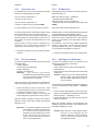
DICHIARAZIONE CE
EC DECLARACIÓN CE
DECLARAÇÃO CE
Schema Elettrico
WD Esquema Eléctrico
Esquema Eléctrico
Contenuto in SP
Integradas en SP
Conteúdos em SP
Contained in SP
Teil der SP
Contenu dans SP
Содержится в каталоге запчастей
EC DECLARATION
EC CE KONFORMITÄTSERKLÄRUNG
DECLARATION CE
ДЕКЛАРАЦИЯ ЕС
Wiring Diagram
WD Schaltplan
Schéma électrique
Схема электрических соединений
NOTE SULLA DOCUMENTAZIONE - ITA
NOTAS SOBRE LA DOCUMENTACIÓN - SPA
NOTAS SOBRE A DOCUMENTAÇÃO - POR
ENG - NOTES REGARDING DOCUMENTATION
DEU -
ANMERKUNGEN ZUR DOKUMENTATION
FRA - NOTES SUR LA DOCUMENTATION
RU - ПРИМЕЧАНИЯ ПО ДОКУМЕНТАЦИИ
DOCUMENTAZIONE DISPONIBILE
DOCUMENTAÇÃO DISPONÍVEL
DOCUMENTACIÓN DISPONIBLE
DOCUMENTATION AVAILABLE
DOCUMENTATION DISPONIBLE
VERFÜGBARE DOKUMENTATION
ДОСТУПНАЯ ДОКУМЕНТАЦИЯ
Pubblicazione di supporto al prodotto:
EQUILIBRATRICE
Publicación de soporte al producto:
EQUILIBRADORA
Documentação de apoio ao produto:
MÁQUINA DE EQUILIBRAR RODAS
edizione di lingua originale in: ITALIANO
edición original en idioma: ITALIANO
edição original em: ITALIANO
Data di prima pubblicazione:
Fecha de la primera publicación:
Data da primeira publicação:
Product aid publication:
WHEEL BALANCER
Zum Produkt gehörendes Dokument:
AUSWUCHTMASCHINEN
Publication de support au produit:
EQUILIBREUSE
Публикация для поддержки изделия:
БАЛАНСИРОВОЧНЫЙ СТАНОК
original language edition in: ITALIAN
Originalausgabe in: ITALIENISCH
langue d’origine de la publication: ITALIEN
оригинального издания: итальянский
Date of fi rst publication:
Datum der Erstveröffentlichung:
Date de la première édition:
дата первого издания:
06 / 2016
06 / 2016
SWB 100
ABB. DESCRIPTION CODE LANGUAGE
SIGLE DESCRIPTION CODE LANGUE
KENN. BESCHREIBUNG CODE SPRACHE
Operator’
s Manual
Manuel de l’Opérateur ZEEWB117A03
ENG-FRA-DEU
OM Betriebsanleitung
Руководство по эксплуатации
ZEEWB117A08 RU
Spare Parts Booklet ENG-FRA-DEU
SP Liste des pièces détachées TEEWB117A3 ITA-SPA-POR
Ersatzteilliste RU
Safety Booklet (Quick Start) EAZ0103G25A
ENG-FRA-DEU
QS Manuel de Securité EAZ0103G26A ITA-POR-SPA
Sicherheitsvorkehrungen
EAZ0103G27A RU
SIGLA DESCRIZIONE CODICE LINGUA
SIGLA DESCRIPCIÓN CÓDIGO IDIOMA
SIGLA DESCRIÇÃO CÓDIGO IDIOMA
Manuale Operatore
OM Manual de Operador ZEEWB117A05 ITA-SPA-POR
Manual do Operador
Libretto Ricambi ENG-FRA-DEU
SP tabla de repuestos TEEWB117A3 ITA-SPA-POR
Lista de peças RU
Libretto di Sicurezza EAZ0103G25A
ENG-FRA-DEU
SB Manual de Seguridad EAZ0103G26A ITA-POR-SPA
Manual de Segurança
EAZ0103G27A RU

iv
UPDATING REPORTS
DISCLAIMER OF WARRANTIES
AND LIMITATIONS OF LIABILITIES
While the authors have taken care in the preparation
of this manual, nothing contained herein:
- modifi es or alters in any way the standard
terms and conditions of the purchase, lease or
rental agreement under the terms of which the
equipment to which this manual relates was
acquired,
- increases in any way the liability to the customer
or to third parties.
TO THE READER
While every effort has been made to ensure that
the information contained in this manual is correct,
complete and up-to date, the right to change any part
of this document at any time without prior notice is
reserved.
Before installing, maintaining or
operating this unit, please read
this manual carefully, paying extra
attention to the safety warnings
and precautions.
Table of Contents
Table of contents iv
1.0 Safety 6
2.0 Speci! cations 8
3.0 Introduction 10
4.0
Layout 14
5.0 Operation 22
6.0 Maintenance 74
7.0
Trouble shotting 76
8.0 Disposing of the unit 88
9.0 Appendix 88
Appendix: Installation Instructions 91
Revision A
of June 2016
First document issue PCN: 16G0160

v
Inhaltsverzeichnis
Inhaltsverzeichnis v
1.0 Sicherheit 7
2.0 Spezi! kationen 9
3.0
Einfürung 11
4.0 Layout 15
5.0 Betrieb 23
6.0 Wartung 75
7.0 Fehlerbeseitigung 77
8.0 Entsorgung 89
9.0 Anhang 89
Anhang: Installationsanweisugen 91
GEWÄHRLEISTUNGS- UND
HAFTUNGSAUSSCHLUSS
Die Informationen in dieser Bedienungsanleitung wurden
gewissenhaft und sorgfältig zusammengestellt. Der Inhalt
oder Teile des Inhalts dieser Bedienungsanleitung:
- haben keinen Einfluß auf die Allgemeinen
Geschäftsbedingungen des Kaufvertrages,
Leasingvertrages oder Mietvertrages auf dessen
Grundlage das in dieser Bedienungsanleitung
beschriebene Maschine bezogen wurde,
- erweitern in keiner Weise den Haftungsanspruch
des Kunden oder Dritter.
AN DEN LESER
Bei der Zusam m enst ellu ng der in dieser
Bedienungsanleitung enthaltenen Informationen wurde
größten Wert auf deren Richtigkeit, Vollständigkeit und
Aktualität gelegt. Wir behalten uns jedoch ausdrücklich
das Recht vor, diese Informationen jederzeit und ohne
vorherige Ankündigung zu ändern.
Lesen Sie diese
Bedienungsanleitung sorgfältig
durch, bevor Sie die Maschine
installieren, warten oder betreiben.
Beachten Sie insbesondere die
Sicherheitsvorschriften und
Warnungen.
LIMITES D’APPLICATION DE LA GARANTIE ET
LIMITATIONS DE LA GARANTIE
Bien que les auteurs aient accordé la plus grande
attention à la rédaction du présent manuel, aucun
élément fi gurant dans ce dernier:
- ne modifi e les conditions et les termes standards
d’un accord d’achat en crédit-bail ou de location,
aux termes desquels les appareils traités dans
le présent manuel sont achetés,
- ou n’augmente la responsabilité de la société
envers le client ou les tiers.
POUR LE LECTEUR
Bien que tout effort ait été fait pour assurer l’exactitude
des informations fi gurant dans le présent manuel,
comme complément ou mise à jour de ce dernier, le
droit d’y apporter des modifi cations à tout moment sans
préavis est réservé.
Avant d’installer, d’entretenir ou d’uti-
liser la machine, lire attentivement le
présent manuel, en faisant particuliè-
rement attention aux avertissements
et précautions de sécurité.
Table des matieres
Table des matieres v
1.0 Sécurité 7
2.0 Speci!
cations 9
3.0 Introduction 11
4.0 Disposition 15
5.0
Utilisation 23
6.0
Entretien 75
7.0 Dépannage 77
8.0 Vente 89
9.0 Annexes 89
Annexe: Instructions d’Installation 91

6
1-1
WICHTIG!! DIESE ANLEITUNG IST
AUFZUBEWAHREN
IMPORTANT!! CONSERVER LES
PRÉSENTES INSTRUCTIONS
Safety
IMPORTANT!! SAVE THESE
INSTRUCTIONS
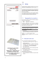
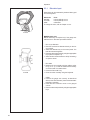
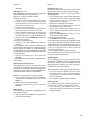
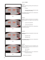
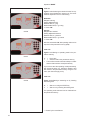
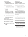
1.0 Safety
Important safety precautions relevant to the unit are
described in the Safety Booklet, refer to Figure 1 – 1.
The Safety Precautions should be fully understood and
observed by every operator. We suggest you store (a
copy) of the Safety Booklet near the unit, within easy
reach of the operator.
The Operator’s Manual will contain specifi c warnings
and cautions when dangerous situations may be
encountered during the procedures described.
1.1 Typographical conventions
This manual contains text styles intended to make the
reader pay extra attention:
Note: Suggestion or explanation.
CAU
TION: INDICATES THAT THE FOLLOWING
ACTION MAY RESULT IN DAMAGE TO THE UNIT
OR OBJECTS ATTACHED TO IT.
WARNING: INDICATES THAT THE FOLLOWING
ACTION MAY RESULT IN (SERIOUS) INJURY TO
THE OPERATOR OR OTHERS.
• Bulleted list:
• Indicates that action must be taken by the operator
before proceeding to the next step in the sequence.
TOPIC (F n°) = see the Chapter number.
The topic indicated is explained in full in the charter
specifi er.
1.2 Manuals for the unit
The unit includes the following documentation:
- Safety Booklet (standard supplement , Fig. 1-1)
- Operator’
s Manual
The operator must learn in detail the instructions
contained in them and meticulously observe the
notes HAZARD and CAUTION WARNINGs.
- Spare Parts Booklet
Document used only by the Technical Support staff.
Installation instructions
The installation instructions are in the Appendix of
the Operator Manual.
EC Declaration of Conformity
The EC Declaration is included in the Spare Parts
Booklet.
P/N: EAZ0103G25A

7
Sicherheit
1.0 Sicherheit
Wichtige Sicherheitsmaßnahmen für dieses Gerät
sind im Sicherheitshandbuch beschrieben; siehe
Abbildung 1-1.
Die Sicherheitsmaßnahmen müssen von allen
Bedienern verstanden und eingehalten werden.
Wir empfehlen, eine Kopie des Sicherheitshefts in
der Nähe des Geräts gut sichtbar für den Bediener
aufzubewahren.
Das Bedienungshandbuch enthält spezifische
Warnungen und Hinweise, wenn bei den beschriebenen
Maßnahmen gefährliche Situationen auftreten können.
1.1 Typographie
Dieses Handbuch enthält Schriftweisen, die zu
besonderer V
orsicht auffordern:
Anmerkung:
Vorschlag oder Erklärung
VORSICHT: WEIST DARAUF HIN, DASS DIE
FOLGENDE MASSNAHME ZU SCHÄDEN AM
GERÄT ODER DARAN BEFESTIGTEN TEILEN
FÜHREN KANN.
WARNUNG: WEIST DARAUF HIN, DASS DIE
FOLGENDE MASSNAHME ZU (SCHWEREN)
VERLETZUNGEN DES BEDIENERS ODER
ANDERER PERSONEN FÜHREN KANN.
• Aufzählungspunkte:
• Zeigen an, dass der Bediener Maßnahmen
durchführen muss, bevor er zum nächsten Schritt
des Vorgangs übergehen kann.
THEMA F Nr. (= siehe Kapitel Nummer).
Das angegebene Thema wird in dem bezeichneten
Kapitel ausführlich behandelt.
1.2 Handbücher des Geräts
Das Gerät ist mit folgender Dokumentation ausgestatt
et:
-
Sicherheitsheft (Standardbeilage, Abb. 1-1).
- Betriebsanleitung
Der Benutzer muss die darin enthaltenen
Anweisungen im Detail erfassen und die Hinweise,
die WARNUNGEN vor Gefahren und die Angaben
mit der Bezeichnung ACHTUNG genauestens
befolgen.
- Ersatzteilhandbuch
Dieses Dokument ist dem Wartungspersonal
vorbehalten.
Installationsanweisungen
Die Installationsanweisungen fi nden Sie in der
Anlage der Betriebsanleitung.
CE-Konformitätserklärung
Die CE-Konformitätserklärung befi ndet sich im
Ersatzteilhandbuch.
Sécurité
1.0 Sécurité
Les mesures de sécurité importantes relatives à l’unité
sont décrites dans le Livret de Sécurité et résumées
Figure 1-1.
Chaque opérateur doit totalement comprendre les
mesures de sécurité. Nous suggérons de conserver
une copie du Livret de Sécurité près de la machine à
la portée de l’opérateur.
Le Manuel de l’Opérateur contient des avertissements
et des mesures de prudence spécifiques à des
situations potentiellement dangereuses qui peuvent
se produire durant les procédures décrites.
1.1 Typographie
Ce manuel contient des styles de texte qui vous
demande de prêter une attention particulière :
Remarque : Suggestion ou explication.
ME
SURE DE PRUDENCE : INDIQUE QUE L’ACTION
SUIVANTE RISQUE D’ENDOMMAGER LA MACHINE
ET DES OBJETS ATTACHES A LA MACHINE.
AVERTISSEMENT : INDIQUE QUE L’ACTION
SUIVANTE RISQUE DE CAUSER DES BLESSURES
(SERIEUSES) A L’OPERATEUR OU AUTRES.
• Liste à puces :
• Indique que l’opérateur doit effectuer une action
avant de pouvoir passer à l’étape suivante de la
séquence.
ARGUMENTO (F n°) = ir para o número do capítulo.
A actualização indicada è tratada dentro do capítulo
especifi cado.
1.2 Manuels de la machine
La machine est accompagnée des manuels suivants:
-
Livret de Sécurité
(supplément de norme, Fig. 1-1)
- Manuel d’utilisation (Chapitre 1 – 9) L’utilisateur
doit apprendre dans le détail les instructions que
ce manuel contient et observer scrupuleusement
les remarques, les MISES EN GARDE de danger
et d’ATTENTION
-
Tables et Listes des Pièces de Rechange Document
à usage exclusif du personnel d’assistance.
Instructions pour l’installation
Les instructions pour l’Installation se trouvent dans
l’Appendice du Manuel d’utilisation.
Déclaration de Conformité CE
La Déclaration CE fi gure dans la Notice des Pièces
détachées.

8
230V~, 50/60 Hz, 1 ph
1,1 A
0,12 KW
(2x)IEC 127 T 6,3A
>6 sec.
<100 rpm
0–250 mm
1/5 g o 0,05/0,25 oz
20” (508 mm)
35” (900 mm)
70 Kg (154 lbs)
1-20” (25-508mm)
8-25”
8-32”
40 mm
70 Kg
90 Kg
1711x1005x1100 mm
1180x940x760 mm
<70 db(A)
0-50 °C
10-90%
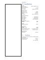
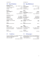
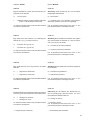
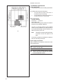
Specifi cations
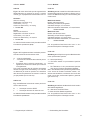
2.0 Speci! cations
Power:
Power Supply
Power consumption
Motor rating
Mains fuses
Measurements:
Measuring time
Measuring speed
O
ffset
Resolution
Wheel dimensions:
Max. width
Max. diameter
Max. weight
Rim width
Rim diameter:
NORMAL, ALU, ST
ATIC
Manual
Shaft:
Stub shaft diameter
Dimensions:
Weight
Shipping weight
Max. Dimensions (hxdxw)
Shipping dimensions
Miscellaneous:
Noise level
2.1 Conditions
During use or long term storage, the conditions shou
ld
never exeed:
Temperature range
Humidity range
non condensing

9
230V~, 50/60 Hz, 1 ph
1,1 A
0,12 KW
(2x)IEC 127 T 6,3A
>6 sec.
<100 rpm
0–250 mm
1/5 g o 0,05/0,25 oz
20” (508 mm)
35” (900 mm)
70 Kg (154 lbs)
1-20” (25-508mm)
8-25”
8-32”
40 mm
70 Kg
90 Kg
1711x1005x1100 mm
1180x940x760 mm
<70 db(A)
0-50 °C
10-90%
230V~, 50/60 Hz, 1 ph
1,1 A
0,12 KW
(2x)IEC 127 T 6,3A
>6 sec.
<100 rpm
0–250 mm
1/5 g o 0,05/0,25 oz
20” (508 mm)
35” (900 mm)
70 Kg (154 lbs)
1-20” (25-508mm)
8-25”
8-32”
40 mm
70 Kg
90 Kg
1711x1005x1100 mm
1180x940x760 mm
<70 db(A)
0-50 °C
10-90%
Spezifi kationen
2.0 Spezi• kationen
Strom:
Stromversorgung
Stromverbrauch
Motorwerte
Netzsicherungen
Daten:
Messzeit
Messdrehzahl
Abstand Maschine/Felgenhorn
Aufl
ösung
Radmaße:
Max. Breite
Max. Durchmesser
Max. Gewicht
Felgenbreite
Felgendurchmesser:
NORMAL,
ALU, STATISCH
Manuell
Welle:
Hauptwellendurchmesser
Maße:
Gewicht
Versandgewicht
Max. Maße (HxTxB)
Versandmaße
Anderes:
Geräuschpegel
2.1 Bedingungen
Während der Benutzung bzw. einer Langzeitlagerung
d
ür
fen die folgenden Werte nicht überschritten werden.
Temperaturbereich
Luftfeuchtigkeitsbereich
nicht kondensierend
Specifi cations
2.0 Speci• cations
Données électrices :
Alimentation
Consommation électrique
Puissance moteur
Fusibles
Mesures :
Durée des mesures
V
itesse rotation
Ecart
Résolution
Dimensions de roue :
Largeur max.
Diamètre max.
Poids max.
Largeur de la jante
Diamètre de la jante:
NORMAL, ALU, ST
ATIQUE
Manuel
Arbre :
Diamètre de bout d’arbre
Misure:
Poids
Poids d’expédition
Dimensions max. (hxdxl)
Dimensions d’expédition
Divers :
Niveau sonore
2.1 Conditions
Lors d’une utilisation ou un stockage prolongé les
conditions ne doivent jamais dépasser :
Gamme de températures
Gamme d’humidité
sans formation de buée

10
Introduction
3.0 Introduction
This wheel balancer combines advanced, high-
per
formance technology, robustness and reliability with
very simple, user-friendly operation.
The low rotation speed of the wheel ensures that this
balancer is very safe.
It is characterised by a display and input panel which
are easy to use and guarantee rapid, intuitive operation.
Operator time and effort are reduced to a minimum,
while maintaining accuracy and reliability.
Always work in a clean area and with clean wheels,
no dirt stuck in the tyre or on the rim. That way proper
mounting of the wheel and an optimal balancing result
can be achieved.
Application
The off-the-vehicle wheel balancer is designed for
dynamic and static balancing of passenger car and
light-truck wheels, that fall within the limits stated in
the technical specifi cations.
This is a high accuracy measuring device. Handle
with care.

11
Einführung
3.0 Einführung
Dieses Auswuchtgerät verbindet hochmoderne
Hoc
hleistungstechnik, Robustheit und Zuverlässigkeit
mit einfachem, benutzerfreundlichem Betrieb.
Durch die niedrige Rotationsgeschwindigkeit des
Rades ist das Auswuchtgerät extrem sicher in der
Benutzung.
Es ist mit einem einfach zu benutzenden Display-
und Eingabefeld ausgestattet, was eine schnelle und
intuitive Benutzung gewährleistet.
Die Bedienungszeit und der Bedienungsaufwand
sind auf ein Minimum reduziert, ohne jedoch die
Genauigkeit und die Beständigkeit zu beeinträchtigen.
Arbeiten Sie immer in einer sauberen Umgebung
und mit sauberen Rädern, an denen weder an Reifen
noch an der Felge Schmutz klebt. Auf diese Weise ist
sichergestellt, dass das Rad richtig aufgespannt wird
und eine optimale Auswuchtung erzielt wird.
Einsatzbereich
Das Auswuchtgerät für demontierte Räder wurde zur
statischen und dynamischen Auswuchtung von Rädern
von Personenkraftwagen und leichten Lkws entwickelt,
die in den Bereich der angegebenen technischen
Spezifikationen fallen. Dies ist ein hochgenaues
Messgerät. Behandeln Sie es pfl eglich.
Introduction
3.0 Introduction
Cette équilibreuse vous offre une technologie avancé
e
de haute performance, solidité et fiabilité et son
opération est très simple et conviviale.
La faible vitesse de rotation de la roue assure que
cette équilibreuse peut être utilisée en toute sécurité.
Son Clavier affi cheur, simple à utiliser vous assure une
opération rapide et intuitive.
Le temps et l’effort d’utilisation sont réduits au minimum
mais la précision reste constante.
Travaillez toujours dans un endroit propre avec des
roues propres, pas de pneus ou jantes sales. Ainsi
vous obtiendrez une installation correcte de la roue
et des résultats d’équilibrage parfaits.
Application
Cette équilibreuse roues démontéespermet de mesurer
ledéséquilibre dynamique et statique des roues de
voitures et de camionnettes, qui se trouvent dans les
limites mentionnées des spécifi cations techniques.
Ceci est un appareil de mesure de haute précision.
Manipuler avec soin.

12
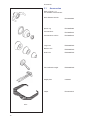
3.1-1
EAA0263G66A
EAA0277G61A
EAC0058D08A
EAC0058D07A
EAC0058D15A
EAM0005D25A
EAM0005D24A
EAM0005D23A
EAM0005D40A
8-04250A
EAA0247G21A
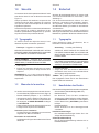
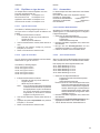
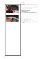
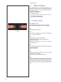
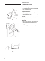
Accessories
3.1 Accessories
Refer to Figure 3.1-1.
The standard accessories are:
Quick-Release Hub Nut
Quick-clamping MZV (Ring-Nut)
Spacer ring
Universal drum
Universal drum cushion
Large cone
Medium cone
Small cone
User Calibration weight
W
eight pliers
Caliper

13
EAA0263G66A
EAA0277G61A
EAC0058D08A
EAC0058D07A
EAC0058D15A
EAM0005D25A
EAM0005D24A
EAM0005D23A
EAM0005D40A
8-04250A
EAA0247G21A
EAA0263G66A
EAA0277G61A
EAC0058D08A
EAC0058D07A
EAC0058D15A
EAM0005D25A
EAM0005D24A
EAM0005D23A
EAM0005D40A
8-04250A
EAA0247G21A
Zubehör
3.1 Zubehör
Siehe Abbildung 3.1-1.
Das folgende Standardzubehör steht zur V
erfügung:
Schnellspannmutter
Quickmutter MZV
Distanzring
Drucktopf
Schützring für Drucktopf
Großer Konus
Mittlerer Konus
Kleiner Konus
Benutzerkalibriergewicht
Gewichtzange
Meßlehre
Accessoires
3.1 Accessoires
Se reporter à la Figure 3.1-1.
Les accessoires standard sont:
Manivelle de serrage rapide
Ecrou à serrage rapide MZV
Disque de distance
Coupelle plastique
Joint protection de la coupelle
Grand cône
Cône moyen
Petit cône
Masse de calibrage utilisateur
Pince à masses
Calibre largeur jantes

14
1
2
3
4
6
7
8
1
2
9
5
4-1
4-2
OFF
ON
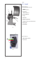
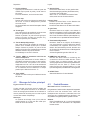
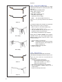
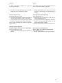
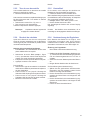
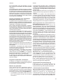
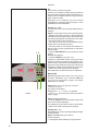
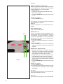
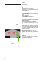
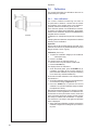
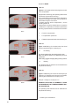
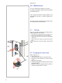
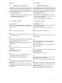
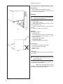
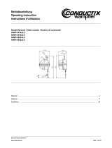
Layout
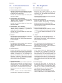
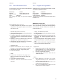
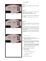
4.0 Layout
Refer to Figure 4-1.
Functional description of the unit:
1. Display
Refer to Chapter 4.1.
2. Input panel
Refer to Chapter 4.2.
3. Internal gauge arm
4. Flange
5. Stub shaft
6. Weight compartments
7. Storage areas for cones and hub nuts
8. Wheel guard
9. Brake Wheel
Refer to Figure 4-2.
1.
Mains switch (ON/OFF)
2. Power inlet

15
Layout
4.0 Layout
Siehe Abbildung 4-1.
Funktionsbeschreibung des Geräts:
1. Display
Siehe Kapitel 4.1.
2. Eingabefeld
Siehe Kapitel 4.2.
3. Innerer Messarm
4.
Flansch
5. Flanschwelle
6. Gewichtefächer
7. Aufbewahrungsbereiche für Konen oder
Spannteile
8. Radschutz
9. Bremsrad
Siehe Abbildung 4-2.
1.
Netzschalter (AN/AUS)
2. Netzanschluss
Disposition
4.0 Disposition
Se reporter à la Figure 4-1.
Description fonctionnelle de la machine :
1. Af! chage
Se reporter au Chapitre 4.1
2. Clavier
Se reporter au Chapitre 4.2
3. Jauge de déport interne
4. Montage
5. Embout d’arbre
6. Bac porte-plombs
7. Zones de stockage pour cônes et outils de
blocage
8. Carter de roue
9. Frein de roue
Se reporter à la Figure 4-2.
1.
Interrupteur secteur (ALLUMÉ / ÉTEINT)
2.
Branchement electrique

16
4.1-1
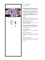
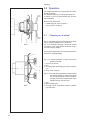
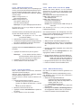
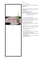
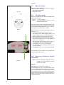
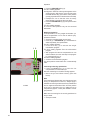
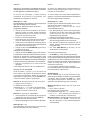
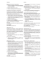
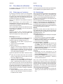
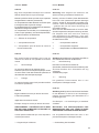
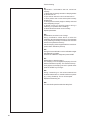
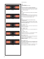
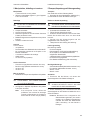
Layout
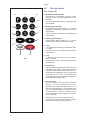
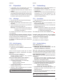
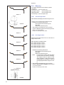
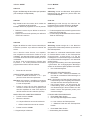
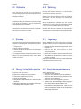
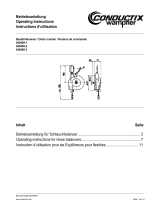
4.1 The display
Refer to Figures 4.1-1.
1. Rotation indicators of the correction plane.
The indicators show the direction the operator has
to rotate the wheel (by hand) after a balancing run.
2. Weight Application Position (WAP) indicator.
The indicator will light up when the wheel is in the
correct position for weight application. This indicator
will be referred to as the WAP indicator.
Refer to the weight mode selected before applying
a weight!
3. Display.
Depending on the stage of the program the display
gives the operator information about rim sizes,
balancing weights, error codes, etc.
4. Weight units indicator, “Oz”.
The
indicator will
light if the weight is displayed in
ounces instead of grams.
5. Motorcycle Dynamic and Static Indicator.
The indicator lights up when you activate the
motorcycle wheel balancing program or the single
weight (static mode).
6. Flange compensation.
This indicator lights up when fl ange compensation
is activated
7. Weight Position Indicator.
Apply a clip-on weight to the rim at the position
indicated when the WAP indicator for this plane
lights up.
8.
Weight Position Indicator.
Apply a stick-on weight to the rim at the position
indicated when the WAP indicator for this plane
lights up.
64 51
27 8 7
33
8
4

17
Layout
4.1 Das Display
Siehe Abbildungen 4.1-1.
1. Rotationsanzeige der Korrekturebene.
Die
Anzeigen geben die Richtung an, in der
der Bediener das Rad (per Hand) nach einer
Auswuchtrotation drehen muss.
2. Gewichtanbringungspositionsanzeige (WAP).
Die Anzeige leuchtet ganz auf, wenn sich das
Rad in der richtigen Stellung zur Anbringung des
Gewichts befi ndet.
Diese Anzeige wird als WAP-Anzeige bezeichnet.
Achten Sie auf den gewählten Gewichtsmodus,
bevor Sie ein Gewicht anbringen!
3. Display.
Je nach Stand des jeweiligen Programms gibt
das Display dem Bediener Informationen über
Felgengröße, Auswuchtgewichte, Fehlercodes,
usw..
4. Gewichtseinheitsanzeige, “Oz”.
Diese Anzeige leuchtet auf, wenn das Gewicht in
Unzen anstatt in Gramm angegeben wird.
5. Anzeige Motorrad Dynamisch und Statisch
Die Anzeige leuchtet bei Aktivierung des Programms
zur Auswuchtung von Motorradrädern auf.
6. Kompensation des Flansches.
Diese A n zeige leu c htet auf, wenn die
Kompensations des Flansches aktiviert wird.
7. Gewichtanbringungspositionsanzeige.
Befestigen Sie ein Klemm- oder ein Klebegewicht
an der angegebenen Felgenposition, wenn die
WAP-Anzeige dieser Ebene aufl euchtet.
8.
Gewichtanbringungspositionsanzeige.
Befestigen Sie ein Klebegewicht an der
angegebenen Felgenposition, wenn die WAP-
Anzeige dieser Ebene aufl euchtet.
Disposition
4.1 L’af! chage
Se reporter à la Figure 4.1-1.
1.
Indicateurs de position de masses correctives
Les indicateurs indiquent la direction vers laquelle
l’opérateur doit tourner la roue (manuellement)
après un équilibrage.
2. Indicateur (WAP) Position de la Pose des
Masses
L’indicateur s’allume quand la roue est dans la
position correcte pour la pose des masses. Cet
indicateur est appelé indicateur WAP.
Se reporter au type de roue sélectionné avant de
poser la masse !
3. Af! chage
Lors des différentes étapes du programme
l’affi chage donne à l’opérateur des renseignements
sur la taille des jantes, les masses d’équilibrage,
les codes erreur, etc.
4. Indicateur “Oz” d’unités de poids
Cet indicateur s’allume si le poids est affi ché en
onces au lieu de grammes.
5. Indicateur Equilibrage roue mode dynamique
et statique moto.
L’indicateur s’allume à l’activation du programme
d’équilibrage des roues moto.
6. Compensation de la bride
Cet indicateur s’allume lors de la sélection du
compensation de la bride.
7. Indicateur de position des masses.
Poser une masse agrafée ou adhésive à la position
de jante indiquée quand l’indicateur Position masse
de ce plan s’allume.
8.
Indicateur de position des masses.
Poser une masse adhésive à la position de jante
indiquée quand l’indicateur “WAP” de ce plan
s’allume.

18
13 9
5
1
3
2
11
6
10
12
8
4
7
4.2-1
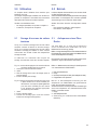
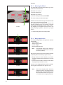
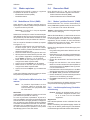
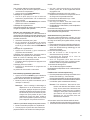
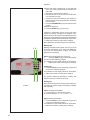
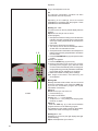
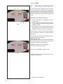
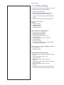
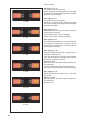
Layout
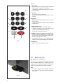
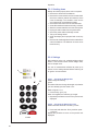
4.2 The input panel
Refer to Figure 4.2-1.
1. Diameter key with indicator.
Press to select “rim diameter” mode, the current
diameter or “dia” value will appear and the unit
will beep.
The current value will be shown on the display and
can be edited.
2. Width key with indicator.
Press to select “rim width” mode, the [¦- - -¦] symbol
will appear, representing the width value and the
unit will beep.
The current value will be shown on the display and
can be edited.
3. Offset key with indicator.
Press to select “Offset” mode, the ---I or current
offset value will appear and the unit will beep.
4. + key.
To increase an input value (e.g. rim diameter, offset,
rim width).
Hold the key down to increase the values shown
automatically.
5. - key.
To decrease an input value (e.g. rim diameter,
offset, rim width).
Hold down the key to reduce the values shown
automatically.
6. Function key.
Activates the second function of multi-function keys
(indicated by the graphics on the lower section of
the keys). Press this key and F appears on the
left display then disappears when you press one
of the function keys. The F on the display also
disappears when you press the function key again
(it is sometimes used like enter).
7. Fine key (Lens)
Press to toggle the read-out accuracy between
Normal, i.e. 25, 50 or 100 grams (0,5,1 or 2 oz)
depending on the registered value and Fine i.e. 10
grams (0.5oz) regardless of the registered value.
The unit will beep. Release the key to return to
normal accuracy. F+Fine key activates the car
wheel optimisation and minimisation operation.
The unit will beep.
Release the key to return to normal accuracy.
F+Fine key; activates the PRO MATCH function,
optimisation and minimisation procedure.

19
Layout
4.2 Das Eingabefeld
Siehe Abbildung 4.2-1.
1. Durchmesser-Taste mit
Anzeige.
D r ü c k e n S i e d i e s e Ta s t e , u m d e n
„Felgendurchmesser”-Modus zu wählen. Es
erscheinen „dia”, der aktuelle Durchmesserwert,
und das Gerät piept.
Der aktuelle Werte wird auf dem Display dargestellt
und kann geändert werden.
2. Breiten-Taste mit Anzeige.
Drücken Sie diese Taste, um den „Felgenbreiten”-
Modus zu wählen. Das Symbol [¦- - -¦] und der
Breitenwert erscheinen und das Gerät piept.
Der aktuelle Werte wird auf dem Display dargestellt
und kann geändert werden.
3. Abstand-Taste mit Anzeige.
Drücken Sie diese Taste, um den Modus “Abstand”
(“Offset”) zu wählen. Es erscheinen die Anzeige
“- - -¦” und der aktuelle Abstandswert und das
Gerät piept.
4. + Taste
Zur Erhöhung des Eingabewertes (z. B.
Felgendurchmesser, Abstand, Felgenbreite).
Halten Sie die Taste gedrückt, um den angezeigten
Wert automatisch zu erhöhen.
5. - Taste
Zur Verringerung des Eingabewertes (z. B.
Felgendurchmesser, Abstand, Felgenbreite).
Halten Sie die Taste gedrückt, um den angezeigten
Wert automatisch zu verringern.
6. Funktionstaste
Um die zweite Funktion der Multifunktionstasten
zu aktivieren (sie ist graphisch im unteren Teil
der Tasten dargestellt). Bei Drücken dieser
Taste erscheint “F” auf dem linken Display und
verschwindet wieder, wenn man danach eine der
Funktionstasten drückt. Das “F” verschwindet auch
vom Display, wenn man die Taste noch einmal
drückt (manchmal wird sie auch als “Enter”-Taste
verwendet).
7. Fein-Taste (Lupe)
Drücken Sie diese Taste, um zwischen der
Anzeigegenauigkeit Normal, d.h. 25, 50 oder 100
(0,5, 1 oder 2 Unzen) je nach gemessenem Wert,
und Fein, d.h. 10 Gramm (0,5 Unzen) unabhängig
vom erfassten Wert, hin und her zu schalten.
Wenn man „F” und danach die Feinan-
zeige-Taste drückt, wird die Funktion zum Opti-
mieren und Minimieren von Pkw-Rädern aktiviert.
Disposition
4.2 Le Panneau de Données
Se reporter à la Figure 4.2-1.
1.
Touche diamètre avec indicateur
Appuyer sur cette touche pour sélectionner le mode
“diamètre de jante”. L’indicateur diamètre s’allume,
la machine émet un bip sonore.
La valeur en cours est indiquée sur l’écran, elle
peut être modifi ée.
2. Touche largeur avec indicateur
Appuyer sur cette touche pour sélectionner le mode
“largeur de jante”. L’indicateur
[¦- - -¦] s’allume, la
machine émet un bip sonore.
La
valeur en
cours est indiquée sur l’écran, elle
peut être modifi ée.
3. Touche déport avec indicateur.
Appuyer sur cette touche pour sélectionner le mode
“déport” (“Offset”). L’indicateur [- - -¦] s’allume, la
machine émet un bip sonore.
La valeur en cours est indiquée sur l’écran, elle
peut être modifi ée.
4. Touche +
Pour augmenter la valeur d’entrée (par ex. diamètre
de jante, déport, largeur de jante).
Maintenir appuyé pour changer automatiquement
la valeur indiquée.
5. Touche -
Pour diminuer la valeur d’entrée (par ex. diamètre
de jante, déport, largeur de jante).
Maintenir pour changer automatiquement la valeur
indiquée.
6. Touche Fonction
Presser cette touche pour activer la seconde
fonction
de touches
multi-fonction (graphiquement
visualisé dans la partie inférieure des touches
mêmes). L’’indication “F” sur l’affichage à la
gauche Il sera affi ché lorsque la touche “F” sera
sélectionné. L’indication “F” disparaîtra en pressant
de nouveau la touche, (parfois la touche est utilisée
aussi comme fonction de “ENTER”).
7. Touche ! ne (Loupe)
Appuyer sur cette touche pour basculer la précision
de lecture entre le Normal, c’est-à-dire 25, 50 ou
100 grammes (0,5, 1 o 2 oz), selon le valeur relevée
et 10 grammes (0,5 oz), indépendamment de la
valeur relevée. . La machine émet un bip sonore.
Relâcher la touche pour revenir à la précision
normale.
F+Fine ; active la fonction
“PRO MATCH”,
procédure de la optimisation et minimisation.

20
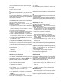
4.2-1
4.2-2
13 9
5
1
3
2
11
6
10
12
8
4
7
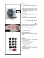
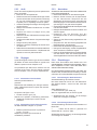
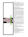
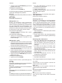
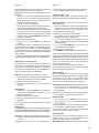
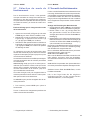
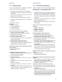
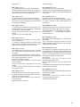
Layout
8. Weight key
Press to select the required weight application
mode (weight mode), the unit will beep.
F
+Weight key; activates the Motorcycles wheel
balancing Mode.
9. Stop key.
Press to stop spinning the wheel.
The STOP key also has an emergency stop
function.
10. g/oz key.
Toggles between reading in grams and in ounces,
and vice versa.
F+g/oz; activates the C-Code functions, special
user functions.
11. Static/Dynamic key.
Toggles between dynamic and static modes.
F+Stat/Dyn; activates the function for balancing with
a stick-on counterweight inside the tyre.
The INT LED on the panel lights up.
12.
SWM key, hidden weight split and mm/inch Key
Press to select the SWM function, hidden weight
split.
This can
only be activated after selecting the
ALU2P/ALU3P application mode.
In combination with the “F” key, toggles between
readings in inches (default setting) and millimeters.
13. START key.
Starts the machine spinning the wheel.
4.3 Main shaft lock
Fig. 4.2-2 Pedal of main shaft lock
T
he
main shaft is locked when the pedal is depressed.
This facilitates tightening or untightening of the
clamping nut and retains the wheel in the correction
position for correct fi tting of the balance weights.
Note:
This lock is designed only to facilitate orientation
of the wheel and must not be used for braking the
main shaft.
La page est en cours de chargement...
La page est en cours de chargement...
La page est en cours de chargement...
La page est en cours de chargement...
La page est en cours de chargement...
La page est en cours de chargement...
La page est en cours de chargement...
La page est en cours de chargement...
La page est en cours de chargement...
La page est en cours de chargement...
La page est en cours de chargement...
La page est en cours de chargement...
La page est en cours de chargement...
La page est en cours de chargement...
La page est en cours de chargement...
La page est en cours de chargement...
La page est en cours de chargement...
La page est en cours de chargement...
La page est en cours de chargement...
La page est en cours de chargement...
La page est en cours de chargement...
La page est en cours de chargement...
La page est en cours de chargement...
La page est en cours de chargement...
La page est en cours de chargement...
La page est en cours de chargement...
La page est en cours de chargement...
La page est en cours de chargement...
La page est en cours de chargement...
La page est en cours de chargement...
La page est en cours de chargement...
La page est en cours de chargement...
La page est en cours de chargement...
La page est en cours de chargement...
La page est en cours de chargement...
La page est en cours de chargement...
La page est en cours de chargement...
La page est en cours de chargement...
La page est en cours de chargement...
La page est en cours de chargement...
La page est en cours de chargement...
La page est en cours de chargement...
La page est en cours de chargement...
La page est en cours de chargement...
La page est en cours de chargement...
La page est en cours de chargement...
La page est en cours de chargement...
La page est en cours de chargement...
La page est en cours de chargement...
La page est en cours de chargement...
La page est en cours de chargement...
La page est en cours de chargement...
La page est en cours de chargement...
La page est en cours de chargement...
La page est en cours de chargement...
La page est en cours de chargement...
La page est en cours de chargement...
La page est en cours de chargement...
La page est en cours de chargement...
La page est en cours de chargement...
La page est en cours de chargement...
La page est en cours de chargement...
La page est en cours de chargement...
La page est en cours de chargement...
La page est en cours de chargement...
La page est en cours de chargement...
La page est en cours de chargement...
La page est en cours de chargement...
La page est en cours de chargement...
La page est en cours de chargement...
La page est en cours de chargement...
La page est en cours de chargement...
La page est en cours de chargement...
La page est en cours de chargement...
La page est en cours de chargement...
La page est en cours de chargement...
La page est en cours de chargement...
La page est en cours de chargement...
La page est en cours de chargement...
La page est en cours de chargement...
-
 1
1
-
 2
2
-
 3
3
-
 4
4
-
 5
5
-
 6
6
-
 7
7
-
 8
8
-
 9
9
-
 10
10
-
 11
11
-
 12
12
-
 13
13
-
 14
14
-
 15
15
-
 16
16
-
 17
17
-
 18
18
-
 19
19
-
 20
20
-
 21
21
-
 22
22
-
 23
23
-
 24
24
-
 25
25
-
 26
26
-
 27
27
-
 28
28
-
 29
29
-
 30
30
-
 31
31
-
 32
32
-
 33
33
-
 34
34
-
 35
35
-
 36
36
-
 37
37
-
 38
38
-
 39
39
-
 40
40
-
 41
41
-
 42
42
-
 43
43
-
 44
44
-
 45
45
-
 46
46
-
 47
47
-
 48
48
-
 49
49
-
 50
50
-
 51
51
-
 52
52
-
 53
53
-
 54
54
-
 55
55
-
 56
56
-
 57
57
-
 58
58
-
 59
59
-
 60
60
-
 61
61
-
 62
62
-
 63
63
-
 64
64
-
 65
65
-
 66
66
-
 67
67
-
 68
68
-
 69
69
-
 70
70
-
 71
71
-
 72
72
-
 73
73
-
 74
74
-
 75
75
-
 76
76
-
 77
77
-
 78
78
-
 79
79
-
 80
80
-
 81
81
-
 82
82
-
 83
83
-
 84
84
-
 85
85
-
 86
86
-
 87
87
-
 88
88
-
 89
89
-
 90
90
-
 91
91
-
 92
92
-
 93
93
-
 94
94
-
 95
95
-
 96
96
-
 97
97
-
 98
98
-
 99
99
-
 100
100


dans d''autres langues
- English: Snap-On Sun SWB 100 User manual
- Deutsch: Snap-On Sun SWB 100 Benutzerhandbuch
Documents connexes
Autres documents
-
Hofmann geodyna 7300 Mode d'emploi
-
 Snap-on Equipment JohnBean B2000P Series Manuel utilisateur
-
 M&B Engineering WB 277-N Original Instructions Manual
-
-
HWM PCorr Mode d'emploi
-
GYS METER 052093 Electronic Measurement Device Manuel utilisateur
-
-
 Conductix Wampfler Balancer Manuel utilisateur
-
 Conductix Wampfler Hose Balancers Manuel utilisateur
-
Redmond RMC-M4502E Le manuel du propriétaire


