Snap-On EEWB334A Operation Instructions Manual
- Taper
- Operation Instructions Manual

OPERATION INSTRUCTIONS MODE D’EMPLOI MANUAL DE OPERADOR
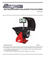
The off-the-vehicle wheel balancer is designed for dynamic and static balancing of
passenger car and light-truck wheels, that fall within the limits stated in the technical
speci• cations.
This is a high accuracy measuring device. Handle with care.
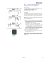
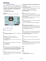
MOTORIZED WHEEL BALANCER TOUCHSCREEN
EEWB334A

2
EEWB334A

3
EEWB334A
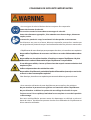
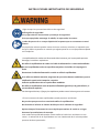
IMPORTANT SAFETY INSTRUCTIONS
• Basic safety precau• ons should always be followed.
Wear safety goggles.
Read and follow all Instruc! ons and safety messages.
Wear appropriate clothing; keep hair and loose fi # ng clothing, your hands
and all parts of your body away from moving parts.
Eye injury or other bodily injury can result from fl ying par• cles or entanglement with
moving parts.
• Electric powered wheel balancer can cause shocks, fi re or explosion.
Do not operate the wheel balancer with a damaged power cord or plug.
Do not use on wet surfaces, outdoors or expose the balancer to rain.
Unplug the power cord when the balancer is not in use.
If an extension cord is used, make sure that it is in good condi! on and that the cur-
rent ra! ng is 8 Amps or higher.
Use only in well ven! lated areas.
Do not operate the balancer in the vicinity of fl ammable liquids (gasoline) or below
grade or in an explosive atmosphere.
Electric shock, fi re or explosion can cause serious injury or death.
• Misuse of this wheel balancer can result in accidents.
Do not allow untrained or unauthorized personnel to operate the balancer.
Do not disable or bypass the hood safety interlock system.
Always securely ! ghten the quick nut that holds the wheel in place during the
moun! ng procedure.
Improperly balanced wheels can cause damage to the vehicle or automo• ve acci-
dents. Personal injury can result from altera• on to the balancer or improper use.
We
an
Ey
Ey
Ey
Ey
Ey
Ey
Ey
Ey
Ey
Ey
Ey
Ey
Ey
Ey
Ey
Ey
Ey
Ey
Ey
Ey
Ey
Ey
Ey
Ey
Ey
Ey
Ey
mo
gr
El
If
re
Us
Do
Do
Do
Do
Do
Do
Do
Do
Do
Do
Do
Do
Do
Do
Do
Do
Do
Do
Do
Do
Do
Do
Do
Do
Do
Do
Do
Do
Do
Do
Do
Do
Do
Do
Do
Do
Do
Do
Do
Do
Un
Un
Un
Un
Un
Un
Un
Un
Un
Un
Un
Un
Un
Un
Un
Un
Un
Un
Un
Un
Un
Un
Un
Un
Un
Un
Un
Un
Un
Un
Un
Un
Un
Un
Un
Un
Un
Un
Un
Un
Un
Un
Un
Un

4
EEWB334A
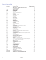
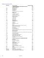
Table of Contents (EN)
Section Section T
itle Page Number
IMPORTANT SAFETY INSTRUCTIONS 3
Table of contents 4
1.0 Speci! cations 5
2.0 Conditions 5
3.0 Introduction 5
3.1 Accessories 6
3.2 Optional balancers Accessories 7
4.0 Layout 8
4.1 The screen 9
4.2 Pictographs – Symbols 16
4.3 Main shaft lock 18
4.4 SAPE Arm 18
4.5 Sonar sensor 18
4.6 Laser Pointer 18
4.7 Help information 19
4.8 Stop Button 19
5.0 Operation 20
5.1 Clamping a wheel 20
5.1.1 Unclamping the Wheel 20
5.2 Preparation 21
5.2.1 Power up 21
5.2.2 Status at Switching On 21
5.2.3 Settings 22
5.2.4 Shutting Down 22
5.3 Weight application and Measurement methods 23
5.4 Data detection mode 25
5.4.1 Selecting the Type of Vehicle 25
5.4.2 Manual Mode 26
5.4.3 Automatic Mode 27
5.5 Easy ALU Functions 28
5.6 Automatic Rim Dimension Reading, Setting and Alu Mode 29
5.7 Balancing 30
5.7.1 Measuring Imbalance 30
5.8 Weight application 31
5.8.1 Alu 2P and Alu 3P (HWM) Weight Modes: Using the SAPE Arm 32
5.8.2 Check Spin 33
5.8.3 Results recalculation 33
5.9 Behind–the–spokes placement 34
5.9.1 Selecting the Hidden Weight Mode 34
5.9.2 Hidden Weights Placement 36
5.10 Optimization / Weight Minimization 37
5.10.1 General 37
5.10.2 Instructions for the Optimization/Weight Minimization Programs 37
5.10.3 Start Optimization/Weight Minimization 38
6.0 Maintenance 48
6.1 Compensation Run 48
6.2 Readjustment by the operator 49
6.3 Storage 50
6.4 Changing the main fuse 50
7.0 Trouble shotting 51
7.1 System messages 52
7.1.1 E-Codes / H-codes 52
7.2 After-sales service 53
7.3 Changing modes 54
8.0 Disposing of the unit 58
8.1 INSTRUCTIONS FOR DISPOSAL 58
9.0 Appendix 58
Appendix Installation Instructions 59
Warranty WARRANTY/SERVICE AND REPAIR 64

5
EEWB334A
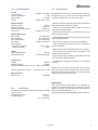
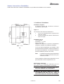
1.0 Speci• cations
Power:
Power Supply
Power consumption
Motor rating
Fuses
Measurements:
Measuring time
Measuring speed
SAPE arm working range
Resolution
Wheel dimensions:
Max. width
Max. diameter
Max. shaft weight
Rim width
Rim diameter:
-
Automatic / Manual
- SMART SONAR
Shaft:
Stub shaft diameter
Stub shaft length
Dimensions:
Weight
Shipping weight
Machine Dimensions H x W x D
Shipping dimensions (max)
Miscellaneous:
Noise level
2.0 Conditions
During use or long term storage, the conditions shou
ld
never ecxeed:
Temperature range
Humidity range
non-condensing
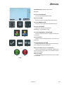
3.0 Introduction
Motorized wheel balancer that features extremely
fast
data entry, low cycle times with an improved user
interface making this a top choice for shops.
- Medium footprint motorized wheel balancer features
static and dynamic balancing modes.
- Features a touchscreen video monitor for easy to
read measurement results.
- Automatic mode selection by placing SAPE arm in
desired weight location.
- Laser guided weight placement for quick and accurate
tape weight placement.
- Sonar sensor measures rim width automatically.
- LED backlighting illuminates inside of wheel for
improved visibility.
- Split weight mode hides weight behind rim spokes
- Touchscreen facilitates faster navigation and
improved mode selection.
- Large stadium-style weight tray provides user with
easy access to storage pockets.
- Virtual Plane Imaging technology for unsurpassed
accuracy.
Always work in a clean area and with clean wheels.
First remove dirt and old weights from tires and rims.
That way proper mounting of the wheel and an optimal
balancing result can be achieved.
Application
The off-the-vehicle wheel balancer is designed for
dynamic and static balancing of passenger car and
light-truck wheels, that fall within the limits stated in
the technical speci! cations (F 1).
This is a high accuracy measuring device. Handle with care.
115VAC, 1ph, 60Hz
2,5 A
0,12 KW
(2x)IEC 127 T 6,3A
>6 sec.
<200 rpm
0–290 mm
0.05/0.25 oz (1/5 g)
20” (500 mm)
42” (1066 mm)
154 lbs (70 Kg)
3-20” (76-510mm)
8-25” / 8-32”
13-26”
40 mm
8.9 inch (225 mm)
286 lbs
353 lbs
70in x 59in x 45in
52.8in x 41.5in x 37in
<70 db(A)
3
2-122 °F
10-90%

6
EEWB334A
3-1
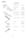
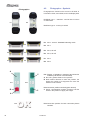
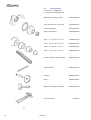
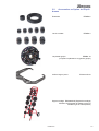
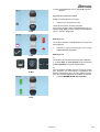
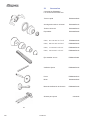
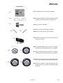
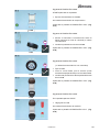
3.1 Accessories
Refer to Figure 3-1.
The standard accessories are:
Quick-Release Hub Nut EAA0263G66A
Rubber protector ring EAC0058D15A
Pressure cup EAC0058D07A
Presure disk EAC0058D08A
Cone, 87-137 mm / 3.4”-5.4” EAM0003J69A
Cone, 96-114 mm / 3.8”-4.5” EAM0005D25A
Cone, 71-99 mm / 2.8”-3.9” EAM0005D24A
Cone, 40-76 mm / 1.6”-3.0” EAM0005D23A
Standard 40mm Stub Shaft EAM0021D90A
Fastening Rod EAM0005D34A
Pin EAM0006G01A
Flange EAC0060G02A
User Calibration weight EAM0005D40A
Weight pliers 8-04250A

7
EEWB334A
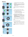
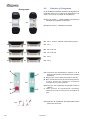
3.2 Optional Balancer Accessories
Spacer EEWB3-5
9 pc Collet Set EEWB3-4
Pin Plate Set EEWB3-1A
(includes 4 plates and 3 styles of studs)
Caliper for Rim Width EAA0247G21A
Storage Stand
EAK0309J20A (
Storage Stand
)
EEWB3-1A
(Pin Plate Set) and
EEWB3-4 (9-pc Collet Set)

8
EEWB334A
4-1
4-2
3
1
2
4
5
3a
6
8
2
1
9
7
3b
10
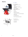
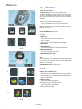
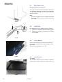
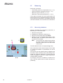
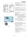
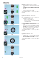
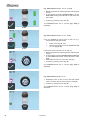
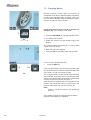
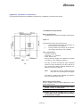
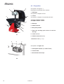
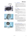
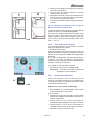
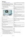
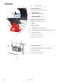
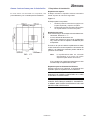
4.0 Layout
Refer to Figure 4-1
Functional description of the unit:
1. Display
Refer to Chapter “The Screen”.
2. Input panel
Refer to Chapter “Basic Commands”
3a.
Internal SAPE arm
3b.
External Detector - Sonar
4. Flange
5. Stub shaft
6. Weights compartments
7. Storage areas for cones and wheel weights
8. Wheel guard
9. Control pedal (Brake)
10. Laser weight placement indicator
Refer to Figure 4-2
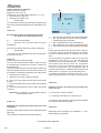
1. Main switch (ON/OFF)
2. Fuse holder
3. Power inlet

9
EEWB334A
4-3
4-4
3
21
4-5
4-3b
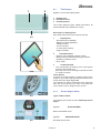
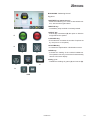
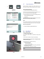
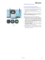
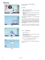
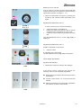
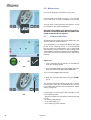
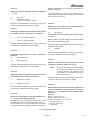
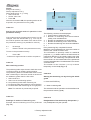
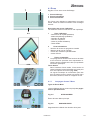
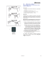
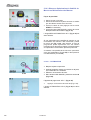
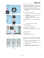
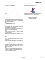
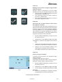
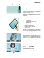
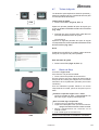
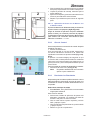
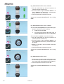
4.1 The Screen
Fig. 4-3 Screen with display ! elds
1 Display ! eld
2 Information ! eld
3 Commands ! eld
The screen displays inputs, helpful information, all
measured data and possible error codes.
Description of display ! elds
Each ! eld of the screen has a speci! c function.
1 Display ! eld
- Rim dimensions (editable).
- Balancing modes (editable).
- Inbalance value.
- List of Counters.
- C codes (User Codes).
- Help information.
2 Information ! eld
- Number of the installed program version.
- Measurements of the wheel being processed.
- Operating conditions icons.
- Error codes.
3 Commands ! eld
The pictographs illustrating basic and special
functions are located here.
Each key has an icon showing the speci! c function
it is used to retrieve.
Touch Screen
In the Touch Screen interface, in order to have a touch
response, you need to tap and release the area on the
screen with your ! nger (Fig. 4-3b).
The operator can hear a con! rmation tone, whenever
their own touch performs an action connected with
icons, buttons, text or images on the screen.
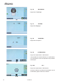
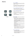
4.1.1 Screen Pages / Menu
Types of Menu Fields
The
Display ! eld shows the main Operating Screen
Pages:
Fig. 4-4 INTRO SCREEN
Basic screen/Main menu.
Fig. 4-5 RIM DATA ENTRY
Rim data input Screen.

10
EEWB334A
4-9b
4-9
4-8
4-7
4-6
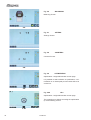
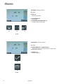
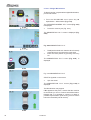
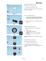
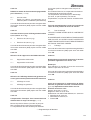
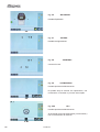
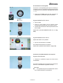
Fig. 4-6 BALANCING
Balancing Screen.
Fig. 4-7 SETTING
Settings Screen.
Fig. 4-8 COUNTERS
Counters Screen.
Fig. 4-9 OPTIMIZATION
Optimisation / weight Minimisation screen page.
It is possible to select whether an optimisation, a mi-
nimisation or an interrupted process restart has to be
carried out.
Fig. 4-9b OP.1
Optimisation / weight Minimisation screen page.
The measuring run allows accessing the optimisation
(or minimisation) process.

11
EEWB334A
4-10
1
2
3
4 5
6
7A 7B
8A 8B
9
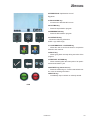
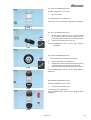
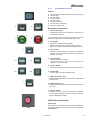
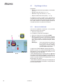
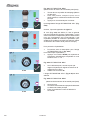
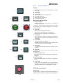
4.1.2 Basic Commands
Key pad
1
Menu Keys (one for each Menu ! eld)
2 ESC key
3 HELP key
4 START key
5 STOP key (emergency stop)
6 OK key (to con! rm)
Description of keys
1 Keys (example)
- Activate certain functions for the execution and con-
tinuation of a speci!
c operation of the cycle.
The function of menu keys is indicated by the relevant
symbols displayed on the monitor.
2 ESC key
- Switches back to the previous screen (status).
- Exits the C code procedures.
- Clears help texts and error messages.
3 HELP key
- Displays useful information that explains the ope-
rating condition and - in case of error messages
- provides help to solve the error.
4 START key
- Starts the measuring run. Press to start wheel rota-
tion, with the wheel guard down.
5 STOP key
- Immediately stops a wheel run already started.
6 OK key
- Con! rms the Menu option previously selected.
7 A/B Key mm / inch
- Switches the readings display between millimetres
and inches.
8 A/B Key g / oz
- Switches the readings display between grams and
ounces.
9 FINE key
- Activates the ! ne reading of the residual imbalances.
The operation of the key is timed and it automatically
returns to the basic display.
Electromechanical STOP
Figure 4-10
When
the Electromechanical Stop Button is pressed,
the wheel rotation is stopped.

12
EEWB334A
4-11
3
2
4 5
6
4-12
1
B CA
8
9
7
BA
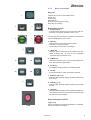
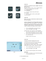
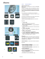
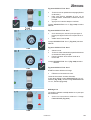
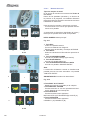
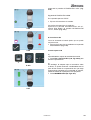
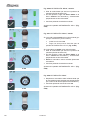
4.1.2.1 Menu Buttons
Types of menu ! elds
The Menu Keys are in the Commands Field.
Therefore,
depending on the position in the program,
the many Operating Screen Pages will in each case
show the Command keys needed for the functions
available.
To issue commands and select items:
- Touch the desired icons or keys on the screen.
Below are the meanings of the icons and keys selec-
table on the screen.
INTRO SCREEN “Main menu”
Fig. 4-11
1 ESC key
- Switches back to the previous screen.
- Exits C codes.
- Clears HELP texts and ERROR messages.
2 HELP key
- Selects HELP texts for the current function.
3 SETTINGS key
- Accesses the Settings screen (triple session).
4 BALANCING key
– Accesses the Balancing screen.
5 RIM DATA ENTRY key
- Accesses the “RIM DATA ENTRY” screen.
Note:
From this screen page, simply removing the measuring
arm causes an automatic switch to the “RIM DATA
ENTRY” screen page.
RIM DATA ENTRY “Rim data entry”
Fig. 4-12
6 EASY ALU TOGGLE key
- Changes the ALU mode suggested by the machine.
7 RESTART OPT/MIN key
- Allows restarting an optimisation/minimisation cycle
after the interruption.
8 VEHICLE key
- Allows the following selections:
MOTORCYCLE (A) VAN (B) CAR (C).
9 OPERATOR key
- Allows the following selections:
USER 1 (A) USER 2 (B)

13
EEWB334A
4-13
B
B
20
1817
A
A
BA
15
16
19
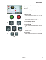
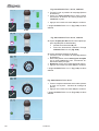
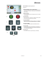
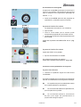
BALANCING “Balancing Screen”
Fig. 4-13
15A START key (starts the run)
- Starts the measuring run. Press to start wheel rota-
tion, with the wheel guard down.
15B STOP key
- Immediately stops a wheel run already started.
16 SPLIT key
- Selects (A) or deselects (B) the option to hide the
weight behind the spokes.
17 SPOKES key
– Each selection increases the number of spokes set
by one (from 3 to 15 spokes).
18 OPT/MIN key
– Accesses the Optimisation / Minimisation screen.
19 END key
- Activates the reading of the residual imbalances.
The operation of the key is timed and it automatically
returns to the basic display.
20 Key g / oz
- Enables the readings in grams (A) and ounces (B).

14
EEWB334A
22
25
23
4-14
4-15
26
24
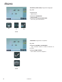
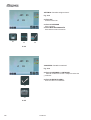
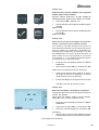
SETTINGS “Settings Screen”
Fig. 4-14
22 OK key
- Con! rms the action.
23 CONTINUE key
- To continue.
24 FURTHER INFORMATION key
- To obtain further information.
COUNTERS “Counters Screen”
Fig. 4-15
25 CONFIRMATION / CONTINUE key
- Allows the user to con! rm the action or acquire the
selection and continue.
26 RESET key
- To reset counters.

15
EEWB334A
4-16
27
30A
31
29
33
28
30B
32
34B34A
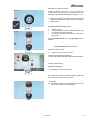
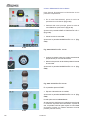
OPTIMIZATION “Optimisation Screen”
Fig. 4-16
27 BALANCING key
- Accesses the BALANCING screen.
28 OPT/MIN key
– Starts the Optimisation program
29 MINIMISATION key
- Starts the Minimisation program.
30 OPERATOR key
- Allows the following selections
USER 1 (A) USER 2 (B)
31 CONFIRMATION / CONTINUE key
- Allows the user to con! rm the action or acquire the
selection and continue.
32 BACK key
- Allows going back one step during execution of the
program.
33 RESTART OPT/MIN key
- Allows restarting after the interruption of an optimi-
sation/minimisation cycle.
34A START key (starts the run)
- Starts the measuring run. Press to start wheel rota-
tion, with the wheel guard down.
34B STOP key
- Immediately stops a wheel run already started.

16
EEWB334A
P3
P5
P7
P4
P6
P8
P11
P13
P12
P1
P2
A
A
B
C
C
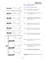
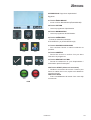
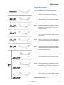
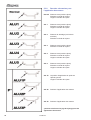
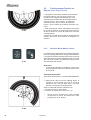
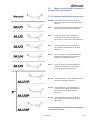
• Pictographs •
4.2 Pictographs – Symbols
Pictographs are viewed on the screen in all ! elds: In
i
nformation ! elds, menu ! elds, and in the display ! eld.
P1 Wheel type 1 – standard - nominal size in inches
or millimetres
P2 Wheel type 2 - motorcycle wheel
P3 Alu 0 - normal - Standard balancing mode
P4 Alu 1
P5 Alu 2,
Alu 2P
P6 Alu 3, Alu 3P
P7 Alu 4
P8 Alu 5
P11 Display of inbalance measured and direction
indicator (red arrows or arrows head)
A
No color: greater distance from position
B Red: rotation direction to reach the position, the
higher the number of lit segments the more the
wheel must be rotated.
P12 Correction position reached (green arrows)
C Green: compensation position reached, hold the
wheel in this position to apply the weight.
P13 C
orrection position for both correction planes
reached.

17
EEWB334A
P17
P16
P15
P14
P18
P19
P20 P21
P22 P23
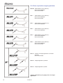
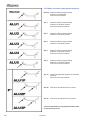
• Pictographs •
P14 Compensation run carried out.
P15 Start measuring run by pressing the START key
or closing the wheel guard.
P16 Set the Calibration weight.
P17 Provide mark on left tire side.
P18 Provide mark on right tire side.
P19 Fit tire on rim and infl ate to the specifi ed infl ation
pressure.
P20 Rotate rim until valve is exactly perpendicular to
and above the main shaft.
P21 Rotate wheel until valve is exactly perpendicular
to and above the main shaft.
P22 Readjust tire on rim until the mark coincides
precisely with the valve.
P23 Readjust tire on rim until the double mark coincides
precisely with the valve.

18
EEWB334A
4-17
4-18
4-19
4-19b
1
2
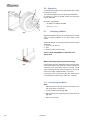
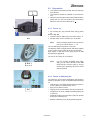
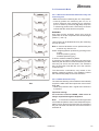
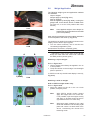
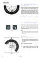
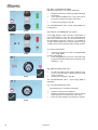
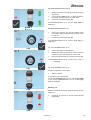
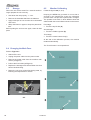
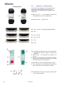
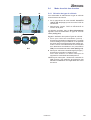
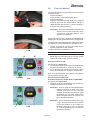
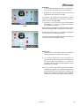
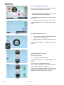
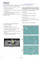
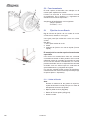
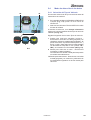
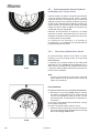
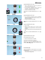
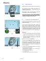
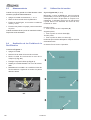
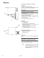
4.3 Main Shaft Lock
Fig. 4-17 Pedal of main shaft lock
The main shaft is locked when the pedal is depressed.
This facilitates tightening or loosening of the clamping
nut and retains the wheel in the correct position for
applying weights.
Note:
This lock is designed only to facilitate orientation
of the wheel and must not be used for braking the
main shaft.
4.4 SAPE Arm
Fig. 4-18 SAPE arm for distance and rim diameter
.
1 SAPE
arm, can be extended and hinged upwards.
2 SAPE disk to identify rim dimensions on a variety
of rim pro! les.
4.5 Sonar Sensor
On the outer side of the rim the machine has a So-
nar sensor to measure wheel width (outside of rim)
(Fig. 4-19).
The sonar has a tolerance of +/- 0.5’’.
4.6 Laser Pointer
Fig. 4-19b
T
he machine uses the Laser Pointer to indicate a
precise point for placing adhesive weights on the rim.

19
EEWB334A
4-20
4-21
4-10
4-22
3
2
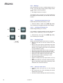
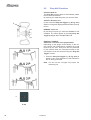
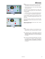
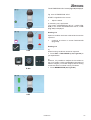
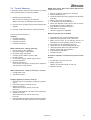
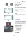
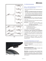
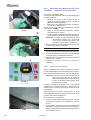
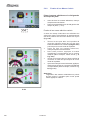
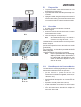
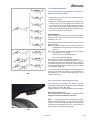
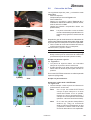
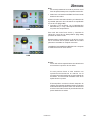
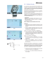
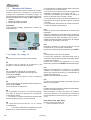
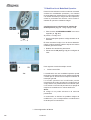
4.7 Help Information
Help information explains the current action and, in
the case of an error code, provides hints for remedy.
Display help information
— Press the HELP key (Fig. 4-10, Pos. 3).
The ! rst screen with help information appears, e. g. to
the screen RIM DATA INPUT (Fig. 4-20).
— Press the HELP key once more to display the next
screen with help information.
(if present)
The second screen with help information to the scree
n
RIM DATA INPUT (Fig. 4-21) appears.
Note:
On pressing the HELP key in the last screen with help
information the display jumps to the ! rst screen again.
Quit help information
— Press the ESC key (Fig. 4-10, Pos. 2).
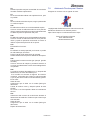
4.8 Stop Button
Refer to Figure 4-22.
T
o perform an immediate stop:
• Press the Stop button:
The electric motor brake is activated to stop wheel
rotation.
In the event the balancer stops unexpectedly:
Check to be sure all inputs were completed prior
to the balancing spin.
If all parameters are inputted correctly:
• Restart the machine:
turn off the unit
turn on the unit again.
• Using the proper procedure input the parameters
and rebalance the tire.
• If the unit does not function correctly,
WARNING: PREVENT ANY FURTHER USE OF THE
UNIT.
• Call service 800-225-5786.

20
EEWB334A
5-1
5-2
1
2
3
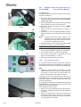
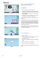
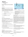
5.0 Operation
This chapter describes how to operate the unit in order
to balance a wheel.
The standard balancing runs will be described ! rst.
In chapter 5.4 and up special modes and functions
will be described.
Be sure to understand:
- All SAFETY PRECAUTIONS
- The unit, F 4.0.
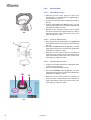
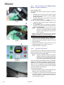
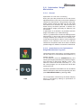
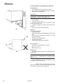
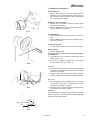
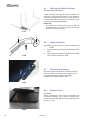
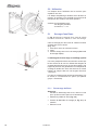
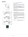
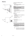
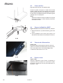
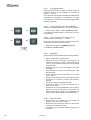
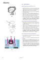
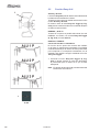
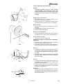
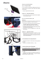
5.1 Clamping a Wheel
Fig. 5-1
Illustrates clamping a conventional car wheel
using a clamping adaptor on the pilot center of the
wheel.
Clamping adaptor to clamp pilot hole centered wheels
(Fig. 5-1)
1 Cone for car wheels
2 Rim
3 Quick nut with pressure cup
DO NOT USE A HAMMER TO TIGHTEN THE
QUICK NUT.
Wheel mounting requiring special tooling
A clad wheel must be centered properly from the back
side of the wheel using precision collets instead of a
centering cone. A precision collet is normally a dual
sided centering device with low tapers on each side
and has a length of approximately 1.5 inches
.
A centering cone can break off the tabs. See section
3.2 Optional Accessories (Pin Plate Set - Spacer).
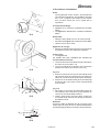
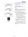
5.1.1
Unclamping the Wheel
Note:
While the jaws unclamp, hold the wheel so that it
will not tilt when unclamped.
• Lower the brake pedal (Fig. 5-2).
• Remove the quick–clamping nut from the chuck (3,
Fig. 5-1).
• Remove the wheel.
La page est en cours de chargement...
La page est en cours de chargement...
La page est en cours de chargement...
La page est en cours de chargement...
La page est en cours de chargement...
La page est en cours de chargement...
La page est en cours de chargement...
La page est en cours de chargement...
La page est en cours de chargement...
La page est en cours de chargement...
La page est en cours de chargement...
La page est en cours de chargement...
La page est en cours de chargement...
La page est en cours de chargement...
La page est en cours de chargement...
La page est en cours de chargement...
La page est en cours de chargement...
La page est en cours de chargement...
La page est en cours de chargement...
La page est en cours de chargement...
La page est en cours de chargement...
La page est en cours de chargement...
La page est en cours de chargement...
La page est en cours de chargement...
La page est en cours de chargement...
La page est en cours de chargement...
La page est en cours de chargement...
La page est en cours de chargement...
La page est en cours de chargement...
La page est en cours de chargement...
La page est en cours de chargement...
La page est en cours de chargement...
La page est en cours de chargement...
La page est en cours de chargement...
La page est en cours de chargement...
La page est en cours de chargement...
La page est en cours de chargement...
La page est en cours de chargement...
La page est en cours de chargement...
La page est en cours de chargement...
La page est en cours de chargement...
La page est en cours de chargement...
La page est en cours de chargement...
La page est en cours de chargement...
La page est en cours de chargement...
La page est en cours de chargement...
La page est en cours de chargement...
La page est en cours de chargement...
La page est en cours de chargement...
La page est en cours de chargement...
La page est en cours de chargement...
La page est en cours de chargement...
La page est en cours de chargement...
La page est en cours de chargement...
La page est en cours de chargement...
La page est en cours de chargement...
La page est en cours de chargement...
La page est en cours de chargement...
La page est en cours de chargement...
La page est en cours de chargement...
La page est en cours de chargement...
La page est en cours de chargement...
La page est en cours de chargement...
La page est en cours de chargement...
La page est en cours de chargement...
La page est en cours de chargement...
La page est en cours de chargement...
La page est en cours de chargement...
La page est en cours de chargement...
La page est en cours de chargement...
La page est en cours de chargement...
La page est en cours de chargement...
La page est en cours de chargement...
La page est en cours de chargement...
La page est en cours de chargement...
La page est en cours de chargement...
La page est en cours de chargement...
La page est en cours de chargement...
La page est en cours de chargement...
La page est en cours de chargement...
La page est en cours de chargement...
La page est en cours de chargement...
La page est en cours de chargement...
La page est en cours de chargement...
La page est en cours de chargement...
La page est en cours de chargement...
La page est en cours de chargement...
La page est en cours de chargement...
La page est en cours de chargement...
La page est en cours de chargement...
La page est en cours de chargement...
La page est en cours de chargement...
La page est en cours de chargement...
La page est en cours de chargement...
La page est en cours de chargement...
La page est en cours de chargement...
La page est en cours de chargement...
La page est en cours de chargement...
La page est en cours de chargement...
La page est en cours de chargement...
La page est en cours de chargement...
La page est en cours de chargement...
La page est en cours de chargement...
La page est en cours de chargement...
La page est en cours de chargement...
La page est en cours de chargement...
La page est en cours de chargement...
La page est en cours de chargement...
La page est en cours de chargement...
La page est en cours de chargement...
La page est en cours de chargement...
La page est en cours de chargement...
La page est en cours de chargement...
La page est en cours de chargement...
La page est en cours de chargement...
La page est en cours de chargement...
La page est en cours de chargement...
La page est en cours de chargement...
La page est en cours de chargement...
La page est en cours de chargement...
La page est en cours de chargement...
La page est en cours de chargement...
La page est en cours de chargement...
La page est en cours de chargement...
La page est en cours de chargement...
La page est en cours de chargement...
La page est en cours de chargement...
La page est en cours de chargement...
La page est en cours de chargement...
La page est en cours de chargement...
La page est en cours de chargement...
La page est en cours de chargement...
La page est en cours de chargement...
La page est en cours de chargement...
La page est en cours de chargement...
La page est en cours de chargement...
La page est en cours de chargement...
La page est en cours de chargement...
La page est en cours de chargement...
La page est en cours de chargement...
La page est en cours de chargement...
La page est en cours de chargement...
La page est en cours de chargement...
La page est en cours de chargement...
La page est en cours de chargement...
La page est en cours de chargement...
La page est en cours de chargement...
La page est en cours de chargement...
La page est en cours de chargement...
La page est en cours de chargement...
La page est en cours de chargement...
La page est en cours de chargement...
La page est en cours de chargement...
La page est en cours de chargement...
La page est en cours de chargement...
La page est en cours de chargement...
La page est en cours de chargement...
La page est en cours de chargement...
La page est en cours de chargement...
La page est en cours de chargement...
La page est en cours de chargement...
La page est en cours de chargement...
La page est en cours de chargement...
La page est en cours de chargement...
La page est en cours de chargement...
La page est en cours de chargement...
La page est en cours de chargement...
La page est en cours de chargement...
La page est en cours de chargement...
La page est en cours de chargement...
La page est en cours de chargement...
La page est en cours de chargement...
-
 1
1
-
 2
2
-
 3
3
-
 4
4
-
 5
5
-
 6
6
-
 7
7
-
 8
8
-
 9
9
-
 10
10
-
 11
11
-
 12
12
-
 13
13
-
 14
14
-
 15
15
-
 16
16
-
 17
17
-
 18
18
-
 19
19
-
 20
20
-
 21
21
-
 22
22
-
 23
23
-
 24
24
-
 25
25
-
 26
26
-
 27
27
-
 28
28
-
 29
29
-
 30
30
-
 31
31
-
 32
32
-
 33
33
-
 34
34
-
 35
35
-
 36
36
-
 37
37
-
 38
38
-
 39
39
-
 40
40
-
 41
41
-
 42
42
-
 43
43
-
 44
44
-
 45
45
-
 46
46
-
 47
47
-
 48
48
-
 49
49
-
 50
50
-
 51
51
-
 52
52
-
 53
53
-
 54
54
-
 55
55
-
 56
56
-
 57
57
-
 58
58
-
 59
59
-
 60
60
-
 61
61
-
 62
62
-
 63
63
-
 64
64
-
 65
65
-
 66
66
-
 67
67
-
 68
68
-
 69
69
-
 70
70
-
 71
71
-
 72
72
-
 73
73
-
 74
74
-
 75
75
-
 76
76
-
 77
77
-
 78
78
-
 79
79
-
 80
80
-
 81
81
-
 82
82
-
 83
83
-
 84
84
-
 85
85
-
 86
86
-
 87
87
-
 88
88
-
 89
89
-
 90
90
-
 91
91
-
 92
92
-
 93
93
-
 94
94
-
 95
95
-
 96
96
-
 97
97
-
 98
98
-
 99
99
-
 100
100
-
 101
101
-
 102
102
-
 103
103
-
 104
104
-
 105
105
-
 106
106
-
 107
107
-
 108
108
-
 109
109
-
 110
110
-
 111
111
-
 112
112
-
 113
113
-
 114
114
-
 115
115
-
 116
116
-
 117
117
-
 118
118
-
 119
119
-
 120
120
-
 121
121
-
 122
122
-
 123
123
-
 124
124
-
 125
125
-
 126
126
-
 127
127
-
 128
128
-
 129
129
-
 130
130
-
 131
131
-
 132
132
-
 133
133
-
 134
134
-
 135
135
-
 136
136
-
 137
137
-
 138
138
-
 139
139
-
 140
140
-
 141
141
-
 142
142
-
 143
143
-
 144
144
-
 145
145
-
 146
146
-
 147
147
-
 148
148
-
 149
149
-
 150
150
-
 151
151
-
 152
152
-
 153
153
-
 154
154
-
 155
155
-
 156
156
-
 157
157
-
 158
158
-
 159
159
-
 160
160
-
 161
161
-
 162
162
-
 163
163
-
 164
164
-
 165
165
-
 166
166
-
 167
167
-
 168
168
-
 169
169
-
 170
170
-
 171
171
-
 172
172
-
 173
173
-
 174
174
-
 175
175
-
 176
176
-
 177
177
-
 178
178
-
 179
179
-
 180
180
-
 181
181
-
 182
182
-
 183
183
-
 184
184
-
 185
185
-
 186
186
-
 187
187
-
 188
188
-
 189
189
-
 190
190
-
 191
191
-
 192
192


Snap-On EEWB334A Operation Instructions Manual
- Taper
- Operation Instructions Manual
dans d''autres langues
- English: Snap-On EEWB334A
- español: Snap-On EEWB334A
Documents connexes
Autres documents
-
 Prime-Line L 5786 Mode d'emploi
-
 Snap-on Equipment JohnBean B2000P Series Manuel utilisateur
-
Hofmann geodyna 7300 Mode d'emploi
-
GYS METER 052093 Electronic Measurement Device Manuel utilisateur
-
-
CLAS EQ 0500BL Le manuel du propriétaire
-
 Grip 9118746 Le manuel du propriétaire
-
HWM A173 Mode d'emploi
-
HWM PCorr Mode d'emploi
-
HWM-Water Ltd HWM-Water Ltd SonicSens 3 Monitor Networks Manuel utilisateur


