
REV 3 - 1407091450
L-C2-005
1
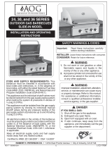
SAFETY WARNINGS & CODES
INSTALLER: Leave these instructions with consumer.
CONSUMER: Retain for future reference.
INSTALLATION AND OPERATING
INSTRUCTIONS
Important: READ THESE INSTRUCTIONS CAREFULLY BEFORE STARTING INSTALLATION
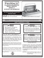
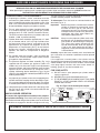
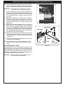
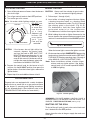
REGAL I DROP-IN
SERIES 34
OUTDOOR GAS BARBECUE
(Unit with optional backburner & oven shown)
DANGER
IF YOU SMELL GAS:
1. Shut off the gas to the appliance.
2. Extinguish any open fl ame.
3. Open lid if equipped with an oven.
4. If odor continues, keep away from the
appliance, and immediately call your gas
supplier or fi re department.
WARNING
1. Do not store or use gasoline, or other
fl ammable vapors and liquids, in the
vicinity of this or any other appliance.
2. A propane cylinder not connected for use
shall not be stored in the vicinity of this
or any other appliance.
Robert H. Peterson Co. • 14724 East Proctor Avenue • City of Industry, CA 91746
CODE AND SUPPLY REQUIREMENTS: This
barbecue must be installed in accordance with local
codes and ordinances or, in the absence of local
codes, with either the current National Fuel Gas
Code (ANSI Z223.1NFPA 54), Natural Gas and
Propane Installation Code (CSA B149), or Propane
Storage and Handling Code (CSA B149.2).
This appliance and its individual shutoff valves must
be disconnected from the gas supply piping system
when testing the system at pressures in excess of
½ psig (3.5 kPa).
This appliance must be isolated from the gas supply
piping system by closing its individual manual
shutoff valves during any pressure testing of the
gas supply system at pressures up to and including
½ psig (3.5 kPa).
Improper installation, adjustment, alteration,
service, or maintenance can cause injury or
property damage. Refer to this manual. For
assistance or additional information consult
a qualifi ed, professional installer, service
agency, or the gas supplier.
All electrical outlets in the vicinity of the barbecue
must be properly grounded in accordance with local
codes or, in the absence of local codes, with the
National Electrical Code, ANSI/NFPA 70, or the
Canadian Electrical Code, CSA C22.1, whichever
is applicable.
CAUTION: Keep all electrical supply cords and
fuel supply hoses away from any
heated surface.
Certifi ed to ANSI: Z21.58
WARNING

REV 3 - 1407091450
L-C2-005
2
AVERTISSEMENTS ET CODES DE SÛRETÉ
INSTALLATEUR : Laissez ces instructions avec le
consommateur.
CONSOMMATEUR : Maintenez pour la future
référence.
INSTALLATION ET CONSIGNES
D’UTILISATION
Important: LISEZ CES INSTRUCTIONS SOIGNEUSEMENT AVANT DE COMMENCER L’INSTALLATION
BARBECUE EXTÉRIEUR De GAZ
De la SÉRIE 34 MAJESTUEUX De I
DROP-IN
La photo montre l’unité avec le
backburner et le four facultatifs.
Robert H. Peterson Co. • 14724 East Proctor Avenue • City of Industry, CA 91746
DANGER
SI VOUS SENTEZ LE GAZ :
1. Coupez le gaz à l’appareil.
2. Éteignez-vous n’importe quelle fl amme nue.
3. Ouvrez le couvercle si équipé d’un four.
4. Si l’odeur continue, gardez loin de l’appareil,
et appelez immédiatement votre département
de fournisseur ou de feu de gaz.
AVERTISSEMENT
1. Ne stockez pas ou n’employez pas
l’essence, ou d’autres vapeurs et liquides
infl ammables, à proximité de ceci ou
d’aucun autre appareil.
2. Un cylindre de propane non relié pour
l’usage ne sera pas stocké à proximité
de ceci ou d’aucun autre appareil.
CONDITIONS DE CODE ET
D’APPROVISIONNEMENT : Ce barbecue doit être
installé selon des codes et des ordonnances locaux
ou, en l’absence des codes locaux, avec le code
national courant de gaz de carburant (norme ANSI
Z223.1NFPA 54), gaz naturel et code d’installation
de propane (CSA B149), ou stockage de propane
et le code de manipulation (CSA B149.2).
Cet appareil et ses différents robinets d’isolement
doivent être démontés du système siffl ant d’offre
de gaz en examinant le système aux pressions
au-dessus du ½ psig (kPa 3.5).
Cet appareil doit être isolé dans le système siffl ant
d’offre de gaz par fermeture ses différents robinets
d’isolement manuels pendant tous les essais
sous pression du circuit d’alimentation de gaz aux
pressions jusques et y compris le ½ psig (kPa 3.5).
L’installation inexacte, l’ajustement, le
changement, le service, ou l’entretien
peuvent causer des dommages ou des dégats
matériels. Référez-vous à ce manuel. Pour
l’aide ou l’information additionnelle consultez
un installateur qualifié et professionnel,
l’agence de service, ou le fournisseur de gaz.
Certifi é à la norme ANSI : Z21.58
AVERTISSEMENT
Toutes les sorties électriques à proximité du
barbecue doivent être correctement fondues selon
des codes locaux ou, en l’absence des codes locaux,
avec Code électrique national, ANSI/NFPA 70,
ou le code électrique canadien, CSA C22.1, celui
qui est applicable.
ATTENTION: Maintenez tous les cordes
d’alimentation électrique et tuyaux
d’approvisionnement en carburant
partis de n’importe quelle surface
de chauffage.

REV 3 - 1407091450
L-C2-005
TABLE OF CONTENTS
3
1 SAFETY WARNINGS & CODES
3 TABLE OF CONTENTS
5 PARTS LIST
6 FIRE MAGIC REGAL I DROP-IN SERIES (w/ BACKBURNER) PARTS LIST
7 FIRE MAGIC REGAL I DROP-IN BACKBURNER & OVEN PARTS LIST (WHERE FITTED)
8 MODEL SPECIFICATIONS
8 BUILT-IN GRILL DIMENSIONS TABLE
9 INSTALLATION REQUIREMENTS
10 ENSURING PROPER COMBUSTION AIR AND COOLING AIRFLOW
10 GAS-SUPPLY PLUMBING REQUIREMENTS
11 ENCLOSURE REQUIREMENTS
11 NATURAL GAS INSTALLS
11 PROPANE GAS INSTALLS (HOUSEHOLD & CYLINDER)
11 WHEN A PROPANE CYLINDER IS USED
13 SAFE USE & MAINTENANCE OF PROPANE GAS CYLINDERS
14 INSTALLATION
15 CHECKING AND CONVERTING GAS TYPE
15 CHECKING AND CONVERTING THE REGULATOR
16 CHECKING/CONVERTING THE BURNER ORIFICES
18 AIR SHUTTER ADJUSTMENT
18 MAIN BURNER AIR SHUTTER ADJUSTMENT
18 BACKBURNER AIR SHUTTER ADJUSTMENT
19 BARBECUE SAFETY INFORMATION & MAINTENANCE
19 DRIP COLLECTION SYSTEM
21 LIGHTING (IGNITION) INSTRUCTIONS
21 ELECTRONIC LIGHTING
21 MANUAL LIGHTING
22 ROTISSERIE INSTRUCTIONS
23 ACCESSORIES
24 CARE & CLEANING
25 TROUBLESHOOTING
25 REPLACING THE IGNITOR BATTERY
26 WARRANTY

REV 3 - 1407091450
L-C2-005
4
AVERTISSEMENTS
Avertissements généraux :
• Ce barbecue est pour ultilisation à l’extérieur seulement. Si l’appareil est entreposé à l’intérieur,
enlever les bouteilles et les laisser à l’extérieur.
• Ne pas ranger le gril immédiatement aprés l’avoir utilisé. le laisser refroidir avant de le déplacer
ou de la ranger. Le non respect de cette mesure de sécurité pourrait entraîner un incendie
causant des dommages à la propriété, des blessures ou la mort.
• Ne pas utiliser cet appareil sous une surface combustible.
• Ne pas utiliser cet appareil sous un auvent. Le non respect de cette mesure de sécurité pourrait
entraîner un incendie ou des blessures.
• Dégagement minimal entre les parois latérales et l’arriére de l’appareil et la construction
combustible (45.7 cm à partir des parois latérales et 45.7cm à partir de l’arriére).
• Le régulareur de pression de gaz prévu avec cet appareil de cuisson à gaz pour l’extérieur
doit être utilisé. Ce régulateur est réglé pour une pression de sortie de 5 pouces de colonne
de l’eau pour le gaz naturel, et 10 pouces pour le propane.
• LE RÉGULATEUR INCLUS D’APPAREILS EST ÉVALUÉ POUR LE MAXIMUM DE 1/2 (LIVRES
PAR POUCE CARRÉ). SI VOTRE OFFRE DE GAZ EST 1/2 PLUS GRAND QUE (LIVRES
PAR POUCE CARRÉ), UN RÉGULATEUR ADDITIONNEL DOIT ÊTRE INSTALLÉ AVANT LE
BARBECUE. VOIR LA SECTION DE CONDITIONS D’OFFRE DE GAZ POUR LA PRESSION
APPROPRIÉE D’OFFRE DE GAZ.
• Ne couvrez jamais la surface entière de cuisine ou de gril de gauffreuses ou de casseroles.
La surchauffe se produira et les brûleurs ne seront pas très performants quand la chaleur de
combustion est emprisonnée au-dessous de la surface à cuire.
• Ne pulvérisez jamais l’eau sur une unité chaude de gaz, comme ceci peut endommager des
composants de porcelaine ou de fer de fonte.
Avertissements de propane :
• Une fuite de GPL peut causer une incendie ou une explosion si enfl ammée entraînant des
blessures corporelles graves ou la mort.
• Communiquez avec le fournisseur de GPL pour les réparations ou pour disposer de qules
bouteille ou du GPL non utilisé.

REV 3 - 1407091450
L-C2-005
5
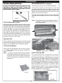
PARTS LIST
Replacement parts can be ordered
from your local Fire Magic dealer.
Item Description
1. TOP PANEL (STAINLESS STEEL)
or TOP PANEL (PORCELAIN)
2. 18"X10" COOKING GRID (STAINLESS STEEL)
or 18"X10" COOKING GRID (PORCELAINIZED CAST IRON)
3. FLAVOR GRID 7"
4. FLAVOR GRID 10" (2)
5. BURNER (6)
6. AIR SHUTTER SPRING (6)
7. AIR SHUTTER (6)
8. ORIFICE (NAT GAS)
or ORIFICE (PROPANE GAS)
9. VALVE MANIFOLD W/ VALVE & REGULATOR
10. BURNER MANIFOLD (3)
11. 15.5" FLEX TUBE ASSEMBLY
12. 34" FLEX TUBE ASSEMBLY
13. 48" FLEX TUBE ASSEMBLY
14. CONTROL KNOB (3)
15. IGNITOR ASSEMBLY
16. GROUND WIRE
17. ELECTRODE COLLECTOR ASSEMBLY
18. DRIP TRAY
19. DISPOSABLE DRIP TRAY LINER
1
15
5
7
8
10
6
11
12
13
9
17
14
16
3
4
18
19
2

REV 3 - 1407091450
L-C2-005
6
FIRE MAGIC REGAL I DROP-IN SERIES (w/ BACKBURNER) PARTS LIST
Item Description
1. OVEN HOOD W/ BACKBURNER (S.S. OR PORCELAIN)
2. BACKBURNER ASSEMBLY
3. TOP PANEL (STAINLESS STEEL)
or TOP PANEL (PORCELAIN)
4. 18"x10" COOKING GRID (PORCELAINIZED CAST IRON) (3)
or 18"X10" COOKING GRID (STAINLESS STEEL) (3)
5. FLAVOR GRID 7" (1)
6. FLAVOR GRID 10" (2)
7. BURNER (6)
8. AIR SHUTTER SPRING (6)
9. AIR SHUTTER (6)
10. ORIFICE (NAT GAS)
or ORIFICE (PROPANE GAS)
Item Description
11. BACKBURNER ORIFICE (NAT GAS)
or BACKBURNER ORIFICE (PROPANE GAS)
12. BURNER MANIFOLD (3)
13. VALVE MANIFOLD W/ VALVE & REGULATOR
14. 48" FLEX TUBE ASSEMBLY
15. 34" FLEX TUBE ASSEMBLY
16. 15.5" FLEX TUBE ASSEMBLY
17. ELECTRODE COLLECTOR ASSEMBLY
18. BACKBURNER KNOB (1)
19. CONTROL KNOB (3)
20. IGNITOR GENERATOR
21. DRIP TRAY
22. DISPOSABLE DRIP TRAY LINER
1
2
3
4
5
6
7
8
9
10
11
12
13
15
16
17
18
19
20
21
22
IMPORTANT
This Fire Magic oven
and backburner are fully
pre-assembled and tested at
the factory.
DO NOT attempt to remove
the oven and backburner
(optional) from the
barbecue prior to or during
installation or damage to
the connecting gas line and
ignitor wiring may occur.
The plastic straps that
secure the oven (optional)
to the barbecue unit must
be removed and discarded
prior to lighting.
14

REV 3 - 1407091450
L-C2-005
7
PAL NUT
OVEN
EL-34, ELBOW
& ORIFICE
IGNITOR
ELECTRODE
WIRE
FIRE MAGIC REGAL I DROP-IN BACKBURNER & OVEN PARTS LIST (WHERE FITTED)
PARTS INCLUDED WITH THE BACKBURNER ASSEMBLY ARE INSIDE THE BROKEN LINE
EXPLODED VIEW OF BACKBURNER ASSEMBLY
Important: Your Fire Magic barbecue,
oven and backburner (where
fi tted) are fully pre-assembled
and tested at the factory.
Do not attempt to remove the oven and backburner
from the barbecue prior to or during installation.
Damage to the connecting gas line and ignitor
wiring may occur.
The plastic straps that secure the oven to the
barbecue unit should be removed and discarded
prior to lighting.
Item
No.
Description
1. Rotisserie motor with
mounting bracket attached
2. Spit prongs
3. Handle
4.
Spit rod
5
/
8
" hex
5. Counterbalance
6. Spit bracket
Oven
Pal nut
El-34, elbow
& orifi ce
Ignitor
electrode
wire
or Orifice, NG
Backburner assembly
Screw, 10-32 x 3/8”,
stainless steel
Backburner cover
4199-69
Electrode double rod
w/electrode
Air shutter &
Adj. screw
3030-01
Backburner gas line
w/compression nuts
& sleeves
3730-02
Oven lid stop
bumper (pair)
3/4” Pal nut
4732-08
Mounting bracket
4732-09
Woodchip smoker tray
3/4” Pal nut
EL-34
Elbow (lid stop)
4732-07
Electrode
wire
Orifice, LP
5
4
1
3
6
Mounting
bracket
2

REV 3 - 1407091450
L-C2-005
8
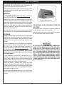
Important: FOR YOUR SAFETY, you must provide openings in the island enclosure for drainage, replacement air, and
cross-ventilation of any storage area exposed to possible leakage from gas connections, the unit, or propane
bottles. See the ENCLOSURE REQUIREMENTS section for details.
An access panel/door is required to allow for ease of access to drip tray and all connections (right side of grill).
MODEL SPECIFICATIONS TABLE
Table 1
Main burner BTU per pair
N/P orifi ce drill size
22,000 x 3
#52/#61
Backburner BTU
†
N/P orifi ce drill size
22,000
#42/#54
Backburner Air Shutter
†
N/P
5
/8" gap
7
/16" gap
Optional Regal insulating liner model #
3270-50
A Countertop to unit bottom cut-out* 18"
B Side to side non-combustible cut-out* 41
1
/
2
"
C Front to back non-combustible cut-out* 20
1
/
2
"
*
If using an insulating liner consult liner instructions for counter cut-out dimensions.
†
If equipped
MODEL SPECIFICATIONS
STUB OUT GAS PIPE
ANYWHERE IN THIS AREA
BACK
5"
5"
41
1
/2"
C
B
Fig. 8-1
COUNTER TOP
REARFRONT
Gas stub
A
5"
Fig. 8-2
Model
Height Width Depth
(Top to bottom) (Left to right) (Front to back)
Hanger to top
(with oven)
Hanger to
hanger
(F)
Maximum
depth
(G)
Open
(D)
Closed
(E)
Regal I
20
3
/8" 15
1
/4" 45" 26
1
/2"
BUILT-IN GRILL DIMENSIONS TABLE
D
E
F
G
Fig. 8-3

REV 3 - 1407091450
L-C2-005
9
This grill is designed for outdoor use only. DO NOT use this grill
inside a building, garage, enclosed area, or under an unprotected
overhead combustible construction. See the EXHAUST REMOVAL
section on the following page for details on installing under a patio
roof. DO NOT use this grill in or on a recreational vehicle or boat.
Important: If installing this grill in a combustible surround,
the correct R.H. Peterson insulating liner must
be used.
Important: Refer to the information below to ensure all
required clearances are met.
The grill must have a minimum clearance of 18" from
combustible materials/items AT ALL TIMES.
For the minimum clearances between the grill and any side or rear
walls, your setup must fall within one (or more) of the following:
A. Clearance between grill and strictly non-combustible wall
(i.e. brick wall, see Fig. 9-1)
• The grill must have a minimum of 4" right, left, and rear
clearance from any non-combustible wall.
(To allow for proper ventilation and prevent dangerous
overheating.)
B. Clearance between grill and a protected combustible wall
(i.e. a non-combustible wall in front of a combustible wall to
serve as a barrier. This can be accomplished by brick, or
a metal stud fi nished with non-combustible substrate, see
Fig. 9-2)
• The grill must have a minimum of 14" right, left, and rear
clearance from the protected combustible wall.
(The 4" non-combustible material plus an additional 10"
clearance between the grill and protected wall.)
C. Clearance between grill and combustible wall
• The grill must have a minimum of 18" right, left, and rear
clearance from any combustible wall (see Fig. 9-3).
Backsplash (if applicable)
If a non-combustible backsplash exists, it must have a minimum
of a 4" clearance from the rear of the grill (to allow for proper
ventilation and prevent dangerous overheating). See Fig. 9-4.
Important: This 4" backsplash clearance must fi rst be met prior
to any non-combustible walls beginning behind it.
Fig. 9-1 Clearance 'A' Diagram
Fig. 9-2 Clearance 'B' Diagram
Fig. 9-3 Clearance 'C' Diagram
Non-combustible
Min.
4"
(Clearance required for
right, left, and rear)
Min.
14"
Non-combustible
substrate
Non-combustible 4"
Combustible
Min.
18"
(Clearance required for
right, left, and rear)
(Clearance required for
right, left, and rear)
Fig. 9-4 Backsplash clearance
Non-combustible
Backsplash
Min.
4"
Combustible
INSTALLATION REQUIREMENTS

REV 3 - 1407091450
L-C2-005
10
This is a drop-in type unit designed to fi t into countertop
enclosures. The top panel of the unit is removable for
gas hookup, servicing and burner adjustment.
The top panel MUST remain removable for servicing
(see PARTS LIST).
Note: This unit should be installed so that it can be
removed at a later date if factory service is
required. Any protrusion into the barbecue
enclosure may obstruct the frame and prevent
the unit from dropping into place (see GAS
SUPPLY PLUMBING REQUIREMENTS).
ENSURING PROPER COMBUSTION AIR AND
COOLING AIRFLOW
Proper airfl ow (Fig. 10-1) MUST be maintained for the
grill to perform as it was designed. If airfl ow is blocked,
overheating and poor combustion will result. Do not block
the air inlet around the inside edges of the top panel or
more than 75% of the cooking grid surface with pans
or griddles.
EXHAUST REMOVAL
If installed or used under a patio roof, the cooking grid
area must be fully covered by an exhaust hood with a
vent. An exhaust fan with a rating of 1,000 CFM (cubic
feet per minute) or more may be necessary to effectively
remove smoke and other cooking by-products from
the area under the hood. Fire Magic Vent Hoods are
available to meet this requirement. This grill must
not be used under unprotected overhead combustible
construction. THIS UNIT MUST NOT BE LOCATED IN
A FULLY ENCLOSED AREA OF ANY KIND.
GAS-SUPPLY PLUMBING REQUIREMENTS
For natural gas or a household propane system, rigid
1
/
2
" or
3
/
4
" black steel pipe or local code-approved pipe
is required to conduct the gas supply to the unit. Contact
your local gas supplier. Connect this pipe to a required
C.S.A.-approved stainless-steel fl ex connector. DO NOT
use a rubber hose within the grill enclosure. Apply
only joint compounds that are resistant to all gasses to
all male pipe fi ttings except fl are fi ttings. Make sure to
tighten every joint securely.
The gas supply pipe should enter from the fl oor, or
from the back or side wall in the right rear corner of
the barbecue enclosure, behind the valve control zone.
This pipe should terminate with a
1
/
2
" male pipe thread,
situated within 12" of the countertop and no more
than 5" from the back and side walls. See the MODEL
SPECIFICATIONS section for details.
Note: If
1
/
2
" pipe is used with natural gas, it should
be no longer than 20'.
Important: An external valve (with a removable
key) in the gas line is necessary for
safety when the grill is not in use. It also
provides for convenient maintenance.
CAUTION: Wind blowing into or across the rear
oven lid vent (if applicable) can cause
poor performance and/or dangerous
overheating. Orient the grill so that the
prevailing wind blows toward the front of
the grill.
GAS SUPPLY AND MANIFOLD PRESSURES:
For natural gas - normal 7" (17.78 cm) water column
(w.c.), minimum 5" (12.7 cm), maximum 10
1
/
2
" (26.7
cm). For propane gas - normal 11" w.c., minimum 10"
(25.4 cm), maximum 13" (33 cm).
INSTALLATION REQUIREMENTS (CONT.)
Fig. 10-1 - Ventilation Diagram
Vents at
Cylinder Le

REV 3 - 1407091450
L-C2-005
11
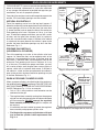
FOR YOUR SAFETY, you must provide the openings listed
below for drainage, replacement air, and cross-ventilation
of any storage area exposed to possible leakage from gas
connections, the unit, or propane cylinders.
One side of the enclosure can be left completely open to the
outside, OR 4 ventilation openings must be created:
NATURAL GAS INSTALLS
Two of the openings are to be at the top level (approx. 4"
below the countertop) and on opposite walls of the enclosure.
2 more openings must be at the fl oor level (no more than
5" above the fl oor) and on opposite sides of the enclosure.
Each opening must have a minimum of 10 sq. in. of free
area. To achieve the proper ventilation, you may drill a series
of holes, omit the grout from masonry joints, or replace a
brick with a hardware cloth screen. If the fl oor in the cabinet
is raised and the space beneath the cabinet is open to the
outside, the lower ventilation openings may be in the fl oor.
Reference Fig. 11-1.
PROPANE GAS INSTALLS
(HOUSEHOLD & CYLINDER)
Two of the openings are to be at the cylinder valve level
(approx. 16" above the fl oor) and on opposite walls of the
enclosure. 2 more openings must be at the fl oor level (no
more than 5" above the fl oor) and on opposite sides of the
enclosure. Each opening must have a minimum of 10 sq.
in. of free area. To achieve the proper ventilation, you may
drill a series of holes, omit the grout from masonry joints, or
replace a brick with a hardware cloth screen. If the fl oor in
the cabinet is raised and the space beneath the cabinet is
open to the outside, the lower ventilation openings may be
in the fl oor. Reference Fig. 11-1.
WHEN A PROPANE CYLINDER IS USED
When a propane cylinder is installed inside of the enclosure,
the guidelines below MUST be followed. FAILURE TO DO SO
MAY CAUSE DAMAGE TO YOUR UNIT AND/OR PERSONAL
INJURY. Reference Fig. 11-2 for an example.
• Only a C.S.A. listed stainless steel connector can be
connected to the grill.
• The regulator/hose assembly coming from the propane
cylinder can only be connected to the above mentioned
grill fl ex connector. DO NOT connect the regulator/
hose assembly directly to the grill. An adapter will
be required.
• A heatshield must be installed to protect the regulator/
hose assembly and propane cylinder valve.
• Fire Magic offers a propane cylinder door with tank
tray to meet the cylinder install requirements. See
Fig. 11-3.
Fig. 11-2 Propane cylinder orientation
Fig. 11-1 Ventilation detail
Nat. gas
installs
(repeat for
opposite
side)
Fig. 11-3 Optional Fire Magic door w/ tank tray
Adapter
L.P. gas
installs
(repeat for
opposite
side)
Grill
C.S.A. listed
stainless steel
fl ex connector
Heatshield
Regulator/
hose
assembly
L.P.
cylinder
Cylinder & regulator/
hose assembly
protected by heatshield
Equipped with
adapter for hose
assembly and
fl ex connector
ENCLOSURE REQUIREMENTS

12
U
L
Fig. 12-1 type coupleur rapide de fi l de point culminant d’I
Valve
de
décompression
QCC
Type 1
Valve
Ajustage de précision
en laiton de fi l de
point culminant
Indicateur
de niveau
de liquide
(facultatif)
Écrou de main avec le
fi l de point culminant.
Régulateur
Passage
Tuyau
Volant de commande
main dans le sens des aiguilles d’une montre pour engager les
fi ls et pour serrer jusqu’à ce que douillettement. L’utilisation des
pinces ou de la clé ne devrait pas être nécessaire. Seulement
le propane marqué par cylindres doit être employé.
Pour débrancher: Tournez l’écrou de main dans le sens
contraire des aiguilles d’une montre jusqu’à isolé (fi g. 12-1).
Important: Avant d’employer le gril, et ensuite chaque
fois que le cylindre est enlevé et rattaché,
examinez tous les raccordements pour déceler
les fuites. Arrêtez les valves de gril et ouvrez
la valve principale de cylindre, puis vérifi ez
les raccordements avec de l’eau savonneux.
Réparez toutes les fuites avant d’allumer le gril.
ATTENTION: Tournez toujours la valve principale de cylindre
de propane au loin après chaque utilisation,
et avant de déplacer le gril et le cylindre, ou
débrancher l’accouplement. Cette valve doit
rester fermée et le cylindre a débranché alors
que l’appareil n’est pas en service, quoique
l’écoulement de gaz soit arrêté par un dispositif
de sûreté quand le coupleur est débranché.
Inspectez soigneusement l’ensemble de tuyau chaque fois
avant que le gaz soit allumé. Un tuyau fi ssuré ou effi loché doit
être immédiatement remplacé.
Si l'appareil est stocké à l'intérieur, le cylindre doit être disconnected
et a enlevé. Des cylindres Disconnected doivent être stockés
dehors, hors de la portée des enfants, avec les prises de valve
fi letées étroitement installées, et ne doivent pas être stockés dans
un bâtiment, le garage, ou n'importe quel autre secteur inclus.
POUR VOTRE SÛRETÉ
a. Ne stockez pas un cylindre de gaz disponible de propane
dessous ou ne vous approchez pas de cet appareil.
b. Ne remplissez jamais cylindre au delà de 80 pour cent de
plein.
c. SI L’INFORMATION DANS “A” ET “B” N’EST PAS SUIVIE
EXACTEMENT, UN FEU CAUSANT LA MORT OU DES
DOMMAGES SÉRIEUX PEUT SE PRODUIRE.
IMPORTANT POUR VOTRE SÛRETÉ
LISEZ ET SUIVEZ TOUS LES AVERTISSEMENTS ÉQUIPÉS DE VOTRE CYLINDRE DE GAZ DE PROPANE.
En actionnant cet appareil avec un cylindre de gaz de propane ON DOIT observer ces instructions et avertissements.
LE MANQUE DE FAIRE AINSI PEUT AVOIR COMME CONSÉQUENCE UNE INCENDIE OU UNE EXPLOSION SÉRIEUSE.
CYLINDRE ET CONDITIONS ET
CARACTÉRISTIQUES DE CONNECTEUR
a. Des cylindres et les valves de gaz de propane doivent être
maintenus en bon état et doivent être remplacés s’il y a
des dommages évidents au cylindre ou à la valve.
b. Ce gril, une fois utilisé avec un cylindre, devrait être relié à
un gallon de la norme 5 (20lb.) cylindre de gaz de propane
équipé d’un OPD (remplissez au-dessus du niveau le
dispositif d’empêchement). L’OPD a été exigé sur tous les
cylindres vendus depuis octobre 1.1998 pour empêcher le
remplissage excessif.
c. Les dimensions de cylindre devraient être approximativement
12"(30.5cm) de diamètre et 18" (45.7cm) hauts. Des
cylindres doivent être construits et marqués selon les
caractéristiques pour des cylindres de gaz de propane du
département des ETATS-UNIS du transport (D.O.T.) ou
le niveau national du Canada, du CAN/CSA-B339, des
cylindres, des sphères et des tubes pour le transport des
marchandises dangereuses.
d. Le cylindre doit inclure un collier pour protéger la valve
de cylindre et le circuit d’alimentation de cylindre doit être
assuré le retrait de vapeur.
e. Le montage du régulateur de pression et le fl exible (Fig. 12-1)
fourni avec cet appareil au gaz en plein air (modèles au
propane seulement) doit être utilisé. Assemblées d'origine et
régulateur de pression et le tuyau de remplacement doivent
être ceux spécifi és par le fabricant pour le raccordement d'un
dispositif de cylindre de liaison identifi ée comme de type I par
le 21.58-2005/CGA ANSI Z 1.6 à 2005 (voir liste des pièces
pour les informations de commande).
f. La valve de cylindre de gaz de propane doit être équipée
d’un dispositif d’accouplement de raccordement de
cylindre, décrit comme type I dans la norme défi nie dans le
e. de paragraphe ci-dessus. Ce dispositif est généralement
décrit comme coupleur rapide de fi l de point culminant.
g. Si votre cylindre de gaz de propane vient avec une prise
de la poussière, placez le bouchon anti-poussière sur la
sortie de valve de cylindre toutes les fois que le cylindre
n’est pas en service.
OPÉRATION DE COUPLEUR RAPIDE
Pour relier le regulator/hose à l’ajustage de précision de
valve de cylindre de gaz de propane: Serrez l’écrou de main
sur le régulateur au-dessus de l’ajustage de précision de fi l
de point culminant sur la valve de cylindre. Tournez l’écrou de
1
2
3
4
e. Le régulateur de pression et l’ensemble de tuyau utilisé
doivent assortir les spécifi cations pour le type I par ANSI
Z 21.58-2005/CGA 1.6-2005 (voir la fi gue. 12-1).
Pour la ventilation de propane, voir la section sur les exigences de boîtier.
e. L'ensemble régulateur et le tuyau de pression (Fig. 12-1) fourni
avec cet appareil de gaz à l'extérieur (certains modèles
LP seulement) doit être utilisé. Assemblages originaux
et régulateur de pression de remplacement et le tuyau
doivent être celles qui sont spécifi ées par le fabricant pour la
connexion avec un dispositif de connexion cylindre identifi ée
comme de type I par l'ANSI Z 21.58-2005/CGA 1,6 à 2005
(voir liste des pièces de commande).
UTILISATION SÛRE ET ENTRETIEN DES CYLINDRES DE GAZ DE PROPANE

13
U
L
Fig. 13-1 Type I Acme thread quick coupler
Pressure
relief
valve
QCC
Type 1
valve
Brass Acme
thread fi tting
Liquid level
indicator
(optional)
Hand nut with Acme
thread
Regulator
Vent
Hose
Hand wheel
The use of pliers or a wrench should not be necessary. Only
cylinders marked “propane” may be used.
To disconnect: Turn the hand nut counterclockwise until
detached (Fig. 13-1).
Important: Before using the unit, and after each time the
cylinder is removed and reattached, check
the hose for wear (see a.) and check all
connections for leaks. Turn off the unit valves
and open the main cylinder valve, then check
connections with soapy water. Repair any
leaks before lighting the unit.
CAUTION: Always turn the propane cylinder main valve
off after each use, and before moving the unit
and cylinder or disconnecting the coupling.
This valve must remain closed and the
cylinder disconnected while the appliance
is not in use, even though the gas fl ow is
stopped by a safety feature when the coupler
is disconnected.
Carefully inspect the hose assembly each time before the
gas is turned on. A cracked or frayed hose must be replaced
immediately.
If the appliance is stored indoors, the cylinder must be
disconnected and removed. Disconnected
cylinders must be
stored outdoors, out of the reach of children, with threaded
valve plugs tightly installed, and must not be stored in a
building, garage, or any other enclosed area.
FOR YOUR SAFETY
a. DO NOT store a spare propane-gas cylinder under or
near this appliance.
b. NEVER fi ll the cylinder beyond 80-percent full.
c. IF THE INFORMATION IN a. AND b. IS NOT FOLLOWED
EXACTLY, A FIRE CAUSING DEATH OR SERIOUS
INJURY MAY OCCUR.
IMPORTANT FOR YOUR SAFETY
READ AND FOLLOW ALL WARNINGS PROVIDED WITH THE PROPANE-GAS CYLINDER.
When operating this appliance with a propane-gas cylinder, these instructions and warnings MUST be observed.
FAILURE TO DO SO MAY RESULT IN A SERIOUS FIRE OR EXPLOSION.
CYLINDER/CONNECTOR REQUIREMENTS
a. Propane-gas cylinders, valves, and hoses must be
maintained in good condition and must be replaced if
there is visible damage to either the cylinder or valve. If the
hose is cut or shows excessive abrasion or wear, it must
be replaced before using the gas appliance (see e.).
b. This unit, when used with a cylinder, should be connected
to a standard 5-gallon (20 lb.) propane-gas cylinder
equipped with an OPD (Overfi ll Prevention Device).
The OPD has been required on all cylinders sold since
October 1,1998, to prevent overfi lling.
c. Cylinder dimensions should be approximately 12" (30.5
cm) in diameter and 18" (45.7 cm) high. Cylinders must
be constructed and marked in accordance with the
Specifi cations for Propane Gas Cylinders of the U.S.
Department of Transportation (D.O.T.) or the National
Standard of Canada, CAN/CSA-B339, Cylinders,
Spheres, and Tubes for Transportation of Dangerous
Goods.
d. The cylinder used must include a collar to protect the
cylinder valve, and the cylinder supply system must be
arranged for vapor withdrawal.
e. The pressure regulator and hose assembly (Fig. 13-1)
supplied with this outdoor gas appliance (L.P. models
only) must be used. Original and replacement pressure
regulator and hose assemblies must be those specifi ed
by the manufacturer for connection with a cylinder
connecting device identifi ed as Type I by the ANSI Z
21.58-2005/CGA 1.6-2005 (see PARTS LIST for ordering
information).
f. The propane-gas cylinder valve must be equipped with a
cylinder connection coupling device, described as Type I
in the standard defi ned in paragraph e. above. This device
is commonly described as an Acme thread quick coupler.
g. If the propane-gas cylinder comes with a dust plug, place
the dust cap on the cylinder valve outlet whenever the
cylinder is not in use.
QUICK COUPLER OPERATION
To connect the regulator/hose assembly to the propane-
gas cylinder valve fi tting: Press the hand nut on the regulator
over the Acme thread fi tting on the cylinder valve. Turn the hand
nut clockwise to engage the threads and tighten until snug.
e. The pressure regulator and hose assembly used must
match the specifi cation for Type I by ANSI Z 21.58-2005/
CGA 1.6-2005 (see Fig. 13-1).
For propane ventilation requirements, see the ENCLOSURE REQUIREMENTS section.
e. The pressure regulator and hose assembly (Fig. 13-1)
supplied with this outdoor gas appliance (select L.P.
models only) must be used. Original and replacement
pressure regulator and hose assemblies must be those
specified by the manufacturer for connection with a
cylinder connecting device identifi ed as Type I by the
ANSI Z 21.58-2005/CGA 1.6-2005 (see PARTS LIST for
ordering information).
SAFE USE & MAINTENANCE OF PROPANE GAS CYLINDERS

14
1. Make sure that your gas supply is turned OFF. Then connect the stainless steel fl ex connector to the gas
supply stub. Use pipe joint compound that is resistant to all gasses on the male pipe fi tting and tighten
securely. Do not use pipe joint compound to connect fl are fi ttings.
2. If you have not already done so, lower your barbecue into place, making sure not to pinch or kink the gas
connector.
3. Bring the fl ex connector up to the regulator found on the right side of the unit.
4. Connect the fl ex connector to the adapter on the regulator. Support the regulator adapter with a wrench
to avoid applying excessive torque to the assembly while tightening this connection securely. Do not use
pipe compound on the fl are fi tting.
5. Make sure the barbecue burner valves are in the OFF position. Turn the gas supply on. Then carefully
check all gas connections for leaks with a brush and soapy water before lighting. NEVER USE A MATCH
OR OPEN FLAME TO TEST FOR LEAKS.
6. Place a disposable liner in the provided drip tray. Hook the drip tray onto the two slots found on the right
side of the grill.
Note: Disposable liners (mini-loaf pans) are available at many stores. For your convenience, the drip pan
holder is designed so an empty 14 to 18 ounce (.41 lt to .53 lt) tin can may be substituted for the drip
pan and drip pan support.
7. Screw the two 1
1
/
4
" (2.8 cm) stabilizer screws (packed with the instructions) into the threaded inserts in
the right rear corner of the frame assembly. This will secure your barbecue in place.
8. If removed, replace the top panel. Be sure to reattach the ignitor wires. The top panel may be adjusted left
to right for bezel alignment with gas valve knobs.
9. If removed, replace the burner control knobs.
INSTALLATION
CONNECT THE GAS SUPPLY
For propane cylinders:
For connecting a propane unit to a portable propane tank, read the safety warnings and follow the instructions in
the section SAFE USE AND MAINTENANCE OF PROPANE GAS CYLINDERS.
Note: When a propane cylinder is installed inside of the enclosure, the guidelines found in the ENCLOSURE
REQUIREMENTS section MUST be followed.
For household propane or natural gas units:
CAUTION: Use only C.S.A. listed stainless-steel fl ex connectors within the enclosure.
WARNING
A rubber or plastic connector will rupture or leak, resulting in an explosion or serious injury if used
inside the appliance enclosure.
Installation can be completed by accessing the unit through the access panel on the right side of your enclosure.
Alternatively, the top panel may be removed (see CHECKING/CONVERTING THE BURNER ORIFICES section).

15
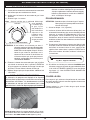
CHECKING AND CONVERTING GAS TYPE
This unit comes from the factory confi gured for one type
of gas, as marked on the label located behind the control
panel, or on the interior of the unit’s enclosure.
Converting this unit to burn a different type of gas
requires a conversion kit (contact your dealer for
details). The professional installer who converts this
unit to burn a different gas must perform the following
functions:
1. Change brass gas orifi ces (included at original shipping)
on each burner to match the new gas type (see
PRODUCT DATA TABLE, Table 1).
2. Switch the convertible gas regulator (if equipped) to
match the new gas type (see section below).
3. Plumb the unit as appropriate for the new gas supply.
4. Apply the label for the new gas (included at original
shipping) over the old gas information found on your
unit.
THIS APPLIANCE REGULATOR IS RATED FOR
1
/
2
PSI MAXIMUM. IF YOUR GAS SUPPLY IS
GREATER THAN
1
/
2
PSI, AN ADDITIONAL REGULATOR MUST BE INSTALLED TO REDUCE
THE INPUT PRESSURE TO THE UNIT to
1
/
2
PSI OR LESS. SEE GAS-SUPPLY REQUIREMENTS
SECTION FOR PROPER GAS-SUPPLY PRESSURE.
CHECKING AND CONVERTING THE REGULATOR
Note: Each end of the plastic converter is engraved with either the letters “NAT”
or “L.P.” (propane) for the respective gasses. When the converter is in the
cap and the cap is held uppermost, the letters seen indicate the gas that
the regulator is set up for.
To convert the regulator from one gas to another, follow steps 1-4.
STEP 2:
Remove the converter (the
plastic stalk) by carefully
pulling it away from the center
of the cap (it will snap out of
its seating).
STEP 1:
Unscrew and remove the cap from the
regulator, extracting the converter.
Regulator: note cap on top
STEP 3:
Turn the converter around and
replace it carefully, into the
center of the cap (it will snap
into place). Check that you can
read the type of gas the unit is
set for.
STEP 4:
Replace the unit into the
regulator and screw down
until snug.
Read gas
type here
WARNING
WARNING
HAZARDOUS OVERHEATING WILL OCCUR IF A
NATURAL-GAS ORIFICE IS USED WITH PROPANE
GAS. IF YOU ARE NOT SURE IF THE CORRECT
ORIFICES ARE INSTALLED, OR IF AN ORIFICE
CHANGE IS NECESSARY, REFER TO THE FOLLOWING
INSTRUCTIONS.
CAUTION: Make sure the unit is at a safe temperature
and isolated from gas and electrical
supplies before beginning the tasks
outlined below.
Note: The cooler the unit, the greater the tolerances
between the stainless-steel parts, and therefore
the easier to disassemble and reassemble
parts of the unit.
CAUTION: For your safety, exercise caution and
use adequate hand protection (such as
gloves) when handling potentially sharp
sheet-metal parts.

16
Important: Test the electrodes for spark before securing
the face to the frame (see also the section
REPLACING THE IGNITOR BATTERY).
9. Replace the face on the frame so the front lip of the face
covers the lip on the frame. Re-secure the face with the
face fastener screws.
10. Replace the control knobs.
11. Replace the fl avor grids and then the cooking grids so that
the cutout section of the grid is in front.
Important The oven and backburner (where fi tted) are
pre-installed at the factory and should not be
removed from the barbecue during installation.
BACKBURNER ORIFICE SIZE CHECKING/
CONVERSION
Before beginning, make sure you have the proper tools for
the task.
This task requires:
• a #2 Phillips-head screwdriver
• a #2 fl at-head screwdriver
• a
3
/
8
" wrench or socket screwdriver
Note: It may be necessary to remove the rotisserie rod
before beginning this procedure.
1. Remove the warming rack, if installed, and set it aside.
2. Remove the backburner cover, if installed.
3. Unscrew both backburner face plate screws using a
Phillips-head screwdriver and set them aside.
4. Remove the backburner face plate by pulling the bottom
toward the front of the barbecue and rotating it upward
and outward until the two top tabs can be removed from
the back wall of the barbecue. Set it aside.
5. Remove the backburner assembly anchoring screw on
the lower left of the backburner using a Phillips-head
screwdriver and set it aside.
CHECKING/CONVERTING THE BURNER ORIFICES
Fig. 16-2 Spark generator
CHECK FUEL ORIFICES FOR PROPER SIZE
1. Your Regal I barbecue is equipped with fuel orifi ces
for natural gas, unless otherwise indicated. To use
with propane gas, you must install smaller orifi ces to
avoid hazardous overheating. Refer to the MODEL
SPECIFICATIONS TABLE for the proper orifi ce size
needed.
2. Remove the cooking grids and fl avor grids from your
barbecue.
3. If the gas supply has been connected, make sure the
burner valves are in the OFF position. Then carefully pull
the valve knobs from their stems.
Note: Carefully, but fi rmly, lift the top panel away from the
frame. The spark generator for the ignition system
is attached to the top panel. The igniter need not
be detached, but the wires must be unplugged
from the generator before the panel is removed.
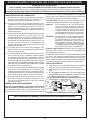
4. Using a fl at blade screwdriver, pry the burner retaining
clip from rear wall of the barbecue frame (see
Fig.16-1).
Remove the burner by; A) Pulling it to the front of the
barbecue; B) Lift the far end out of the notch; C) Pull the
burner away from the manifold, taking care not to lose
the air shutter and spring, which may become detached
when the burner is removed.
5. Using 3/8" socket, remove the orifi ce from the orifi ce
holder on the burner manifold and check the number
stamped on the face. Repeat for each burner as
necessary.
Note: If you have the optional backburner, check the
backburner orifi ce for size.
Note: The air shutter must be re-adjusted after removing
the burner to ensure proper combustion (see the
AIR SHUTTER ADJUSTMENT section).
6. Install the air shutter spring and the air shutter over the
orifi ce holder fi tting in the order and position shown in
Fig. 16-1. Carefully place the burner(s) back in position,
resting on the back fl ange of the inner liner so that the
brass orifi ce and orifi ce holder fi ttings project well into
the burners.
7. Replace all the burner hold down clips.
8. If you removed the top plate re-install the ignition wires.
Your barbecue may have either two (2) or four (4) wires
depending on the exact model. Pull the drip tray out. Lean
the face forward and plug the wires into the terminals on
the spark generator (Fig. 16-2). The wires can be plugged
into any terminal.
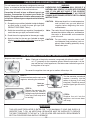
Fig. 16-1 - Burner orifi ce diagram
Burner
Burner neck
Spring
Burner manifold
Orifi ce
Inner liner
Air shutter
Hold down clip
Continued on next page

17
AIR SHUTTER
SCREW
CHECKING/CONVERTING THE BURNER ORIFICES (Cont.)
6. Pull the backburner assembly to the left, clear of the
orifi ce, and then rotate the top forward and downward
and lay it face down across the main burner dividers.
CAUTION: Be careful not to damage the wires
connected to the backburner assembly.
7. Use the socket driver to remove the exposed orifi ce
and replace it with the correct orifi ce for the gas to be
burned (see the MODEL SPECIFICATIONS TABLE
for correct orifi ce sizes, based on burner type and
gas type).
8. Replace the backburner assembly and re-insert the
anchoring screw. Center the backburner assembly
so that the backburner face place will fi t over it.
Tighten the anchoring screw using a Phillips-head
screwdriver.
9. While the backburner faceplate is still off, adjust the
backburner air shutter opening size by loosening
the air shutter adjustment screw with a fl at-head
screwdriver and sliding the air shutter to the position
indicated in the MODEL SPECIFICATIONS TABLE;
then re-tighten the adjustment screw. (see section
on AIR SHUTTER ADJUSTMENT).
10. Replace the backburner face plate by fi rst inserting
the upper tabs into the slots in the back wall of the
barbecue and then rotating the bottom downward
and inward.
11. Replace the two backburner faceplate screws using
a Phillips-head screwdriver.
Tip: Re-attaching the backburner faceplate may be
easier if the left screw is replaced before the right
screw.
THE BACKBURNER COVER
The backburner cover is installed by placing the curved
part of the cover over the top of the perforated portion
of the backburner (see
Fig. 17-2). The cover should be
kept in place on the backburner when it is not in use. This
will keep your backburner free from grease splatter and
debris that may hinder its performance.
Important: You must remove the backburner cover
before lighting the backburner.
Fig. 17-2
Ignitor wire
Orifice
Air
shutter
Electrode
Oven
(right side)
Air shutter
screw
IGNITOR WIRE
ELECTRODE
AIR
SHUTTER
AIR SHUTTER
SCREW
ORIFICE
OVEN
(RIGHT SIDE)
Fig. 17-1

18
MAIN BURNER AIR SHUTTER ADJUSTMENT
Important: The air shutters must be adjusted
after installation. If not, this appliance
may not light, heat evenly, or cook
properly.
Main burner air shutters are easily accessed by
removing the front panel (face). The air shutters are
located at the front of the burners behind the face
(see PARTS LIST). The air shutter has a small dimple
(see Fig.
18-1) that allows it to lock into notches in
the burner face. This prevents the air shutter from
moving.
WARNING
USE PROPERLY INSULATED TOOLS TO MAKE
THESE ADJUSTMENTS. NEVER TOUCH A
HOT BARBECUE DIRECTLY TO MAKE
ADJUSTMENTS.
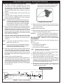
AIR SHUTTER ADJUSTMENT
Partially open
Fig. 18-1
Closed
Fig. 18-2
Fig. 18-1 & Fig. 18-2 - Air shutter adjustment diagram
Flame on ports
Flame off ports
Ta b
(Turn tabs)
Dimple
Notch
1. Using the tip of a long screwdriver, close the air
shutters by turning the tabs to a vertical position
(Fig.
18-2).
2. Light the barbecue in accordance with the
LIGHTING INSTRUCTIONS and burn for two
minutes with the knobs on HI LIGHT and the
oven open.
3. After burning for two minutes, open the air
shutters, using the tip of a screwdriver, until
the fl ames lift off, or appear not to be touching
the burners (Fig.
18-1).
4. Begin closing the air shutters, with the tip of a
screwdriver, until the fl ames appear to burn while
touching the burner ports (Fig.
18-2).
Note: You may then see short yellow tips on the
fl ames. If fl ames are a lazy yellow, open the
air shutters until the fl ame is blue with yellow
tipping.
Note: Barbecues, in some installations, achieve a
better air/gas mixture and will ignite more
quickly if the valve is fi rst turned beyond HI
LIGHT to LOW for lighting.
BACKBURNER AIR SHUTTER ADJUSTMENT
Important: It is normal for the backburner to
smoke when it is burned for the fi rst
time. Burning your backburner on HI
LIGHT for approximately 15 minutes
will eliminate the smoking.
a. The air shutter on your backburner is preset at the
factory. However, due to atmospheric conditions
and different gas pressures, it may be necessary
to adjust the air shutter to obtain a proper burn.
b. First remove the backburner cover (if installed),
then loosen the air shutter screw (see Fig. 18-3).
It may be necessary to use pliers to turn the air
shutter. Light the backburner. With the control
knob on HI LIGHT adjust the air shutter to have
a blue fl ame that is not lifting off the burner (it
may also have slightly yellow tips).
c. Tighten the air shutter adjustment screw.
Fig. 18-3
Air shutter
screw
Main burner air shutters are easily accessed by
removing (when cool) the top panel (face). The air
shutters are controlled by the wire levers at the front
of the burners (see PARTS LIST). The air shutter has
a small dimple (see Fig.
18-1) that allows it to lock
into notches in the burner face. This prevents the air
shutter from moving.
WARNING
ONLY ADJUST 2 AIR SHUTTERS AND THEIR
CORRESPONDING BURNERS AT ONE TIME.
SHUT OFF THE BURNERS PRIOR TO MOVING ON
TO THE NEXT SET.
1. Using the wire levers, close the air shutters
by turning the tabs to a vertical position (Fig.
18-2).
2. Light the corresponding burner pair in accordance
with the LIGHTING INSTRUCTIONS and burn for
two minutes with the knob on HI LIGHT and the
oven open.
3. After burning for two minutes, open the air shutters
using the wire levers until the fl ames lift off, or
appear not to be touching the burners (Fig.
18-
1
).
4. Begin closing the air shutters with the wire levers
until the fl ames appear to burn while touching the
burner ports (Fig.
18-2).
Note: You may then see short yellow tips on the
fl ames. If fl ames are a lazy yellow, open the
air shutters until the fl ame is blue with yellow
tipping.
Note: Barbecues, in some installations, achieve
a better air/gas mixture and will ignite more
quickly if the valve is fi rst turned beyond HI
LIGHT to LOW for lighting.
5. Shut off the burners, then repeat for the next
set.

19
Each time you use the barbecue, make sure that:
1. The area around the barbecue is clear of fl ammable
vapors, liquids, and substances such as gasoline,
yard debris, wood, etc.
2. There is no blockage of the airfl ow through the vent
space located below the face of the unit.
3. When using propane gas:
a. The special ventilation openings in the enclosure
should be kept free and clear of debris
(see PLANNING THE LOCATION OF THE
BARBECUE).
b. If connected to a propane cylinder, the rubber
hose attached to the regulator should be carefully
inspected before each use.
c. The propane cylinder, regulator, and rubber hose should
be installed in a location not subject to heating above
125° F (51° C).
4. The burner fl ames burn evenly along both sides
of each burner with a steady flame, which is
mostly blue. (Refer to section on AIR SHUTTER
ADJUSTMENT.) A proper fl ame pattern will ensure
safe operation and optimal performance. Adjust
the air shutter as needed. If burner fl ames are not
normal, check the orifi ce and burner for insects or
insect nests.
5. The inline gas valve or gas cylinder valve is always
shut OFF when the barbecue is not in use.
6. The drip collector hole is clear and unobstructed.
Excessive grease deposits can result in a grease
fi re.
7. The barbecue is free and clear from combustible
materials, gasoline, and other fl ammable vapors
and liquids.
BARBECUE SAFETY INFORMATION & MAINTENANCE
WARNING
NEVER cover the entire cooking or grill surface with griddles or pans. Overheating will occur and
burners will not perform properly when combustion heat is trapped below the cooking surface.
CAUTION: NEVER spray water on a hot gas unit.
DRIP COLLECTION SYSTEM
The drip collector in this barbecue is part of the unit’s
main frame and is located below the burners. The drip
collector has slots that will allow excess drippings to
fall through during cooking, while separating the fi rebox
from the drip tray. Clean the drip tray after each use.
The drip collector allows you to brush or scrape residue
from the barbecue’s inner liner into the drip tray.
Following the manufacturers instructions and regular
cleaning of the barbecue’s interior with oven cleaner,
will help to prevent grease fi res.
Periodically check the burners to make sure they are
clear of debris. Properly adjusted burner fl ames burn
evenly along both sides of each burner with a steady
fl ame (mostly blue). If burner fl ames are not normal,
check the orifi ce and burner for insects or insect nests.
(See section on CHECKING/CONVERTING THE
BURNER ORIFICES for instructions on burner removal
and replacement.)
Check the burner ports at least annually for blockage by
removing the burner (see orifi ce changing instructions)
and visually inspect the gas intake tube for insects
and nests. A clogged tube can lead to a fi re beneath
the grill.

20
ÉCLAIRAGE ÉLECTRONIQUE
1. Ouvrez tous les couvercles et enlevez toutes les couvertures
des brûleurs que vous souhaitez vous allumer.
2. Arrêtez tous les boutons de commande de gaz à leurs
positions.
3. Allumez le gaz à sa source.
Note: Aucune matière que la méthode d’éclairage
vous emploient,
n’allument pas
le gaz à plus
d’un brûleur à la
fois. Les brûleurs
adjacents de
barbecue croix-
mettront à feu
et l’écoulement
de gaz peut être
restreint.
ATTENTION: Si les brûleurs ne s’allument pas dans 5
secondes, enfoncez le bouton de commande
et tournez le bouton à AU LOIN. ATTENDEZ 5
MINUTES avant de répéter l’étape 5. Si vous
sentez le gaz suivez les instructions sur la
couverture de ce manuel. Si les brûleurs ne
s’allument toujours pas après que plusieurs
tentatives, se rapportent aux instructions pour
l’ÉCLAIRAGE MANUEL.
4. Enfoncez le bouton de commande pour que le brûleur
soit allumé et tournez-le dans la position LÉGÈRE de
HI, puis appuyez sur le bouton d’allumage. Une fois que
le brûleur s’allume, libérez le bouton d’allumage.
5. Répétez l’étape 4 pour que chaque brûleur additionnel soit
s’est allumé.
POUR LE PROPANE SEULEMENT
Les réservoirs de propane sont équipés d’un dispositif
d’arrêt de sûreté qui peut ne pas causer le bas ou aucun gaz
pressure/fl ame aux brûleurs si le fonctionnement et allumer
des instructions ne sont pas suivis exactement (voir la note
importante dans la section de dépannage pour plus de détails.)
Note: Les barbecues dans quelques installations
réalisent un meilleur mélange d’air/gas et mettront
à feu plus rapidement si le bouton de commande de
brûleur est d’abord tourné au delà de la LUMIÈRE
de HI au BAS pour l’éclairage.
ÉCLAIRAGE MANUEL
ATTENTION: Attendez toujours 5 minutes le gaz à l’espace
libre après que n’importe quelle tentative non
réussie d’éclairage.
1. Suivez les étapes 1 à 4 (à gauche).
2. Insérez un allumeur brûlant de butane de long-baril, une
allumette brûlante de long-tige, ou une allumette brûlante
tenue par un support de prolongation de fi l (Fig. 20-2)
par les grilles à cuire au brûleur (Fig. 20-3). Pour des
backburners, tenez la fl amme contre le matériel perforé
du brûleur arrière. Pour des sideburners, tenez la fl amme
contre le brûleur.
3. Tout en tenant l’allumette ou la fl amme plus légère à côté
du brûleur, enfoncez le bouton de commande approprié
de brûleur et tournez-le dans le sens contraire des
aiguilles d’une montre dans la position LÉGÈRE de HI.
Quand les lumières de brûleur, enlèvent l’allumeur ou
s’assortissent.
4. Si le brûleur ne s’allume pas, enfoncez immédiatement
le bouton et tournez le bouton de commande de brûleur
à AU LOIN. ATTENDEZ 5 MINUTES avant de répéter
les étapes 2 à 4 des INSTRUCTIONS MANUELLES
d’ÉCLAIRAGE.
COUPER LE GRIL
Pour couper le gril, enfoncez chaque bouton de commande
de valve et tournez-le dans le sens des aiguilles d’une montre
à la position de repos.
Fermez toujours la valve à l’offre de gaz après chaque
utilisation du barbecue.
RAPPELEZ-VOUS: POUR L’ÉCLAIRAGE MANUEL SÛR, PLACEZ
Un ALLUMEUR BRÛLANT D’ALLUMETTE OU De BUTANE PRÈS
Du BRÛLEUR - ALLUMEZ ALORS Le GAZ
(voyez Fig. 20-3).
Fig. 20-2 - Support d’allumette
Lisez l’instruction entière avant que s’allumant et suivez ces instructions chaque fois vous lumière le barbecue.
ALLUMER DES INSTRUCTIONS (D’ALLUMAGE)
Fig. 20-3 - Éclairage manuel
Fig. 20-1 - Valve control knob
OFF
HI
LIGHT
LOW
TO
TURN OFF
TO TURN ON
Read setting
here
HIGH to
LIGHT
Read setting
here
TO TURN OFF
TO TURN ON
High to
light
La page est en cours de chargement...
La page est en cours de chargement...
La page est en cours de chargement...
La page est en cours de chargement...
La page est en cours de chargement...
La page est en cours de chargement...
-
 1
1
-
 2
2
-
 3
3
-
 4
4
-
 5
5
-
 6
6
-
 7
7
-
 8
8
-
 9
9
-
 10
10
-
 11
11
-
 12
12
-
 13
13
-
 14
14
-
 15
15
-
 16
16
-
 17
17
-
 18
18
-
 19
19
-
 20
20
-
 21
21
-
 22
22
-
 23
23
-
 24
24
-
 25
25
-
 26
26


dans d''autres langues
- English: FireMagic 34S2S0P0 User manual
Documents connexes
Autres documents
-
Fire Magic REGAL 1 Le manuel du propriétaire
-
 American Outdoor 30NB-00SP Le manuel du propriétaire
-
-
-
 ProFire PF48RS Le manuel du propriétaire
-
 American Outdoor 24NG-00SP Le manuel du propriétaire
-
-
American Outdoor 24PC-00SP Le manuel du propriétaire
-
 American Outdoor Grill 30 series Mode d'emploi
-
Fire Magic E1060i Le manuel du propriétaire


