
www.debem.it
EQUAFLUX 03/2014
INDUSTRIAL PUMPS - INDUSTRIENPUMPEN
petrochemical, food, mechanical, environmental, printing, chemical, painting, galvanic, textile and ceramic, industry
GB
INSTRUCTIONS FOR USE AND MAINTENANCE
D
HINWEISE ZUR VERWENDUNG UND WARTUNG
EQUAFLUX
E
ISTRUZIONI PER L’USO
E LA MANUTENZIONE
I
EQUAFLUX
F
GB
D
COD. EQUA ATEX/GD 3-03-2006
EQUAFLUX 51
EQUAFLUX 100
EQUAFLUX 200
EQUAFLUX 300
INSTRUCTIONS FOR USE
AND MAINTENANCE
MODE
D’EMPLOI
BEDIENUNGS-UND
WARTUNGSANLEITUNGEN
MANUAL DE USO Y
MANTENIMIENTO
Dossier according
to 94/9/EG 8. b II stored
TÜV NORD Italia
S.r.l.
I
S
O
9
0
0
1

2
debem.it
Debem SRL
2014
Alle Rechte der vollständigen oder teilweisen Übersetzung,
des Nachdrucks und der Anpassung auf irgendeine Weise
sind in allen Ländern vorbehalten.
Debem SRL
2014
All rights of total or partial translation, reproduction
and adaptation by any means are reserved
in all countries.

3
debem.it
INHALT
SEITE
VORWORT 4
EINFÜHRUNG IN DAS HANDBUCH 4
IDENTIFIKATION DES DÄMPFERS 5
KENNZEICHNUNGEN UND ALLGEMEINE INFORMATIONEN 6
IDENTIFIKATIONSCODE 7
BESCHREIBUNG DES DÄMPFERS 8
TECHNISCHE CHARAKTERISTIKA 10
GARANTIE 12
SICHERHEITSANFORDERUNGEN 13
TRANSPORT UND POSITIONIERUNG 16
ANSCHLUSS DES PRODUKTKREISLAUFS 18
PNEUMATISCHER ANSCHLUSS 20
INBETRIEBNAHME 22
WARTUNG DES PRODUKTKREISLAUFS 24
A- REINIGUNG UND ERSATZ DER MEMBRANEN 26
WARTUNG DES LUFTKREISLAUFS 28
A-ERSATZ DER PNEUMATISCHEN VENTILE 29
FEHLERBEHEBUNG 30
STILLLEGUNG 31
ENTSORGUNG UND RÜCKBAU 31
ERSATZTEILE 32
INDEX
PAGE
FOREWORD 4
INTRODUCTION 4
DAMPENER IDENTIFICATION 5
MARKINGS AND GENERAL INFORMATION 6
IDENTIFICATION CODES 7
DAMPENER DESCRIPTION 8
TECHNICAL FEATURES 10
WARRANTY 12
SAFETY RULES 13
TRANSPORT AND POSITIONING 16
CONNECTING THE PRODUCT CIRCUIT 18
PNEUMATIC CONNECTION 20
COMMISSIONING 22
PRODUCT CIRCUIT MAINTENANCE 24
A- CLEANING AND REPLACING THE DIAPHRAGMS 26
AIR CIRCUIT MAINTENANCE 28
A- REPLACING THE AIR VALVE 29
TROUBLESHOOTING 30
DECOMMISSIONING 31
DEMOLITION AND DISPOSAL 31
SPARE PARTS 32
GB
D

4
debem.it
VORWORT
Die Pulsationsdämpfer EQUAFLUX wurden in Übereinstim-
mung mit den Richtlinien 2006/42/EG, 94/9/EWG und 99/92/
EG hergestellt. Die entsprechenden Kriterien der Gebiete
werden in den harmonisierten europäischen Normen EN-
60079-10 und EN 1127-1 angegeben. Daher stellen sie keine
Gefahren für den Bediener, wenn sie nach den Anweisungen
dieses Handbuchs verwendet werden. Das Handbuch muss
für zukünftiges Nachschlagen des Wartungspersonals in gu-
tem Zustand und/oder in der Nähe der Maschine aufbewahrt
werden. Der Hersteller lehnt jede Haftung für Änderungen,
Manipulationen, falsche Anwendungen oder Arbeiten, die den
Inhalt dieses Handbuchs nicht einhalten und die Schäden an
der Gesundheit und Sicherheit von Personen, Tieren und Ge-
genständen in der Nähe des Dämpfers verursachen können,
ab. Der Hersteller hofft, dass es Ihnen möglich sein wird, die
vollen Leistungen der Dämpfer EQUAFLUX zu nutzen. Alle
technischen Angaben beziehen sich auf die Standarddämpfer
EQUAFLUX (siehe “TECHNISCHE CHARAKTERISTIKA“),
aber es wird darauf hingewiesen, dass aufgrund der ständi-
gen Suche nach technologischen Innovationen und Qualität
die angegebenen Charakteristika ohne Vorankündigung ge-
ändert werden können. Alle Zeichnungen und Darstellungen
in den mit dem Gerät gelieferten Dokumenten sind Eigentum
des Herstellers, der sich alle Rechte vorbehält und die Weiter-
gabe an Dritte ohne seine vorherige schriftliche Genehmigung
VERBIETET.
ES SIND DAHER ALLE REPRODUKTIONEN, AUCH TEIL-
WEISE, DES HANDBUCHS, DES TEXTES UND DER
ZEICHNUNGEN STRENGSTENS VERBOTEN.
FOREWORD
EQUAFLUX pulsation dampeners have been manufactured
tothe 2006/42/CE, 94/9/CEE and 99/92/EC directives.
The relevant area criteria are indicated in the EN-60079-10 and
EN 1127-1harmonized European standards.
Therefore, if used according to the instructions contained in
thismanual, the dampener will not represent any risk to the
operator. This manual must be preserved in good condition
and/oraccompany the machine as reference for maintenance
pur-poses. The manufacturer rejects any liability for any
alteration,modication, incorrect application or operation not
complyingwith the contents of this manual and that may cause
damagethe health and safety of persons, animals or objects
stationingnear the dampener.The Manufacturer trusts you will
be able to make full use of theperformances offered by the
EQUAFLUX dampeners.All the technical values refer to the
standard version of theEQUAFLUX dampeners (please see
“TECHNICAL FEATURES”). However, our continuous search
for innovation and improve-ments in the technological quality
mean that some of the featuresmay change without notice.
All drawings and any other represen-tation in the documents
supplied with the device are property ofthe Manufacturer who
reserves all rights and FORBIDS distribution to third parties
without his authorization in writing.
THEREFORE REPRODUCTION, EVEN PARTIAL, OF
THISMANUAL, TEXT OR DRAWINGS ARE STRICTLY
FORBIDDEN.
GB
EINFÜHRUNG IN DAS HANDBUCH
Das vorliegende Handbuch ist integraler Bestandteil des
Pulsationsdämpfers und stellt eine SICHERHEITSEINRICH-
TUNG. Es enthält wichtige Informationen, die dem Käufer und
seinen Mitarbeitern helfen, den Dämpfer bei der Installation,
Verwendung und Wartung seiner gesamten Lebensdauer in
guten Zustand zu bewahren.
Zu Beginn jedes Kapitels und jedes Abschnitts wurde ein In-
formationsfeld eingefügt, das dem für die Eingriffe geschultem
Personal durch Symbole die obligatorische persönliche Schutz-
ausrüstung und/oder den Energiestatus des Dämpfers anzeigt.
Jedes Restrisiko, das während des Vorgangs auftreten kann,
wird durch entsprechende Symbole, die im Text integriert sind,
angezeigt. Spezielle Symbole werden auch verwendet, um
besondere Informationen oder Ratschläge bezüglich der Si-
cherheit und der ordnungsgemäßen Verwendung des Dämpfers
hervorzuheben und zu differenzieren.
FÜR ALLE WEITEREN INFORMATIONEN BEZÜGLICH DES
INHALTS DIESES HANDBUCHS KONTAKTIEREN SIE BITTE
DEN KUNDENSERVICE DES HERSTELLERS.
ACHTUNG: dieses Zeichen zeigt dem verant-
wortlichen Personal an, dass der beschriebene
Vorgang ein Expositionsrisiko mit Restgefahren
mit der Möglichkeit von gesundheitlichen Schäden oder
Verletzungen birgt, wenn die beschriebenen Verfahren
und Anforderungen nicht in Übereinstimmung gemäß den
Sicherheitsvorschriften ausgeführt werden.
INTRODUCTION
This manual is an integral part of the pulsation dampener,
andrepresents a SAFETY DEVICE. It contains important
informa-tion that will assist the purchaser and his personnel in
installing, using and servicing the dampener in good condition
and safety during service life.
At the head of every chapter an information eld with symbol
sindicates the personnel who are authorized to perform the
operation described in that page along with the individual
protec-tive devices that must be worn and/or the energetic
state of thedampener.
Any residual risk that may occur during these operations
ishighlighted by special symbols embedded in the text.Special
symbols are also used to highlight and differentiate anyparticular
information or suggestion concerning safety and cor-rect use.
PLEASE CONTACT THE MANUFACTURER’S
CUSTOMER ASSISTANCE DEPARTMENT FOR
ANY FURTHER INFORMATION REGARDING THE
CONTENTS OF THIS MANUAL.
WARNING: this sign warns the personnel involved that
failure to perform the operation described in compliance
with the procedures and prescriptions related to safety
regulations entails residual risks that may cause damage
to health or injuries.
GB
!
!
D
D

5
debem.it
HINWEIS: dieses Zeichen zeigt dem verantwortlichen
Personal, das der beschriebene Vorgang Schäden an
der Maschine und/oder ihren Komponenten und folglich
Risiken für den Bediener und/oder die Umwelt verursachen kann,
wenn er nicht in Übereinstimmung gemäß den Sicherheitsvor-
schriften ausgeführt wird.
ANMERKUNG: dieses Zeichen liefert Informationen
über den laufenden Betrieb, deren Inhalt von relevanter
Bedeutung ist.
SYMBOLE DER OBLIGATORISCHEN UND PERSÖNLI-
CHEN SCHUTZAUSRÜSTUNG: dieses Zeichen zeigt die
Picht zum Tragen angemessener persönlicher Schutzaus-
rüstung und den Energiestatus aufgrund der Gefahren, die
beim Betrieb auftreten können, an.
BEDIENER: diese Qualikation setzt umfassende Kennt-
nisse und volles Verständnis der in der Bedienungsan-
leitung des Herstellers enthaltenen Informationen sowie
spezische Fähigkeiten in Bezug auf den Anwendungsbereich
voraus.
INSTALLATIONS- UND WARTUNGSPERSONAL:
diese Qualikation setzt umfassende Kenntnisse und
volles Verständnis der in der Bedienungsanleitung des
Herstellers enthaltenen Informationen, spezisches Fachwissen
bei der Installation und gewöhnlichen Wartung sowie spezische
Fähigkeiten in Bezug auf den Anwendungsbereich voraus.
ACHTUNG: das für die Installation, Inspektion und
Wartung der Pumpe verantwortliche Personal muss
über eine angemessene technische Ausbildung mit
ausreichenden Kenntnissen über explosionsgefährdete Be-
reiche und die damit verbundenen Risiken verfügen.
AUSSERORDENTLICHE VERFAHREN: identiziert
die Eingriffe, die den Technikern des Kundenservices
vorbehalten sind und ausschließlich in der Werkstatt des
Herstellers durchgeführt werden.
CAUTION: This sign informs involved personnel that
failure to perform the described operation in compli-
ance with safety regulations may cause damage to
the machine
and/or its components hence risks for the operator and/or the
environment.
REMARK: This sign provides information regarding the
current operation and its contents are very important.
COMPULSORY AND INDIVIDUAL PROTECTION
SIGNS: These signs indicate that proper individual pro-
tection must also be used against energetic events be-
cause of the dangers that may arise during the operation.
OPERATOR: this function entails full knowledge and
understanding of the information contained in the user
manual issued by the Manufacturer as well as specic
skills related to the sector of use.
GB
INSTALLER AND MECHANICAL SERVICEMAN:
This function entails full knowledge and understanding
of information contained in the user manual issued
by the manufacturer, specic expertise in installation and
ordinary maintenance tasks as well as specic skills related
to the sector of use.
WARNING The personnel in charge of installing,
testing and servicing the pump must have a suitable
technical knowledge of potentially explosive
atmospheres and of the relevant risks.
EXTRAORDINARY PROCEDURES: Identies opera-
tions that can only be performed by the after-sales
service technicians at the Manufacturer’s premises.
!
!
IDENTIFIKATION DES DÄMPFERS
Jeder Pulsationsdämpfer ist mit einem Typenschild ausgestattet,
das die Spezikationen und das Baumaterial angibt. Bei jeglicher
Kommunikation mit dem Hersteller, dem Händler oder den auto-
risierten Kundenzentren sind diese Daten anzugeben.
ACHTUNG: es ist verboten, das Typenschild der Pum-
pe und/oder die auf dem Typenschild angegebenen
Daten zu entfernen und/oder zu verändern.
Der Identikationscode *, der unter dem Punkt “TYP” des Typen-
schilds erscheint, speziziert die Zusammensetzung und das
Baumaterial der Pumpe, um die Eignung mit dem Produkt, das
gepumpt werden soll, zu bestimmen.
DAMPNER IDENTIFICATION
Each dampener has an identication plate carrying its speci-
cation details and materials. Always refer to this data when
contacting the manufacturer, dealer or customer service centers.
WARNING: removing or altering this identication
plate and or the data it contains is forbidden.
Identication code * on the plate against the “TYPE” heading
species the composition and the materials used to build the
pump. This data will help ascertain whether the pump is suitable
for the product to be pumped.
GB
!
!
1
I
EQUAFLUX - INTEGRAZIONE
(p. 25 ) Gli operatori preposti alle operazioni di montaggio/smontaggio devono essere formati circa i pericoli connessi all’utilizzo di utensili
meccanici, anche di piccole dimensioni.
(p.30) Posizionare i seguenti segnali di divieto e pericolo in prossimità del luogo di installazione della pompa
(p.25) The operators in charge of the assembly / disassembly must be informed and trained on the dangers relating to the use of
mechanical tools, even small ones .
(p.30) Put the following prohibition and danger signs near the place where the pump is installed
(p.18 E-F) Prima di intervenire sulla pompa e/o prima di eseguire interventi di manuten-
zione o riparazione bisogna:
• attendere il raffreddamento della pompa per almeno quindici minuti;
• eseguire le operazioni necessarie indossando guanti di protezione e tutti gli altri oppor-
tuni dispositivi di protezione individuali (maschere facciali, guanti, scarpe chiuse, etc.):
pericolo di eiezione di uido in pressione e scottature.
(p29) vericare che le tubazioni di allacciamento alla pompa siano pulite al loro interno e
che non contengano assolutamente residui di lavorazione
(p.5) Dichiarazione CE di conformità.
(p.18 E-F) Before intervening on the pump and/or before carrying out maintenance or
repair operations, you must
• Wait for the pump to cool down for at least fteen minutes
• Perform the necessary operations while wearing protection gloves and any other
appropriate personal protection equipment (face masks, gloves, closed shoes, etc.):
Danger of burning and ejection of liquid under pressure.
(p.29) Check if the connection tubes to the pump are clean inside and do no contain any
working residue.
(p.5) EC conformity declaration.
segnale
di pericolo
generico
General
Danger Sign
pericolo
materiale
corrosivo
Danger
Corrosive
Material
pericolo
materiale
inammabile
Danger
Flammable
Material
pericolo
materiale
esplosivo
Danger
Explosive
Material
pericolo
materiale
tossico
Danger Toxic
Material
pericolo di spruzzi
di materiale liquido
incandescente
Danger
Incandescent
Liquid Sprinkles
divieto di
usare amme
libere
Prohibition
on Open
Flames’ Use
divieto di
fumare
No smoking
EQUAFLUX - INTEGRATION
GB
EQUAFLUX STANDARD
DICHIARAZIONE DI CONFORMITA’
DECLARATION DE CONFORMITE - DECLARACION DE CONFORMIDAD
ERKLÄRUNG BEZÜGLICH EINHALTUNG DER VORSCHRIFTEN - DECLARATION OF CONFORMITY
TIPO/SERIE
TYPE / SERIE- TIPO / SERIE - TYP / SERIE - TYPE / SERIES
FABBRICATO DA:
FABRIQUE PAR - FABRICADA POR - HERGESTELLT VON - MANUFACTURED BY
MARCATURA ATEX
MARKING ATEX - MARQUAGE ATEX - MARKIERUNG ATEX - MARCAR ATEX
MODELLO
MODELE - MODELO - MODELL - MODEL
CODICE
CODE - CODE - KODE - CODICE
MATRICOLA
SERIAL NUMBER - MATRICULE - MATRIKELNUMMER - MATRICULA
DEBEM SRL - Via del bosco 41 - 21052 Busto Arsizio (VA) - ITALIA
II 3/3 GD c IIB T135ºC
Questo prodotto è conforme alle seguenti direttive CE/EX e relativi standard armonizzati:
This product complies with the following European Community Directives CE/EX and relating harmonized standards:
Ce produit est conforme aux directives de la Communautè europèenne suivantes CE/EX et les normes correspondantes harmonisées:
Este producto cumple con las siguientes Directrices de la Comunidad Europea CE/EX y relativas normas armonizadas:
Dieses Produkt erfüllt die folgenden Vorschriften der Europäischen Gemeinschaft CE/EXund entsprechende harmonisierte Normen:
2006/42/CE Direttiva Macchine / Machinery Directive / Maschinenrichtlinie / Directive Machines / Directiva Máquinas
94/9/CE: Direttiva ATEX, concernente il ravvicinamento delle legislazioni degli Stati Membri relative agli apparecchi e sistemi di protezione destinati a essere utilizzati in
atmosfera potenzialmente esplosiva.
94/9/EC: ATEX Directive, on the approximation of European Member States laws concerning protection equipments and systems to be used in potentially explosive envi-
ronments.
94/9/CE : Directive ATEX, concernant le rapprochement des législations des états-membres relatives aux appareils et aux dispositifs de protection utilisés en environne-
ment potentiellement explosif.
94/9 CE: ATEX Richtlinie über die Angleichung der Rechtsvorschriften der Mitgliedstaaten für Geräte und Schutzsysteme zur bestimmungsgemäßen Verwendung in ex-
plosionsgefährdeten Bereichen.
94/9/CE: Directiva ATEX, relativa el acercamiento de las legislaciones de los Estados Miembros relativas a los aparatos y sistemas de protección destinados a ser uti-
lizados en atmósfera potencialmente explosiva.
CE MACCHINE 98/37/CE
EN 13463 – 1 EN 13463 - 5 EN 1127-1
LA SEGUENTE CONFORMITA’ E’ RIFERITA AL PROTOTIPO DELLA EQUAFLUX 100 PP MATRICOLA NR. E00001 - 02.05.2003.
THIS COMPLIANCE REFERS TO QUAFLUX 100 PP, PROTOTYPE SERIAL NUMBER E00001 - 02.05.2003.
LA NORME SUIVANTE SE RAPPORTE AU PROTOTYPE DE LA BQUAFLUX 100 PP MATRICULE N° E00001 - 02.05.2003.
DIE VORLIEGENDE KONFORMITÄTSERKLÄRUNG BEZIEHT SICH AUF DEN PROTOTYP DER QUAFLUX 100 PP, MATRIKEL-NR. E00001 - 02.05.2003.
LA SIGUIENTE CONFORMIDAD SE REFIERE AL PROTOTIPO DE QUAFLUX 100 PP, MATRÍCULA N. E00001 - 02.05.2003.
ESTENSIONI: la presente dichiarazione si estende anche ai modelli EQUAFLUX 51, EQUAFLUX 200, EQUAFLUX 302, EQUAFLUX 303.
EXTENSION: this declarations is also valid for the following versions EQUAFLUX 51, EQUAFLUX 200, EQUAFLUX 302, EQUAFLUX 303.
EXTENSION:cette declaration est également valable pour les modèles suivantes EQUAFLUX 51, EQUAFLUX 200, EQUAFLUX 302, EQUAFLUX 303.
inserire qui tipo/serie
inserire qui modello
inserire qui codice
inserire qui matricola
STANDARD
I
GB
F
D
E
IDENTIFICAZIONE
SMORZATORE
Ogni smorzatore di pulsazioni è corredato
di una matricola di identificazione che
riporta le specifiche e i materiali di compo-
sizione. Per qualsiasi comunicazione con
il costruttore, il rivenditore o i centri di
assistenza autorizzati precisare i dati
riportati.
ATTENZIONE: è vietato rimuovere e/o
alterare la matricola di identificazio-
ne dello smorzatore di pulsazioni e/o i
dati in essa riportati.
Il codice identificativo * che compare alla
voce “TIPO” della matricola specifica la
composizione ed i materiali costruttivi
della pompa al fine di determinare
l’idoneità con il prodotto che si desidera
pompare.
5
!
DAMPENER IDENTIFICATION
Each dampener has an identification plate
carrying its specification details and
materials.
Always refer to this data when contacting
the manufacturer, dealer or customer ser-
vice centers.
WARNING: removing or altering this
identification plate and/or the data it
contains is forbidden.
!
Identification code * on the plate against
the “TYPE” heading specifies the compo-
sition and the materials used to build the
pump. This data will help ascertain
whether the pump is suitable for the prod-
uct to be pumped.
IDENTIFICATION AMORTISSEUR
Toutes les amortisseurs présentent une
plaque d’identification contenant les spéci-
fications et les matériaux qui la composent.
Toute communication avec le constructeur,
le revendeur ou les services après-vente
agréés doit contenir les données de
plaque.
ATTENTION: Il est interdit de retirer
et/ou d’altérer la plaque
d’identification de l’amortisseur de pulsa-
tions et/ou les données qu’elle contient.
Le code d’identification * affiché à la rubri-
que “TYPE” de la plaque indique la com-
position et les matériaux de construction
de la pompe pour déterminer son adapta-
tion au produit à pomper.
!
IDENTIFIKATION DÄMPFER
Jeder Pulsschlagdämpfer ist mit einem
Matrikelschild zur Identifikation versehen,
welches technische Angaben und die
verwendeten Materialien enthält. Bei
jedem Kontakt mit dem Hersteller, dem
Verkäufer oder dem zuständigen Kunden-
dienst die angegebenen Daten mitteilen.
ACHTUNG: Es ist absolut verboten,
das Matrikelschild zur Identifikation
des Pulsschlagdämpfers zu entfernen
und/oder die darin enthaltenen Daten
abzuändern.
Der Identifikationsschlüssel, der unter
„TYP“ des Matrikelschildes erscheint, gibt
die Zusammensetzung und die
Konstruktionsmaterialien der Pumpe an,
um die Eignung für das Produkt, das
gepumpt werden soll, zu bestimmen.
!
IDENTIFICACION
AMORTIGUADOR
Cada amortiguador de impulsos consta
de una matrícula de identificación con las
especificaciones y los materiales de los
elementos que la componen. Ante
cualquier comunicación con el fabricante,
el revendedor o los centros de asistencia
autorizados es necesario suministrar los
datos indicados en dicha matrícula.
ATENCION: está prohibido sacar y/o
alterar la matrícula de identifica-
ción del amortiguador de impulsos y/o
los datos contenidos en la misma.
El código de identificación * que aparece
en el renglón “TIPO” de la matrícula
especifica la composición y los
materiales de fabricación de la bomba
con la finalidad de determinar si la
misma es adecuada para el producto que
se desea bombear.
!
STANDARD
CONDUCT
CONDUCT
II 2/2 GD c IIB T135°C
II 3/3 GD c IIB T135°C
D
D

6
debem.it
KENNZEICHNUNG UND ALLGEMEINE INFORMATIONEN
MARKINGS AND GENERAL INFORMATION
In compliance with the 94/9/CEE standards, the EQUAFLUX
pulsation dampeners carry the following identication marks:
II 2/2 GD c IIB T135°C
: safety symbol to Din 40012 attachment A.
II 2/2GD: surface equipment for use in areas with the presence
of gases, vapors or mists in addition to clouds of combustible
dust in the air that occur occasionally during normal opera-
tion (EN 1127-1 par. 6.3), both in external and internal areas
(ZONE 1).
c: protection by constructional safety (EN 13463-5).
IIB: Excluding the following products hydrogen, acetylene,
carbon disulphide.
T135°C: Class of admitted temperatures. The processed uid
temperature value must fall within such class range and the
user must comply with the instructions contained in the manual
and with the current laws. Furthermore, the user must take
into account the ignition point of the gases, vapors and mists
in addition to clouds of combustible powder in the air existing
in the area of use.
The technical sheet is deposited with TÜV NORD CERT
Hanover.
Die Dämpfer EQUAFLUX in Übereinstimmung mit der Richtlinie
94/9/EWG tragen die folgende Kennzeichnung:
II 2/2 GD c IIB T135°C
: Sicherheitssymbol in Übereinstimmung mit DIN 40012
Anhang A.
II 2/2 GD: Oberirdische Anlage für die Verwendung in Bereichen
mit Vorhandensein von Gas, Dämpfen oder Nebel sowie Wol-
ken aus brennbarem Staub in der Luft, die gelegentlich beim
Normalbetrieb, sowohl im Außen- als auch im Innenbereich,
auftreten (ZONE 1).
c: Geräteschutz durch konstruktive Sicherheit (EN 13463-5).
IIB: mit Ausnahme der folgenden Produkte: Wasserstoff, Ace-
tylen, Schwefelkohlenstoff.
T135°C: Klasse der zugelassenen Temperaturen. Der An-
wender muss Fluide bei einer Temperatur innerhalb dieser
Klassikation verarbeiten. Dabei sind die in diesem Handbuch
wiedergegebenen Anweisungen und die gesetzlich geltenden
Bestimmungen zu berücksichtigen. Weiterhin muss der An-
wender die Zündtemperaturen der Gase, Dämpfe oder Nebel
sowie der brennbaren in der Luft des Anwendungsbereichs
vorhandenen Stäube berücksichtigen.
Das technische Datenblatt ist beim TÜV NORD CERT in
Hannover hinterlegt.
GB
In compliance with the 94/9/CEE standards, the EQUAFLUX
pulsation dampeners carry the following identication marks:
II 3/3 GD c IIB T135°C
: safety symbol to Din 40012 attachment A.
II 3/3GD: surface equipment used in areas where the presence
of gas, vapors or mists in addition to clouds of combustible
powder in the air is unlikely during normal operation both in
external and internal areas and, if it does occur, it will only
persist for a short period (ZONE 2).
c: protection by constructional safety (EN 13463-5).
IIB: Excluding the following products: hydrogen, acetylene,
carbon disulphide.
T135°C: Class of admitted temperatures. The processed uid
temperature value must fall within such class range and the
user must comply with the instructions contained in the manual
and with the current laws. Furthermore, the user must take
into account the ignition point of the gases, vapors and mists
in addition to clouds of combustible powder in the air existing
in the area of use.
The technical sheet is deposited with TÜV NORD CERT
Hanover.
Die Dämpfer EQUAFLUX in Übereinstimmung mit der Richtlinie
94/9/CEE tragen die folgende Kennzeichnung:
II 3/3 GD c IIB T135°C
: Sicherheitssymbol in Übereinstimmung mit DIN 40012
Anhang A.
II 3/3GD: Oberirdische Anlage für die Verwendung in Bereichen in
denen das Vorhandensein von Gas, Dämpfen oder Nebel sowie
Wolken aus brennbarem Staub in der Luft beim Normalbetrieb,
sowohl im Außen- als auch im Innenbereich, unwahrscheinlich
oder für kurze Zeiträume selten ist (ZONE 2).
c: Geräteschutz durch konstruktive Sicherheit (EN 13463-5).
IIB: mit Ausnahme der folgenden Produkte: Wasserstoff, Acetylen,
Schwefelkohlenstoff.
T135°C: Klasse der zugelassenen Temperaturen. Der Anwender
muss Fluide bei einer Temperatur innerhalb dieser Klassikation
verarbeiten. Dabei sind die in diesem Handbuch wiedergegebenen
Anweisungen und die gesetzlich geltenden Bestimmungen zu be-
rücksichtigen. Weiterhin muss der Anwender die Zündtemperatu-
ren der Gase, Dämpfe oder Nebel sowie der brennbaren in der Luft
des Anwendungsbereichs vorhandenen Stäube berücksichtigen.
Das technische Datenblatt ist beim TÜV NORD CERT in
Hannover hinterlegt.
D

7
debem.it
IDENTIFIKATIONSCODE
IDENTIFICATION CODE
GB
D
EQ51-
EQ51 - Equaux 51
EQ100 - Equaux100
EQ200 - Equaux200
EQ302 - Equaux302
EQ303 - Equaux303
FQ 51 - Foodequaux 51
FQ 100 - Foodequaux 100
FQ 200 - Foodequaux200
FQ 302 - Foodequaux 302
P - polypropylene
FC - PVDF+CF
R - PPS-V
A - Aisi 316 (except EQ 303)
AL - Alu
PC - PP + CF
H = Hytrel
M = Santoprene
H = Hytrel
T = PTFE
(zona 1)
C = if required
(zona 1)
C = if required
P-
H T C
II 2/2 GD c IIB T135°C
II 2/2 GD c IIB T135°C
A - Aisi 316
T = PTFE
DAMPNER BODY
DUMPNER MODEL
DAPHRAGMS
AIR SIDE
DIAPHRAGMS
FLUID SIDE
CONDUCT
VERSION
EQ51-
EQ51 - Equaux 51
EQ100 - Equaux100
EQ200 - Equaux200
EQ302 - Equaux302
EQ303 - Equaux303
FQ 51 - Foodequaux 51
FQ 100 - Foodequaux 100
FQ 200 - Foodequaux 200
FQ 302 - Foodequaux 302
P - Polypropylen
FC - PVDF+CF
R - PPS-V
A - Aisi 316 (außer EQ 303)
AL - Aluminium
PC - PP + CF
H = Hytrel
M = Santoprene
H = Hytrel
T = PTFE
(zone 1)
C = bei Bedarf
(zone 1)
C = bei Bedarf
P-
H T C
II 2/2 GD c IIB T135°C
II 2/2 GD c IIB T135°C
A - Aisi 316
T = PTFE
DÄMPFERKÖRPER
DÄMPFER
MEMBRAN
LUFTSEITE
MEMBRAN
FLUIDSEITE
CONDUCT
AUSFÜHRUNG

8
debem.it
BESCHREIBUNG DES DÄMPFERS
Verwendungszweck
Die Dämpfer EQUAFLUX wurden entworfen und gebaut, um
automatisch die Schwankungen von Förderhöhe und Leistung
hinter der pneumatischen Membranpumpe für Flüssigkeiten
aus chemisch, mit den Baukomponenten kompatiblen Materi-
al, zu dämpfen. Der Betrieb des Dämpfers ist bei Betriebstem-
peraturen von +3°C bis zu einem Maximum von 60/95°C in
Abhängigkeit von der Art der Zusammensetzung des Mate-
rials des Dämpfers, der Temperaturklasse und der Art des
Fluids erlaubt. Die maximale zulässige Temperatur für Pro-
zessuide oder –stäube ist allerdings durch das Material des
Dämpfers abhängig und/oder herabgestuft; bei Überschrei-
tung ist die Einhaltung der maximalen Temperatur, die auf der
Kennzeichnung angegeben ist, nicht gewährleistet.
TEMPERATURKLASSE FÜR PUMPEN IN EXPLOSIONS-
GEFÄHRTDETEN BEREICHEN (Bereich 1) Die Klasse der
Bezugstemperatur für den Schutz vor Explosionsrisiken der
Dämpfer für den Einsatz in explosionsgefährdeten Bereichen
liegt bei T135°C (T4); im Folgenden werden die Daten und
zugelassenen Einsatzbedingungen wiedergegeben:
DEFINITION DER BERECHNUNGSDATEN:
T4 = Temperaturklasse ATEX 135°C
Ta = maximale Umgebungstemperatur 40°C;
Tl = maximale Temperatur für den Trockenlauf der Pumpe im
Arbeitsbereich (50°C);
Δs = Sicherheitsfaktor (5°C);
Tx = Berechnungsfaktor (Tl + Δs) nur für ZONE 1;
Tf = maximal zulässige Temperatur des Prozessuids.
DAMPNER DESCRIPTION
Proper use
EQUAFLUX dampeners are designed and constructed to au-
tomatically reduce head and delivery variation occurring down-
stream to pneumatic diaphragm pumps used to pump uids
compatible with their components.The dampener must operate
with a working temperature ranging from +3° C up to a maximum
of 60/95° C in relation to the material of the components.
The use
is in accordance with the type of material that the dampener is
composed of, the temperature class and the type of uid. In any
case, the maximum temperature allowed for the process uid or
powder depends on and/or is declassed by the material of the
dampener; if exceeded, respect of the maximum temperature
displayed on the marking is not guaranteed.
TEMPERATURE CLASSES FOR PUMPS TO BE INSTALLED
IN AN EXPLOSIVE ENVIRONMENT (ZONE 1): T135°C (T4) is
the class of temperature corresponding to the protection against
the risk of explosion of the dampeners designed for use in
explosive atmospheres; the data and permitted operational
conditions are indicated here below:
DEFINITION OF THE CALCULATION DATA
• T4 = ATEX temperature class 135°C
• Ta = maximum ambient temperature 40°C;
• Tl = maximum temperature for dry use of the dampener in
the workplace (50°C);
• s = safety factor (5°C);
• Tx = calculation factor (Tl + s) only for ZONE 1;
• Tf = maximum admitted temperature for uid processing.
GB
Im Folgenden wird die Formel, um die maximal zulässige
Temperatur des Prozessuids für die Dämpfer in CONDUCT-
Ausführung zu bestimmen, wiedergegeben. ( II 2/2 GD c
IIB T135°C).
NUR FÜR PUMPEN, DIE IN ZONE 1 INSTALLIERT WERDEN.
TEMPRA-
TURKLASSE
ATEX
FATTORE DI
CALCOLO
(solo per ZONA 1)
MASSIMA
TEMPERATURA
DI PROCESSO
DEL FLUIDO
ACHTUNG: in Anbetracht der Variationsbreite der
zulässigen Temperatur in Zone 1 erlauben Pro-
zesstemperaturen des Fluids über den oben ange-
gebenen Werten nicht die Einhaltung der entsprechenden
Temperaturklassen T4 (135°C) für explosionsgefährdete
Umgebungen. Zudem können sie Schäden am Dämpfer ver-
ursachen. Wo der Benutzer das Risiko der Überschreitung
des von diesem Handbuch vorgesehenen Temperaturlimits
vorhersieht, ist es notwendig, an der Anlage eine Schutz-
vorrichtung zu installieren, die das Erreichen der maximal
zulässigen Temperatur des Prozessuids verhindert. Die
maximale Temperatur des Geräts wurde ohne Staubablage-
rung auf den äußeren und inneren Oberächen festgelegt.
!
T4 Tx Tf
135°C 55°C
- =
- =
95°C
The formula for dening the maximum allowed uidprocessing
temperature for CONDUCT version dampeners ( II 2/2GD
c IIB T135°C) is shown here below.
ONLY FOR PUMPS TO BE INSTALLED IN ZONE 1.
ATEX
TEMPERATURE
CLASS
CALCULATION
FACTOR
(only for ZONE 1)
MAXIMUM
FLUID
PROCESSING
TEMPERATURE
WARNING: In consideration of the admitted
ambient temperature variation range, uid service
temperature values higher than those indicated
above will not permit compliance to the corresponding T4
temperature classes for potentially explosive enviroments.
Where the user presumes that the temperature limits set
forthin this manual may be exceeded, a protective device
must be installed on the system that prevents the maximum
allowed uid processing temperature from being reached.
The equipment’s maximum temperature has been dened
without deposits of dust on external and internal surfaces.
!
T4 Tx Tf
135°C 55°C
- =
- =
95°C
D

9
debem.it
Funktionsprinzip
Die durch die Pulsierung des durch die nachgeschaltete pneu-
matische Pumpe gepumpten Produkts bewegte Membran des
Dämpfers bestimmt den automatischen Eingriff des Pneuma-
tikventils des Dämpfers, das, dank einer Produktkammer mit
einer für den Pumpentyp geeigneten Kapazität in der Lage ist,
die Schwankungen der Förderhöhe und/oder Leistung auszu-
gleichen. Die Frequenz und die Förderhöhe sind automatisch
selbstregulierend ohne Eingriff oder Einstellung in Abhängigkeit
der realen Bedürfnisse des Produktkreislaufs, wodurch schädli-
che Wasserschläge reduziert und Vibrationen minimiert werden.
Somit werden andere Geräte auf derselben Leitung geschützt.
Unsachgemäße Verwendung
ACHTUNG: jede Verwendung der Dämpfer für
anderweitige Nutzungen als die zuvor im Kapitel
“TECHNISCHE DATEN” beschriebene und erläuter-
te, wird als unsachgemäße Verwendung betrachtet und ist
daher vom Unternehmen Debem verboten.
Insbesondere IST die Verwendung der Dämpfer EQUAFLUX
für Folgendes VERBOTEN:
- die Verwendung mit zu pumpenden chemisch nicht mit den
Baumaterialien kompatiblen Flüssigkeiten;
- die Verwendung mit Produkten, deren spezisches Gewicht
über dem der Flüssigkeit (z.B. Wasser mit Sand) liegt;
- mit Luftdrücken, Temperaturen und Produkteigenschaften, die
in Widerspruch zu den technischen Daten stehen.
Functioning principles
The product pulsation caused by the pneumatic pump moves
the dampener diaphragm which in turn causes the dampener
air valve to step in. A product chamber suitably dimensioned to
the pump type compensates the head and/or delivery changes.
The head frequency and capacity are automatically adjusted
without any intervention or set up according to the actual product
circuit requirements. This reduces dangerous waterhammer
effects and vibration therefore protecting other equipment on
the same line.
Improper use
WARNING: use of a dampeners for any other use
otherthan that previously described IN THE CHAP-
TER EN-TITLED “TECHNICAL CHARACTERISTICS” is to be
considered improper use of the dampener and is therefore
forbidden by Debem.
In particular, it is FORBIDDEN to use EQUAFLUX dampen-
ers for:
- operation with liquids that are chemically incompatible withthe
materials of construction;
- operation with suspended products whose specic weight
is higher than the liquid’s (for example with water and sand);
- con pressioni pneumatiche, temperature e caratteristiche del
prodotto in disaccordo con i dati tecnici.
GB
!
ACHTUNG: aufgrund der unendlichen Vielfalt von
Produkten und chemischen Zusammensetzungen
wird der Benutzer gehalten, über beste Kenntnisse
der Reaktionen und Kompatibilität mit den Baumaterialien
des Dämpfers zu verfügen. Daher müssen vor der Anwen-
dung fachmännisch alle notwendigen Inspektionen und
Tests ausgeführt werden, um auch die geringsten Risiken
zu vermeiden, die der Hersteller nicht voraussehen und für
die er nicht verantwortlich gemacht werden kann.
ACHTUNG: Der Benutzer muss das Verhältnis zwi-
schen der maximalen Oberächentemperatur des
Dämpfers, die auf der Kennzeichnung angegeben
ist und der minimalen Zündtemperatur der Staubschichten
und der Staubwolken, wie in der EN1227-1 angegeben,
bewerten.
ACHTUNG: jede Verwendung des Dämpfers ent-
gegen den im Bedienungshandbuch und in der
Wartungsanleitung angegebenen Anweisungen
führt zum Erlöschen der Sicherheitsanforderungen und
der Anforderungen zum Schutz vor Explosionsgefahr. Es
wurden die Risiken in Zusammenhang mit der Verwendung
des Dämpfers unter den genauen im Bedienungshandbuch
und der Wartungsanleitung vorgeschriebenen Bedingun-
gen analysiert: die Analyse der Risiken in Zusammenhang
mit der Schnittstelle mit anderen Systemkomponenten
muss vom Installateur durchgeführt werden.
ATEX- Verordnung: Der Benutzers ist verantwortlich
für die Klassizierung des Einsatzgebietes Anwen-
dung des Benutzers des Geräts. Die Identikation
der Gerätekategorie liegt hingegen beim Hersteller.
!
!
!
!
WARNING: since an endless variety of products
andchemical compositions exist, the user is
presumed tohave the best knowledge of their
reaction and compatibilitywith the materials used to build
the dampener. Therefore,before using the dampener, all
the necessary checks andtests must be performed with
great care to avoid even theslightest risk, an event that
the manufacturer cannotforesee and for which he cannot
be held responsible.
WARNING: the user must evaluate the ratio be-
tweenthe maximum surface temperature of the
dampenerindicated in the marking and the mini-
mum ignition temperature of the layers of powder and the
clouds ofpowder as indicated in the EN1227-1
WARNING. Use of the dampener that does not
complywith the instructions indicated in the use
and mainte-nance manual will cancel the safety
and explosion protectionrequirements. The risks associ-
ated with use of the dampe-ner under the exact conditions
set forth in the use and main-tenance manual have been
analysed, whilst the analysis ofthe risks associated with
the interface with other systemcomponents must be carried
out by the installer.
ATEX: The user is responsible for classifying the
area of use whilst identication of the equipment
category is the responsibility of the manufacturer.
!
! !
!
!
D

10
debem.it
TECHNISCHE CHARAKTERISTIKA
Die angegebenen Abmessungen und Daten beziehen sich auf Standardausführungen und können aufgrund der technischen/innovati-
ven Entwicklung im Laufe der Zeit ohne vorherige Ankündigung geändert werden.
TECHNICAL FEATURES
Dimensions and characteristics mentioned in this manual referto standard products and may vary without notice as a conse-
quence of technical improvements.
GB
D
EQUAFLUX 51
PLASTIK/PLASTIC
EQUAFLUX 100 AISI 316
FOODEQUAFLUX 100
EQUAFLUX 51 AISI 316
FOODEQUAFLUX 51
EQUAFLUX 100
PLASTIK/PLASTIC
EQUAFLUX 200
PLASTIK/PLASTIC
EQUAFLUX 200 AISI 316
FOODEQUAFLUX 200
EQUAFLUX 302
PLASTIK/PLASTIC
EQUAFLUX 302 METAL/METAL
FOODEQUAFLUX 302
EQUAFLUX 303
ALU
EQUAFLUX 303
PLASTIK/PLASTIC
45
29
35,5
19
66,5
45
117
ATTACCO
PRODOTTO
3/4" G F
ATTACCO ARIA
PER TUBO
6
50
29
170
72
81,5 23,25 79
ATTACCO ARIA
PER TUBO
6
183,25
151
100
ATTACCO PRODOTTO 1" G
ATTACCO PRODOTTO 1" G
EQUAFLUX 100 AISI
CDB
28/11/11
1:2
EQ100 AISI
B
1 di 1
.
.
.
.
QUOTA SENZA INDICAZIONE DI TOLLERANZA SECONDO NORMA ISO 2768-m
.
. .
.
.
.
.
.
.
.
.
.
.
.
.
.
.
.
.
.
.
.
APP.
FIRMA
SCALA
DISEGNO
REV
C
D
B
G
F
H
E
MATERIALE
A3
Tel. 0331 074034
Fax 0331 074036
DISEGNO DI PROPRIETA' RISERVATA
PROTETTO A TERMINI DI LEGGE.
E' ASSOLUTAMENTE VIETATA
LA RIPRODUZIONE E LA VISIONE A TERZI
FOGLIO
FORMATO
DATA
DESCRIZIONE REVISIONI
REV
FIRMA
APP.
DATA
DESCRIZIONE
A--
---
45
66,5
46
117
29
30,5
120
ATTACCO ARIA
PER TUBO
6
133
11,5
109
ATTACCO PRODOTTO 1/2" G
ATTACCO PRODOTTO 1/2" G
STABILIZZATORE DI FLUSSO EQUAFLUX 051 AISI
CDB
25/05/2011
1:1
EQ051 AISI
A
1 di 1
.
.
.
.
QUOTA SENZA INDICAZIONE DI TOLLERANZA SECONDO NORMA ISO 2768-m
.
. .
.
.
.
.
.
.
.
.
.
.
.
.
.
.
.
.
.
.
.
APP.
FIRMA
SCALA
DISEGNO
REV
C
D
B
G
F
H
E
MATERIALE
A3
Tel. 0331 074034
Fax 0331 074036
DISEGNO DI PROPRIETA' RISERVATA
PROTETTO A TERMINI DI LEGGE.
E' ASSOLUTAMENTE VIETATA
LA RIPRODUZIONE E LA VISIONE A TERZI
FOGLIO
FORMATO
DATA
DESCRIZIONE REVISIONI
REV
FIRMA
APP.
DATA
DESCRIZIONE
A--
---
170
15
46
50
29
177
83
79
ATTACCO
PRODOTTO 1" G F
ATTACCO ARIA
PER TUBO
6
254
59
45 114,7 123,5
60
65
283,2
ATTACCO
PRODOTTO
1" 1/2 G F
ATTACCO ARIA
PER TUBO
6
R
12,50
264,70
ATTACCO ARIA
PER TUBO 6
ATTACCO PRODOTTO 1" G F
260
104,70
78,50
44
68,70
398
260
182,4
55
516
ATTACCO ARIA 8 mm
ATTACCO 2"
ATTACCO 2"
330
350
175
ATTACCO 2"
260
182,4
55
356
ATTACCO ARIA 1/4" G
352
312
107
175
350
ATTACCO 2"
ATTACCO 2"
ATTACCO 2"
260
182,4
55
356
ATTACCO ARIA 1/4" G
352
312
107
175
350
ATTACCO 2"
ATTACCO 2"
ATTACCO 2"
398
260
182,4
55
516
ATTACCO ARIA 8 mm
ATTACCO 3"
ATTACCO 3"
330
350
175
ATTACCO 3"
3”
3”
per tubo ø 8 mm
per tubo ø 8 mm
per tubo ø 8 mm
per tubo ø 8 mm
LUFTANSCHLUSS
ANSCHLUSS
LUFTANSCHLUSS
PRODUKT
ANSCHLUSS
PRODUKT
ANSCHLUSS
TUYAU
PRODUKTANSCHLUSS
PRODUKTANSCHLUSS
PRODUKTANSCHLUSS
PRODUKT
ANSCHLUSS
ANSCHLUSS
ANSCHLUSS
ANSCHLUSS
ANSCHLUSS
ANSCHLUSS
ANSCHLUSS
ANSCHLUSS
ANSCHLUSS
LUFTANSCHLUSS
LUFTANSCHLUSS
ANSCHLUSS
ANSCHLUSS
ANSCHLUSS
LUFTANSCHLUSS
LUFTANSCHLUSS
LUFTANSCHLUSS
LUFTANSCHLUSS
LUFTANSCHLUSS
LUFTANSCHLUSS

11
debem.it
Maßeinheiten
EQUAFLUX 51
MIDGETBOX
CUBIC15
MICROBOXER
EQUAFLUX 100
MINIBOXER/B50
BOXER 80/81
BOXER 100
EQUAFLUX 200
BOXER 150
BOXER 250/251
EQUAFLUX 302
BOXER 502
BOXER 522
EQUAFLUX 303
BOXER 503
FQ 51
FOODBOXER 30
FQ 100
FOODBOXER 50
FOODBOXER 80
FQ 200
FOODBOXER 100
FOODBOXER 150
FOODBOXER 251
FQ 302
FOODBOXER 502
Anschlüsse des Produkts
Inch
G 1/8” G 1” G 1 1/2” G 2”/G 3” G 2”/G 3” G 1/8” G 1” G 1 1/2” G 2”/G 3”
Anschluss Luft - Leitung Øi 4 - Øe 6 Øi 4 - Øe 6 Øi 6 - Øe 8 Øi 6 - Øe 8 Øi 6 - Øe 8 Øi 4 - Øe 6 Øi 4 - Øe 6 Øi 6 - Øe 8 Øi 6 - Øe 8
Schwankung der Förderhöhe, min - max mt. 10 ÷ 70 10 ÷ 70 10 ÷ 70 10 ÷ 70 10 ÷ 70 10 ÷ 70 10 ÷ 70 10 ÷ 70 10 ÷ 70
Luftdruck, min - max bar 2 ÷ 7 2 ÷ 7 2 ÷ 7 2 ÷ 7 2 ÷ 7 2 ÷ 7 2 ÷ 7 2 ÷ 7 2 ÷ 7
max. Temperatur
PP+CF (zona 1)
PVDF + CF (zona 1)
°C
65
95
65
95
65
95
65
95
65
95
PP (zona 2)
PPS-V / PVDF
(zona 2)
65
95
65
95
65
95
65
95
65
95
Aisi 316
Alu
95
95
95
95
95
95
95
95
95
95
95 95 95 95
Nettogewicht
PP
PVDF
PPS-V
Aisi 316
Alu
Kg
0,5
0,5
0,6
1,5
1,7
1,7
3,8
4,5
4,5
23
28,5
32
26
23
28,5
35
29
32
unit
EQUAFLUX 51
MIDGETBOX
CUBIC15
MICROBOXER
EQUAFLUX 100
MINIBOXER/B50
BOXER 80/81
BOXER 100
EQUAFLUX 200
BOXER 150
BOXER 250/251
EQUAFLUX 302
BOXER 502
BOXER 522
EQUAFLUX 303
BOXER 503
EQ 51
FOODBOXER 30
FQ 100
FOODBOXER 50
FOODBOXER 80
FQ 200
FOODBOXER 100
FOODBOXER 150
FOODBOXER 251
FQ 302
FOODBOXER 502
Product tting
inches
G 1/8” G 1” G 1 1/2” G 2”/G 3” G 2”/G 3” G 1/8” G 1” G 1 1/2” G 2”/G 3”
Air tting - tube Øi 4 - Øe 6 Øi 4 - Øe 6 Øi 6 - Øe 8 Øi 6 - Øe 8 Øi 6 - Øe 8 Øi 4 - Øe 6 Øi 4 - Øe 6 Øi 6 - Øe 8 Øi 6 - Øe 8
Head change, min - max mt. 10 ÷ 70 10 ÷ 70 10 ÷ 70 10 ÷ 70 10 ÷ 70 10 ÷ 70 10 ÷ 70 10 ÷ 70 10 ÷ 70
Air pressure, min - max bar 2 ÷ 7 2 ÷ 7 2 ÷ 7 2 ÷ 7 2 ÷ 7 2 ÷ 7 2 ÷ 7 2 ÷ 7 2 ÷ 7
Max temperature
PP+CF (zona 1)
PVDF + CF (zone
1)
°C
65
95
65
95
65
95
65
95
65
95
PP (zone 2)
PPS-V / PVDF
(zona 2)
65
95
65
95
65
95
65
95
65
95
Aisi 316
Alu
95
95
95
95
95
95
95
95
95
95
95 95 95 95
Net weight
PP
PVDF
PPS-V
Aisi 316
Alu
Kg
0,5
0,5
0,6
1,5
1,7
1,7
3,8
4,5
4,5
23
28,5
32
26
23
28,5
35
29
32
GB
TECHNICAL
DATA
D
TECHNISCHE
DATEN

12
debem.it
GARANTIE
WARRANTY
GB
Die Pulsationsdämpfer EQUAFLUX sind hochwertige Produk-
te, die bei den Endbenutzern vollsten Anklang nden.
Sollte ein Fehler auftreten, ist der KUNDENSERVICE des
HERSTELLERS, der Händler oder das Service-Center in Ih-
rer Nähe zu kontaktieren. So schnell wie möglich erhalten Sie
Unterstützung.
In jedem Fall geben Sie bitte folgende Informationen an:
A- die vollständige Adresse
B- die Kennzeichnung des Dämpfers
C- die Schutzklasse gegen das Explosionsrisiko
D- die Beschreibung der Fehlstörung
Alle Pulsationsdämpfer EQUAFLUX werden durch folgende
Formel abgedeckt:
1- Der Dämpfer ist für 12 Monate auf alle mechanischen Teile,
die für fehlerhaft befunden werden, garantiert. Die Garantie-
zeit beginnt mit dem Kaufdatum.
2- Jeder Fehler muss innerhalb von 8 Tagen schriftlich dem
Hersteller mitgeteilt werden.
3- Die Reparatur während der Garantiezeit erfolgt ausschließ-
lich in einer unserer Werkstätten nach Versand oder Zustel-
lung des defekten Dämpfers.
4- Im Falle einer Reparatur oder bei Ersatz von Teilen des
Dämpfers wird die Garantie nicht verlängert.
The high quality of EQUAFLUX pulsation dampeners is often
conrmed to us by the end users.
However, should any defect appear, please contact the
Manufacturer’s After-Sales Service, your delear or the nearest
Customer Service Center where you will receive assistance as
quickly as possible.
In any case, please provide:
A- Your complete address
B- Dampener identication
C- Explosion risk protection class
D- Anomaly description
All EQUAFLUX pulsation dampeners are covered by the
following warranty:
1 - Twelve months for any faulty mechanical parts.
The warrantyperiod starts from the date of supply.
2 - Any fault or anomaly must be reported to the Manufacturer
within eight days.
3 - Warranty repair will be carried out exclusively at the
Manufacturer’s premises following to shipment or despatch
ofthe defective dampener.
4 - The warranty will not be extended in the event of repair or
replacement of parts of the dampener.
5- Die fehlerhaften Teile müssen dem Hersteller zurückgege-
ben werden, der sich das Recht vorbehält, eine Überprüfung
der Teile in seiner eigenen Werkstatt durchzuführen, um den
Fehler oder externe Gründe, die den Schaden verursacht ha-
ben könnten, zu ermitteln. Sollten die Teile nicht als fehlerhaft
eingestuft werden, behält sich der Hersteller das Recht vor,
die gesamten Kosten der zuvor unter Garantie ersetzten Teile
in Rechnung zu stellen.
Der Hersteller übernimmt keine Kosten und Risiken für den
Transport der defekten Teile oder der reparierten Teile oder
der Ersatzteile, einschließlich etwaiger Zollgebühren.
Die Reparatur oder der Ersatz der defekten Teile deckt alle
Garantieverpichtungen ab.
Die Garantie umfasst KEINE indirekten Schäden und Fabri-
kationsfehler.
Zudem sind normale Verbrauchsmaterialien wie Membranen,
Dichtungen, usw. von der Garantie ausgeschlossen.
Teile, die aufgrund einer falschen Installation, Nachlässigkeit
oder Fahrlässigkeit bei der Anwendung, unsachgemäßer
Wartung, Transportschäden oder jeglichem Umstand, der
nicht auf Funktionsstörungen oder Verarbeitungsfehler zu-
rückzuführen ist, sind nicht von der Garantie abgedeckt.
Die Garantie ist in allen Fällen der unsachgemäßen oder
missbräuchlichen Anwendung und der Nichtbeachtung
der in diesem Handbuch enthaltenen Informationen aus-
geschlossen. Für alle Streitigkeiten ist das Gericht von
Busto Arsizio zuständig.
5 - Faulty parts must be forwarded to the Manufacturer who
reserves the right to test them in this own factory to identify the
fault or any external reason that may have caused it. Should
the parts be found not faulty, the Manufacturer reserves the
right to invoice the total cost of the parts that had been replaced
under this warranty.
Costs and transportation risks of faulty, repaired or replaced
parts including custom charges will be borne entirely by the
client.
Repair or replacement of faulty parts cover any obligation
under this warranty.
The warranty DOES NOT cover any indirect damage and in
particular any normal consumable material such as diaphragms,
gaskets, and others.
The warranty does not cover parts damaged as a consequence
of carelessness, neglect, incorrect maintenance, or damage due
to transportation or any other reason or event that is not directly
linked to functioning or manufacturing defects.
The warranty excludes all cases of improper use of the
pumpor incorrect applications or non-observance of the
information contained in this manual.
Any controversy falls within the jurisdiction of the Court
of Busto Arsizio.
D

13
debem.it
Dangerous or hazardous practices or practices not complying
with the safety rules and with the recommendations conteined
herein, may cause serius injuries, material damage and even
explosions and /or death for which the manufacturer cannot
be held responsible.
WARNING: these instructions are essential for
dampeners’ compliance to the requirements of the
94/9/CE directive and must therefore be available,
known,understood and applied.
WARNING: the personnel in charge of installing,
inspecting and servicing the pulsation
dampeners must have a suitable technical
knowledge and training inmatters concerning potentially
explosive atmospheres andthe related risks.
WARNING: use of the dampeners in a manner that
does not comply with to the instructions indicated
in the use and maintenance manual will cancel
all the requirements for safety and protection against
explosions.
WARNING: the maximum allowed temperature
for process uids or powder (zone 1) is equal to
60/80°C depending on the construction materials;
if exceeded, respect of the maximum temperature marked
on the machine cannot be guaranteed.
ACHTUNG: vor dem Eingriff am Pulsationsdämp-
fer und/oder vor der Ausführung von Wartungsar-
beiten oder Reparaturen muss:
A- das Produkt, das gepumpt wird abgelassen werden;
B- eine interne Reinigung mit einem geeigneten nicht-
brennbaren Fluid, durchgeführt werden; anschließend
muss es abgelassen werden;
C- die Luftzufuhr durch das entsprechende Ventil abge-
trennt werden. Versichern Sie sich, dass kein Restdruck
im Kreislauf bleibt;
D- das Absperrventile zum Produkt manuell geschlossen
werden;
E –die Luftzufuhr vom Netz abgetrennt werden;
F- vor jeder Wartung oder Reparatur die geeignete per-
sönliche Schutzausrüstung angelegt werden (Schutzbril-
le/Gesichtsschutz, Handschuhe, geschlossene Schuhe,
Schürzen, usw.).
ACHTUNG: versichern Sie sich vor Verwendung
des Pulsationsdämpfers, dass das zu pumpende
Fluid mit den Schutzklassen gegen das Explo-
sionsrisiko und mit den Baumaterialien kompatibel ist:
KORROSIONSGEFAHR, AUSSTRÖMEN DES PRODUKTS
UND/ODER EXPLOSIONEN AUFGRUND CHEMISCHER
REAKTIONEN.
Für die Installation und den Einsatz in explosionsgefährdeten
Bereichen halten Sie unbedingt die folgenden Vorsichtsmaß-
nahmen ein:
- überprüfen Sie, dass der Dämpfer voll ist und der Pegel
möglichst über 0,5m steht;
überprüfen Sie, dass im behandelte Fluid keine festen Par-
tikel großer Form oder von schädlicher Form sind oder sein
können;
Gefährliche oder riskante Praktiken oder Praktiken, die nicht
mit den Sicherheitsanforderungen und dem in diesem Hand
-
buch Beschriebenen übereinstimmen, können zu schweren
Verletzungen, Materialschäden und sogar zu Explosionen und/
oder Tod, für die nicht der Hersteller verantwortlich gemacht
werden kann, führen.
ACHTUNG: diese Anweisungen sind für die Einhaltung
des Dämpfers gemäß der Richtlinie 94/9/CE unver
-
zichtbar und müssen daher: verfügbar, bekannt und
verstanden worden sein und genutzt werden.
ACHTUNG: das für die Installation, die Inspektion und
die Wartung des Pulsationsdämpfers verantwortliche
Personal muss über eine angemessene technische
Ausbildung sowie ausreichende Kenntnisse über mögliche
explosive Atmosphären und die damit verbundene Risiken
verfügen.
ACHTUNG: jede Verwendung des Dämpfers entgegen
den im Bedienungshandbuch und in der Wartungsan
-
leitung beschriebenen Anweisungen führt zum Erlö-
schen der Sicherheitsanforderungen und der Anforderungen
zum Schutz vor Explosionsgefahr.
ACHTUNG: die maximal zulässige Temperatur für
Prozessuide oder Prozessstäube (in Zone 1) beträgt
60/80°C in Abhängigkeit von den Baumaterialien; bei
Überschreitung ist die Einhaltung der maximalen Temperatur,
die auf der Kennzeichnung angebracht ist, nicht gewährleistet.
PRESCRIZIONI DI SICUREZZA
!
!
!
!
! !
SAFETY RULES
GB
!
!
!
!
WARNING: before intervening on the dampener
and/or servicing or repairing it, please note that
you must:
A - Discharge any product that was being pumped
B - Wash it internally using a suitable non-ammable uid,
then drain.
C - Cut the air supply using the relevant valve and make
sure that no residual pressure remains inside it.
D - Close all on-off valves relative to the product;
E - Disconnect network air supply;
F - Wear suitable individual protection before any
mainte-nance or repair (goggles/face protection,
gloves,closed shoes, aprons and others).
WARNING: before using the dampener, make sure
that the uid to be pumped is compatible with the
construction materials of the dampener, other
wise DANGER OF CORROSION, PRODUCT SPILLS AND/
OR EXPLOSIONS CAUSEDBY CHEMICAL REACTIONS.
For installation and use in a potentially explosive enviroment,
comply with these general precautions:
- ascertain that the dampener is full and if possible, that the
level is above it by 0.5 m;
- ascertain that the uid treated does notcontain or cannot
contain large solids or solids for a dangerous shape.
!
!
SICHERHEITSANFORDERUNGEN
SAFETY RULES
D

14
debem.it
ACHTUNG: die Luftzufuhr sollte nicht mehr als 7
bar oder nicht weniger als 2 bar betragen.
ACHTUNG: beim Pumpen von aggressiven, gifti-
gen oder gesundheitsschädlichen Flüssigkeiten
muss ein angemessener Schutz für die Rückhal-
tung, das Auffangen und die Meldung von Leckagen des
Produkts installiert werden: Gefahr der Verschmutzung,
Kontamination, Verletzung und/oder Tod.
ACHTUNG: die Verwendung des Dämpfers mit
nicht mit den Materialien der Komponenten kom-
patiblen Flüssigkeiten oder in Umgebungen, in
denen nicht kompatible Flüssigkeiten vorhanden sind, ist
verboten.
ACHTUNG: die Installation des Dämpfers ohne
Absperrventile des Produkts auf der Ansaugseite
und auf der Druckseite, um das Produkts im Falle
von Verschüttungen aufzufangen, ist verboten: Gefahr
von unkontrolliertem Entweichen des Produkts.
ACHTUNG: ie Installation des Dämpfers ohne Ab-
sperrventile, 3-Wege- Ventile und Rückschlagven-
tile auf der Luftzufuhrleitung ist verboten, um zu
verhindern, dass das gepumpte Fluid im Fall eines Mem-
branrisses in den Luftkreislauf gelangt: Gefahr von in den
Druckluftkreislauf eintretender Flüssigkeit und Entladen
in die Umwelt.
GB
!
!
!
!
!
- dass keine Einschränkungen im Eingang oder Ausgang vor-
handen sind;
- überprüfen Sie, dass die Verbindungsleitungen ausreichend
widerstandfähig sind und dass sie sich weder unter dem Ge-
wicht des Pulsationsdämpfers verformen können noch der
Dämpfer das Gewicht der Leitungen trägt;
- wenn der Dämpfer über einen langen Zeitraum unbenutzt
bleibt, reinigen Sie ihn sorgfältig, indem Sie eine nichtbrenn-
bare Reinigungsüssigkeit, die mit den Baumaterialien kom-
patibel ist, zirkulieren lassen;
- wenn der Dämpfer über einen langen Zeitraum unbenutzt
war, ist es ratsam sauberes Wasser für einige Minuten zir-
kulieren zu lassen, um das Risiko von Verkrustungen zu ver-
meiden;
- führen Sie nach langen Ruhepausen vor dem Starten eine
Reinigung der internen und externen Oberächen mit einem
feuchten Tuch aus;
- überprüfen Sie die Erdung;
- schützen Sie den Dämpfer immer vor möglichen Stößen, die
versehentlich durch sich bewegende Teile entstehen können
oder vor verschiedenen schlagenden Materialien, die ihn be-
schädigen und/oder bei Kontakt mit seinen Materialien reagie-
ren können.
- schützen Sie umliegende Umgebung vor Spritzern durch un-
beabsichtigte Ausfälle des Dämpfers;
falls die Membran vollständig zerrissen ist, kann das Fluid in
den Luftkreislauf eindringen, ihn beschädigen und durch den
wieder Abuss austreten. Daher muss der Luftabuss in eine
Leitung, bis in einen sicheren Bereich, umgeleitet werden.
- ensure that the intake or delivery ports are not obstructed;
- also ascertain that the connection piping is strong enough
and cannot be deformed by the dampener’s weight or by the
intake. Also check that the dampener is not burdened by the
weight of the piping.
- If the dampener is to stay in disuse for a long period of time,
clean it carefully by running a non-ammable liquid detergent
through it that is compatible with the dampener’s construction
materials;
- if the dampener was turned off for a long period of
time, circulate clean water in it for some minutes to avoid
incrustations;
- before starting, after long periods of disuse, clean the
internaland external surfaces with a damp cloth;
- check the grounding;
- always protect the dampener against possible collisions
caused by moving means or by various blunt materials that
may damage it or react with its materials;
- protect the dampener’s surrounding ambient from splash
escaused by accidental dampener failure;
- if the diaphragms are completely torn, the uid may enter the
air circuit, damaging it, and be discharged from the exhaust port.
It is therefore necessary for the hexaust port to beconveyed by
pipes to a safe area.
WARNING: the air supply pressure must never be
over 7 bar or below 2 bar.
WARNING: when using the pump with aggressive
or toxic liquids or with liquids that may represent a
health hazard you must install suitable protection
on the pump to contain, collect and signal any spills:
DANGER OF POLLUTION, CONTAMINATION, INJURIES
AND/OR DEATH.
WARNING: the dampeners must not be used with
uids that are not compatible with its construction
materials or in a place containing incompatible
uids.
WARNING: installing the dampeners without on-off
valves on the intake and delivery sides to intercept
the product in case of spillage is forbidden: danger
of uncontrolled product spillage.
WARNING: installing the dampeners without
on-off, three-way or check valves on the air
supply piping to prevent the pumped liquid from
entering the pneumatic circuit if the diaphragms are
broken is forbidden: DANGER OF FLUID ENTERING THE
COMPRESSED AIR CIRCUIT AND BEING DISCHARGED
INTO THE ENVIRONMENT.
!
!
!
!
!
D

15
debem.it
ACHTUNG: aggressive, giftige oder gefährliche
Flüssigkeiten können zu schweren Körperverlet-
zungen und/oder Gesundheitsschäden führen.
Daher ist es verboten, dem Hersteller oder einem Ser-
vice-Center einen Dämpfer, der solche Produkte enthält,
zurückzugeben: entleeren und reinigen Sie den internen
Produktkreislauf und führen Sie vor dem Versand eine
Reinigung und Behandlung durch.
ACHTUNG: der Dämpfer muss immer unabhängig
von jedem anderen Organ, an das er angeschlos-
sen ist, geerdet sein. Fehlende Erdung oder nicht
ordnungsgemäße Erdung führt zum Erlöschen der Sicher-
heitsanforderungen und der Anforderungen zum Schutz
vor Explosionsgefahr.
ACHTUNG: die Verwendung der Dämpfer für
entammbare Flüssigkeiten aus nicht leitendem
Material, das sich statisch auädt (Plastikmaterial)
und ohne angemessene Erdung ist, ist verboten: EXPLOSI-
ONSGEFAHR AUFGRUND STATISCHER AUFLADUNGEN.
ACHTUNG: aggressive, giftige oder gefährliche
Flüssigkeiten können zu schweren Körperverlet-
zungen und/oder Gesundheitsschäden führen.
Daher ist es verboten, dem Hersteller oder einem Ser-
vice-Center einen Dämpfer, der solche Produkte enthält,
zurückzugeben: entleeren und reinigen Sie den internen
Produktkreislauf und führen Sie vor dem Versand eine
Reinigung und Behandlung durch.
WARNING: Should the user think that the
temperature limits set forth in this manual may be
exceeded during service, a protective device must
be installed on the system that prevents the maximum
allowed process temperature from being reached. If
exceeded, respect of the maximum temperature displayed
on the marking is not guaranteed.
WARNING: The dampener must always be
grounded irrespective of any organ to which they
are connected. Lack of grounding or incorrect
grounding will cancel the requirements for safety and
protection against the risk ofexplosion.
WARNING: he use of dampeners for ammable
liquidsis forbidden if they are made of non-
conductive materials that charge statically (plastic
materials) and without suitable grounding DANGER OF
EXPLOSIONCAUSED BY STATIC CHARGES.
WARNING :Aggressive, toxic or dangerous liquids
maycause serious injuries or damage health,
therefore it isforbidden to return a dampener
containing such products tothe manufacturer or to a
service center. You must empty theinternal circuits from
the product rst and wash and treat it.
ACHTUNG: die Dämpfermodelle, die Komponen-
ten oder Teile aus Aluminium, die in Kontakt mit
dem Produkt sind, enthalten, können nicht für
das Pumpen von III-Trichlorethan, Methylenchlorid oder
Lösungsmitteln auf Basis anderer halogenierter Kohlen-
wasserstoffe verwendet werden EXPLOSIONSGEFAHR
AUFGRUND CHEMISCHER REAKTIONEN.
ACHTUNG: die Komponenten des automatischen
Pneumatikventils, einschließlich der Welle, be-
stehen aus nicht besonders gegen Chemikalien
beständigen Materialien. Bei Riss der Membranen müssen
Sie sie, wenn Sie in Kontakt mit dem Fluid gelangen, kom-
plett ersetzt werden.
ACHTUNG: der Luftkreislauf der Dämpfer
EQUAFLUX ist selbstschmierend und erfordert
kein zusätzliches Schmiermittel; vermeiden Sie
daher die Verwendung von geschmierter und/oder nicht
getrockneter Luft.
ACHTUNG: überprüfen Sie, dass während des
Betriebs keine ungewöhnlichen Geräusche auf-
treten. In diesem Fall blockieren Sie unverzüglich
den Betrieb.
ACHTUNG: überprüfen Sie, dass im Fluid im Aus-
lass kein Gas vorhanden ist. Ansonsten stoppen
Sie die Anwendung unverzüglich.
WARNING: Dampeners containing aluminium parts
orcomponents coming into contact with the product
can-not be used to pump III-trichloroethane,
methylene chlorideor solvents based on other halogenated
hydrocarbons: DAN-GER OF EXPLOSION CAUSED BY A
CHEMICAL REACTION.
WARNING: The components of the pneumatic
ex-changer, including the shaft are made from
materialsthat are not specifically resistant to
chemical products. Incase the diaphragm break, replace
these elements com-pletely if they have come into contact
with the product.
WARNING: The air-circuit of EQUAFLUX dampener
isself-lubricating and does not require any greasing.
Therefore avoid using lubricated and/or un-dried air.
WARNING: ascertain that no anomalous noises
can beheard during operation. If they occur, stop
thedampener immediately.
WARNING: ascertain that the uid at the delivery
sidedoes not contain gas. Otherwise stop the
dampenerimmediately.
GB
!
!
!
!
!
!
!
!
!
!
!
!
!
!
!
!
!
!
D

16
debem.it
ACHTUNG: die Membrane (in Kontakt mit dem
Produkt und die externen) sind Komponenten, die
einem starken Verschleiß unterliegen. Ihre Halt-
barkeit wird stark von den Anwendungsbedingungen und
den chemischen und physikalischen Beanspruchungen
beeinusst. Aus Tests an Tausenden installierten Exemp-
laren mit einer Förderhöhe bei 0 und Fluidtemperatur bei
18°C, übersteigt die normale Haltbarkeit Hundertmillionen
Zyklen. Aus Sicherheitsgründen müssen in Umgebungen
mit Explosionsgefahr der Ausbau und die Überprüfung der
Membranen alle fünf Millionen Zyklen und ihr Ersatz alle
zwanzig Millionen Zyklen stattnden.
ACHTUNG: Es muss regelmäßig überprüft werden,
dass sich kein Staub und/oder Ablagerungen auf
den externen und internen Oberächen des Dämp-
fers benden und, falls notwendig, muss eine Reinigung
mit einem feuchten Tuch ausgeführt werden.
ACHTUNG: der Ausbau der Luftzufuhrleitung muss
frei von Staub ausgeführt werden. Vor dem Neu-
start des Dämpfers versichern Sie sich dennoch,
dass kein Staub ins Innere des pneumatischen Verteilers
gelangt ist.
Für den Ersatz der Verschleißteile verwenden Sie nur
Original-Ersatzteile.
Bei Nichtbeachtung der oben aufgeführten Vorschriften
können Gefahren für den Bediener, die Techniker, die
exponierten Personen, den Dämpfer und/oder die Umwelt
entstehen, für die der Hersteller nicht haftbar ist.
WARNING: the diaphragms (in contact with the
productor the external ones) are easily subject
to wear. Their duration is strongly affected by the
conditions of use and bychemical and physical stress.
Fields tests carried out onthousands of dampeners with a
head value from 0° to 18° C have shown that normal service
life exceeds one hundredmillion cycles. However, in places
at risk of explosion, thediaphragm must be disassembled
and checked every 5million cycles and replaced every 20
million cycles.
WARNING:Periodic controls must be made to
ensure thatthere is no powder and/or deposits on
the external andinternal surfaces of the dampener
and, if necessary, cleanthem with a damp cloth.
WARNING: removal of the air supply pipe must be
done when free from powder. Before restarting the
dampener, ensure that no powder has entered the
pneumatic distributor.
To replace worn parts, use only original spare parts.
Failure to comply with the above may give rise to risks
forthe operator, the technicians, the persons, the dampener
and/or the environment that cannot be attributed to the
manufacturer.
GB
!
!
!
!
!
!
TRANSPORT UND POSITIONIERUNG
Die für die Montage/Demontage verantwortlichen Bediener
müssen über die Gefahren, auch wenn sie noch so gering
sind, in Verbindung mit der Verwendung von mechanischen
Werkzeugen ausgebildet werden.
1. Je nach Größe und Gewicht der Lieferung wird sie in einer
Kartonverpackung, auf Paletten oder in einer Kiste geliefert:
öffnen Sie sie bei Empfang und entfernen Sie die Verpackung.
2. Entnehmen Sie das Bedienungshandbuch und die Wartungs-
anleitung und gehen Sie wie beschrieben vor.
3. Führen Sie eine Überprüfung der Befestigung aller Schrau-
ben des Dämpfers aus.
4. Heben Sie den Dämpfer je nach dem auf der Kennzeichnung
angegebenen Gewicht mit einer entsprechenden Ladevor-
richtung.
TRANSPORT AND POSITIONING
The operators in charge of the assembly / disassembly must
be informed and trained on the dangers relating to the use of
mechanical tools, even small ones.
1. Depending on the size and weight, the material is forwarded
packed in cardboard cases on a pallet or in a crate: on receipt
open and remove the packing.
2. Read the User and Maintenance Manual and proceed as
explained
3. Make sure that all of the dampener’s screws are well
tightened
4. Hoist the dampener using suitable equipment according to
the weight shown on the plate.
GB
D
D

17
debem.it
2
4
3
ACHTUNG: die für den Dämpfer vorgesehene Posi-
tionierung und die Befestigung erfolgt durch Bügel
in der Horizontalen.
6. Positionieren Sie den Dämpfer ordnungsgemäß am Aufstel
-
lungsort und sorgen Sie für die Befestigung mit den entsprechen-
den Mutterschrauben.
Sorgen Sie für ausreichend Platz für eventuelle Wartungsarbeiten.
7. Wenn der Dämpfer aus leitendem Material und für das Pumpen
von brennbaren Fluiden geeignet ist, muss man ein geeignetes
Erdungskabel auf einem der beiden Pumpengehäuse installiert
werden, um die statischen Auadungen abzuleiten: EXPLO
-
SIONSGEFAHR UND/ODER BRANDGEFAHR.
ACHTUNG: der Pulsationsdämpfer muss immer
geerdet sein unabhängig von einem anderen Organ,
mit dem er verbunden ist. Die fehlende Erdung oder
die nicht ordnungsgemäße Erdung führt zum Erlöschen
der Sicherheitsanforderungen und der Anforderungen zum
Schutz vor Explosionsgefahr.
Der Transport und die Positionierung sind somit beendet.
WARNING: Position and secure the dampener hori-
zontally using hangers xed to the ceiling or feet
resting on the ground.
6. Position the dampener correctly on the site chosen for instal-
lation and secure onto the brackets using the bolts supplied.
Arrange for enough room to carry out maintenance.
7. If the pulsation dampener is made from conductive materi-
als and is suitable for ammable products, carry out effective
grounding using a suitable size of cable on each pump casing
to discharge static currents: DANGER OF EXPLOSION AND/
OR FIRE.
WARNING The dampener must always be grounded
irrespective of any organ to which it is connected.
Lack of grounding or incorrect grounding will cancel
the requirements for safety and protection against the risk
of explosion.
Transportation and positioning phases nish here.
GB
!
!
!
!
I
GB
F
D
E
26
ATTENZIONE: il posizionamento ed il
fissaggio previsto per lo
smorzatore è in orizzontale mediante
staffaggio.
6 Posizionare correttamente lo smorzatore
sul luogo di installazione e provvedere allo
staffaggio con gli appositi bulloni.
Prevedere uno spazio sufficiente per le
eventuali future manutenzioni.
7 Se lo smorzatore è di materiale
conduttivo ed adatto al pompaggio di
fluidi infiammabili bisogna
installare un adeguato cavetto
di messa a terra su uno dei due corpi
per scaricare le correnti statiche: PERICO-
LO DI ESPLOSIONE E/O INCENDIO.
7
!
WARNING:
Position and secure the dampener
horizontally using hangers fixed to the
ceiling or feet resting on the ground.
6 Position the dampener correctly on the
site chosen for installation and secure
onto the brackets using the bolts sup-
plied. Arrange for enough room to carry
out maintenance.
!
7. If the pulsation dampener is made from
conductive materials and is suitable for
flammable products, carry out effective
grounding using a suitable size of
cable on each pump casing to dis-
charge static currents: DANGER OF EX-
PLOSION AND/OR FIRE.
ATTENTION: l’amortisseur doit être
mise en place et bridée horizonta-
lement au plafond ou fixée par boulon-
nage au sol de ses pieds.
6 Mettre en place correctement l’amortis-
seur sur le site d’installation et le bou-
lonner sur les brides prévus à cet effet.
Prévoir un espace suffisant pour les
opérations de maintenance.
7 Au cas où l’amortisseur serait fabri-
quée avec un matériau conducteur et
adaptée au pompage de fluides inflam-
mables, veiller à ce qu’une mise à la
terre efficace du corps de chaque
pompe soit réalisée par le biais d’un
câble ayant une section adéquate afin
de décharger le courant statique: DAN-
GER D’EXPLOSION ET/OU D’INCENDIE.
!
ACHTUNG: Die für den Dämpfer
vorgesehene Positionierung und
Befestigung ist horizontal durch
entsprechende Bügel.
6. Den Dämpfer korrekt an dem
vorgesehenen Platz positionieren und
für die Befestigung mit Bolzen sorgen.
Ausreichenden Platz für eventuelle
spätere Wartungsarbeiten vorsehen.
7. Für den Fall, dass der Dämpfer aus
leitfähigem Material ist und dem
Pumpen entflammbarer Flüssigkeiten
passt, dann eine wirksame Erdung an
jedem einzelnen Pumpenkörper mit
einem angemessenen
Kabelquerschnitt zum Entladen von
statischem Strom vornehmen:
EXPLO-
SIONS- UND/ODER BRANDGEFAHR
!
ATENCION: El posicionamiento previ-
sto para el amortiguador es la
posición horizontal, con la fijación de los
correspondientes soportes mediante
anclaje al techo o al suelo.
6. Posicionar correctamente el
amortiguador en el lugar donde se
instalará y proceder al anclaje con los
correspondientes soportes con los
bulones. Dejar un espacio suficiente
para posibles las operaciones de
mantenimiento en el futuro.
7. En el caso que el amortiguador sea de
material conductivo y adecuado para
bombear fluidos inflamables, habrá
que instalar una puesta a tierra eficaz
en cada cuerpo de la bomba con un
cable de sección adecuata para
descargar las corrientes estáticas,
pues existe PELIGRO DE
EXPLOSIONES O INCENDIO.
!
OK
OK
6
I
GB
F
D
E
24
3 Nel caso la pompa sia stata spedita con
il silenziatore di scarico smontato
provvedere al montaggio.
TRASPORTO E
POSIZIONAMENTO
Al ricevimento verificare che l’imballlo e la
pompa siano integri e non abbiano subito
danni dopodichè bisogna:
1 Prelevare il manuale d’uso e manuten-
zione ed operare come descritto.
2 Effettuare una verifica del serraggio di
tutte le viti della pompa;
1
2
3
3. If the pump has been forwarded with
drain silencer disassembled, mount
the same.
3 Si la pompe a été expédiée avec le si-
lencieux de sortie démonté, remonter
le silencieux.
3. Falls der Auslass-Schalldämpfer bei
der Lieferung nicht montiert ist, die
entsprechende Montage vornehmen.
3. Si la bomba se ha entregado con el
silenciador de descarga desmontado,
proceda a su montaje.
TRANSPORT AND
POSITIONING
Upon receipt, please check that the pack-
ing and the pump are intact and have not
been damaged. Then:
1. Read the User and Maintenance
Manual and proceed as explained
2. Make sure that all of the pump’s screws
are well tightened
TRANSPORT ET
POSITIONNEMENT
A la réception, vérifier que l’emballage et
la pompe sont intactes et qu’ils n’ont subi
aucun dommage. N’oubliez pas que:
1 Prélever le manuel d’usage et de main-
tenance et:
2 Vérifier le serrage de toutes les vis de
la pompe.
TRANSPORT UND
AUFSTELLUNG
Beim Empfang kontrollieren, ob die
Verpackung und die Pumpe unversehrt
sind und keinen Schaden erlitten haben.
Danach wie folgt vorgehen:
1. Das Bedienungs- und
Wartungshandbuch herausnehmen
und wie darin beschrieben vorgehen.
2. Den festen Sitz aller Schrauben der
Pumpen überprüfen.
TRANSPORTE Y
POSICIONAMIENTO
Al recibir la bomba verifique que el
embalaje y la bomba estén en perfecto
estado y no hayan sufrido daños.
1. Busque el manual de uso y
mantenimiento y opere según el
mismo.
2. Constatar que todos los tornillos de la
bomba estén ajustados.
CUBIC
ISTRUZIONI PER L’USO E LA
MANUTENZIONE
INSTRUCTIONS FOR USE AN D
MAINTENANCE
MODE
D’EMPLOI
BEDIENUNUNGS-UND
WARTINGSANLEITUNG
MANUAL DE USO Y
MANTENIMIENTO
I
GB
F
D
E
25
3 Effettuare una verifica del serraggio di
tutte le viti dello smorzatore;
4 Sollevare lo smorzatore con idonee
attrezzature di carico in funzione del
peso riportato in matricola.
Al ricevimento verificare che l’imballlo e la
pompa siano integri e non abbiano subito
danni dopodichè bisogna:
1 In funzione della grandezza e del peso la
fornitura viene spedita in imballo di
cartone, su pallet o in cassa: al
ricevimento aprire e rimuovere l’imballo.
2 Prelevare il manuale d’uso e manuten-
zione ed operare come descritto.
TRASPORTO E
POSIZIONAMENTO
1
2
3
4
TRANSPORT AND
POSITIONING
Upon receipt, please check that the pack-
ing and the pump are intact and have not
been damaged. Then:
1. Depending on the size and weight, the
material is forwarded packed in card-
board cases on a pallet or in a crate:
on receipt open and remove the pack-
ing.
2. Read the User and Maintenance
Manual and proceed as explained
3. Make sure that all of the dampener’s
screws are well tightened
4. Hoist the dampener using suitable
equipment according to the weight
shown on the plate.
TRANSPORT ET
POSITIONNEMENT
A la réception, vérifier que l’emballage et la
pompe sont intègres et qu’ils n’ont subi
aucun dommage. N’oubliez pas que:
1 en fonction de sa grandeur et de son
poids la fourniture est expédiée dans un
emballage de carton, sur palette ou
dans une caisse: à la réception ouvrir et
retirer l’emballage.
2 Prélever le manuel d’usage et de mainte-
nance et suivre la marche décrite.
3 Vérifier le serrage de toutes les vis de
l’amortisseur.
4 Soulever l’amortisseur à l’aide d’un
outil de levage adéquat en fonction du
poids indiqué sur la plaque.
TRANSPORT UND
AUFSTELLUNG
Beim Empfang kontrollieren, ob die
Verpackung und die Pumpe unversehrt
sind und keinen Schaden erlitten haben.
Danach wie folgt vorgehen:
1. Je nach Grösse und Gewicht erfolgt die
Lieferung im Karton, auf Palette oder in
der Kiste. Beim Empfang öffnen und
Verpackung entfernen.
2. Das Bedienungs- und
Wartungshandbuch herausnehmen
und wie darin beschrieben vorgehen.
3. Den festen Sitz aller Schrauben des
Dämpfers überprüfen.
4. Den Dämpfer mit geeigneten
Hebezeugen je nach dem auf dem
Schild angegebenen Gewicht
anheben.
TRANSPORTE Y
POSICIONAMIENTO
Al recibir la bomba hay que verificar que el
embalaje y la bomba estén en perfecto
estado y que no hayan sufrido daños.
1. En función del tamaño y del peso, la
bomba se despacha en embalaje de
cartón, en paleta o en un cajón; al
recibirla hay que quitar el embalaje.
2. Retirar el manual de uso y
mantenimiento y actuar como ya
descrito.
3. Constatar que todos los tornillos del
amortiguador estén ajustados.
4. Levantar el amortiguador con los
equipos de carga adecuados al peso
especificado en la placa.
EQUAFLUX
ISTRUZIONI PER L’USO E LA
MANUTENZIONE
INSTRUCTIONS FOR USE AN D
MAINTENANCE
MODE
D’EMPLOI
BEDIENUNUNGS-UND
WARTINGSANLEITUNG
MANUAL DE USO Y
MANTENIMIENTO
D

18
debem.it
Nachdem Sie die Positionierung durchgeführt haben, ist es
möglich, den Anschluss des Dämpfers an den Produktkreislauf
anzuschließen. Der Vorgang wird im Folgenden beschrieben:
ACHTUNG: für die Verbindungen an die Kollektoren
des Dämpfers dürfen nur Anschlüsse mit zylindri
-
schem Rohrgewinde aus mit dem zu pumpenden
Fluid und dem Baumaterial des Dämpfers kompatiblen
Material verwendet werden.
BSP: Dämpfer aus PP = Anschluss PP
Dämpfer PPS-V = Anschluss ALU
1. Installieren Sie dem Dämpfer nachgelagert auf dem Einlass-
und Auslassverteiler ein manuelles Ventil mit dem gleichen Durch
-
messer der Verbindungsstelle (nie kleiner), um das Auffangen
des Fluids im Falle von Leckagen und/oder Wartungsarbeiten
zu gewährleisten.
2. Sorgen Sie für die Installation der Muffen für die Befestigung
des exiblen Schlauchs an der Anschlussstelle der Pumpe.
ACHTUNG: die Anschlussleitungen der Pumpe an
den Dämpfer müssen FLEXIBEL UND MIT EINER
STEIFEN SPIRALE VERSTÄRKT SEIN und mit einem
Durchmesser, der niemals kleiner als die Verbindungsstelle
ist. Für viskose Fluide müssen Sie Leitungen mit einem
VERGRÖSSRTEN DURCHMESSER verwenden.
Der DIREKTE
Anschluss an die Pumpe mit starren Metallrohren (an Pumpen
aus Kunststoff und/oder mit konischem Gewinde) ist verboten,
da dadurch starke Belastungen und/oder Vibrationen und ein
Bruch der Kollektoren und anderer Teile der Pumpe verursacht
werden können. Benutzen Sie immer exible Schläuche mit An
-
schlussstücken aus dem gleichen Material wie das der Pumpe
(PP mit PP, Edelstahl mit Edelstahl).
Ebenso ist die Verwendung von Gewindesicherungsstoffen
und/oder Teonpaste verboten. Der Installateur muss bei der
Montage auf die Zentrierung der Anschlüsse achten, um Risse
bzw. ein Nachgeben der Gewinde zu vermeiden.
Außerdem ist zu kontrollieren, ob nicht eventuell überschüs
-
siges PTFE-Band und ein übermäßiger Anzugsdruck den
Kollektor oder andere Teile der Pumpen zu stark belastet.
Besondere Beachtung ist Phänomenen von Spannungskor
-
rosion zu schenken. Das Material der Pumpe kann durch die
kombinierte Wirkung von Korrosion und der Anwendung einer
Last verschleißen und dadurch der plötzliche und unerwartete
Bruch der belasteten Teile verursacht werden, insbesondere
bei Temperaturgrenzwerten.
3. Sorgen Sie für den Anschluss der Produktleitung zwischen
Pumpe und Dämpfer.
4. Sorgen Sie für die Befestigung der Leitung mit entsprechen
-
den Schellen.
5. Sorgen Sie für die Installation und den Anschluss der Leitung
hinter dem Pulsationsdämpfer mit einem Durchmesser, der
niemals geringer als der Anschluss sein darf. Die Leitung hinter
dem Pulsationsdämpfer kann steif sein und aus Material, das mit
dem Fluid, das gepumpt werden soll, kompatibel ist.
6. Bei einer vertikalen Leitung, die höher als 5m ist, wird die Ver
-
wendung eines Rückschlagventils empfohlen, um eine Rückkehr
des Fluids ins Innere der Pumpe zu verhindern.
ACHTUNG: kontrollieren Sie, dass im behandelte
Fluid keine festen Partikel großer Form oder von
schädlicher Form sind oder sein können und dass
keine Einschränkungen an den Produktleitungen des
Dämpfers vorhanden sind, um Kavitationserscheinungen
oder Kraftanstrengung des pneumatischen Motors der
vorgeschalteten Pumpe zu vermeiden.
Der Anschluss an den Produktkreislauf ist somit beendet.
!
!
ANSCHLUSS DES PRODUKTKREISLAUFS
!
D
After positioning the pump you can now connect it to the product
circuit as follows:
WARNING: only ttings with cylindrical gas threads
in materials compatible with both the uid to be
pumped and the pump’s construction materials must
be used. For example:
Pump made from PP = PP tting
Stainless steel pump = stainless steel tting.
1. On the delivery and discharge manifold install a manual valve of
the same diameter as the pump inlet (never smaller) to intercept
the uid correctly in case of spills and/or when servicing the pump.
2. Install the sleeves to secure the exible hoses on both valves.
WARNING: the pipes connecting the pump to the
dampener must be FLEXIBLE AND REINFORCED
WITH A RIGID SPIRAL and never of a smaller di
-
ameter than the connection. For viscous uids, use hoses
with an OVERSIZED DIAMETER. Do not attach the pump
DIRECTLY with rigid metal pipes (on plastic pumps) and/or
pipes with tapered thread, as they can cause severe stress
and/or vibrations and breakage of the manifolds and other
parts of the pump.
Always use exible joints with ttings made of the same
material of the pump (PP with PP, INOX with INOX)
Do not use threadlockers and/or Teon paste. The installer
must ensure that the ttings are centred during assembly to
prevent cracks and/or to prevent the threads from yielding.
Also check that any excess PTFE tape and excessive clamp
-
ing pressure does not place stress on the manifold or other
parts of the pump.
Pay particular attention to stress corrosion cracking. The
pump material may deteriorate due to the combined action of
corrosion and application of a load, which may cause parts
subjected to stress to break suddenly and unexpectedly,
especially at low temperatures.
3. Connect the product pipe between the pump and the dampener.
4. Fix the hoses using the relevant clamps.
5. Install and connect the pipe downstream from the pulsation
dampener. Its diameter must never be smaller than the con
-
nection. The pipe downstream from the dampener can be rigid
and made from material compatible with the uid to be pumped.
6. In the event of a vertical delivery higher than 5 meters, we
advise to use a check valve to prevent the uid from returning
into the pump.
WARNING: Ascertain that the uid treated does not
contain or cannot contain large solids or solids hav
-
ing a dangerous shape and that the dampener intake
or delivery ports are not obstructed nor limited to avoid either
cavitation or strained air motor operation of the pump above.
Connection of the product circuit nishes here.
GB
!
!
CONNECTING THE PRODUCT CIRCUIT
!

19
debem.it
I
GB
F
D
E
28
1 Installare a valle dello smorzatore, sul
circuito di mandata una valvola manuale
di uguale diametro dell’attacco
(mai più piccola) per garantire l’intercet-
tazione del fluido in caso di perdite e/o
future manutenzioni.
2 Provvedere all’installazione dei manicotti
per il fissaggio del tubo flessibile
sulla mandata della pompa.
1
!
!
1. On the delivery and discharge manifold
install a manual valve of the same
diameter as the pump inlet (never
smaller) to intercept the fluid correctly
in case of spills and/or when servicing
the pump.
2. Install the sleeves to secure the flexible
hoses on both valves.
!
1 Sur le collecteur de refoulement et de
sortie installer une soupape manuelle
ayant le même diamètre que la prise
de la pompe (jamais petite), pour ga-
rantir le captage du fluide en cas de
fuites et/ou de toute maintenance fu-
ture.
2 Installer les manchons de fixation des
tuyaux flexibles sur les deux soupapes.
!
1. Instalar aguas abajo del amortiguador
en el circuito de descarga una válvula
manual del mismo diámetro del
acoplamiento de la bomba (nunca
más chico) para garantizar que el flui-
do quede interceptado ante pérdidas y/
o futuras operaciones de
mantenimiento.
2. Instalar los manguitos para fijar los
tubos flexibles en la descarga de la
bomba.
!
ALLACCIAMENTO DEL
CIRCUITO PRODOTTO
Dopo aver eseguito il posizionamento è
possibile effettuare l’allacciamento dello
smorzatore al circuito del prodotto operan-
do come segue:
ATTENZIONE: per le connessioni ai
collettori dello smorzatore impiega-
re unicamente raccordi con filettature gas
cilindrico di materiale compatibile con il
fluido da pompare e con il materiale di
costruzione dello smorzatore.
ES.: smorzatore in PP = racc. PP
smorzatore PPS-V = racc. ALU
CONNECTING THE
PRODUCT CIRCUIT
After positioning the dampener you can now
connect it to the product circuit as follows:
WARNING: only fittings with cylin-
drical gas threads in materials
compatible with both the fluid to be
pumped and the dampener’s construc-
tion materials must be used for the con-
nections to the dampener’s collectors..
For example: dampener made from
PP = PP fitting
PPS-V dampener = ALU fitting
BRANCHEMENT DU
CIRCUIT PRODUIT
Après avoir mis en place l’amortisseur, la
brancher au circuit du produit en suivant la
marche ci-dessous:
ATTENTION: pour les connexions
aux collecteurs de l’amortisseur
employer uniquement des raccords
ayant des filetages gaz cylindriques dans
un matériau compatible avec le fluide à
pomper et avec le matériau de construc-
tion de la pompe.
EX.: amortisseur en PP = racc. PP
amortisseur PPS-V = racc. ALU
ANSCHLUSS DES
PRODUKTUMLAUFS
Nach der Positionierung ist es möglich, den
Anschluss der Pumpe an den Produktumlauf
vorzunehmen, und zwar wie folgt:
ACHTUNG: Für die Anschlüsse an
die Kollektoren des Dämpfers nur
zylindrische Verbindungsstücke mit Gas-
Gewinde verwenden, die mit dem zu
pumpenden Material und mit dem
Konstruktionsmaterial des Dämpfers
verträglich sind.
Beisp.: Dämpfer aus PP = Verbind. PP
Dämpfer PPS-V = Verbind. INOX
CONEXION AL CIRCUITO
DEL PRODUCTO
Después de haber posicionado el
amortiguador se lo puede conectar al cir-
cuito del producto de la siguiente manera:
ATENCION: para las uniones a los
colectores del amortiguador hay que
emplear únicamente empalmes con
roscado cilíndrico de tubo, en material
compatible con el fluido a bombear y con el
material de fabricación del amortiguador.
EJ.: amortiguador de PP = empalme de PP
amortig. de PPS-V = empalme de ALU
2
1. Hinter dem Dämpfer am
Auslasskreislauf ein handbetätigtes
Ventil von gleichem Durchmesser
wie der Anschluss des Dämpfers
anbringen (nie kleiner), um das
Absperren der Flüssigkeit im Falle
eines Verlustes und/oder bei späteren
Wartungsarbeiten zu gewährleisten.
2. Das Anbringen von Muffen zur
Befestigung der flexiblen Leitungen
am Pumpenauslasskreis vornehmen.
2
I
GB
F
D
E
29
ATTENZIONE: i tubi di allacciamento
della pompa allo smorzatore
devono essere di tipo FLESSIBILE E
RINFORZATO CON SPIRALE RIGIDA e di
diametro mai inferiore all’attacco. Per
fluidi viscosi impiegare tubi con DIAME-
TRO MAGGIORATO. L’allacciamento tra la
pompa e lo smorzatore con tubi rigidi
può provocare forti vibrazioni e la rottura
dei collettori.
3 Provvedere all’allacciamento del tubo
del prodotto tra la pompa e lo
smorzatore.
4 Provvedere al fissaggio del tubo con
apposite fascette.
5 Provvedere all’installazione e all’allac-
ciamento del tubo, di diametro mai
inferiore a quello dell’attacco, a valle
dello smorzatore di pulsazioni. Il tubo a
valle dello smorzatore può essere di
tipo rigido e di materiale compatibile
con il fluido che si desidera pompare.
!
WARNING: the pipes connecting
the pump to the dampener must be
FLEXIBLE AND REINFORCED WITH A
RIGID SPIRAL and never of a smaller
diameter than the connection.
For viscous fluids, use hoses with an
OVERSIZED DIAMETER. Connections
using rigid pipes may cause strong vi-
brations and break the manifolds.
3. Connect the product pipe between the
pump and the dampener.
4. Fix the hoses using the relevant
clamps.
5. Install and connect the pipe down-
stream from the pulsation dampener.
Its diameter must never be smaller
than the connection. The pipe down-
stream from the dampener can be rigid
and made from material compatible
with the fluid to be pumped.
!
ATTENTION: Les tuyaux de branche-
ment de la pompe à l’amortisseur
doivent être de type FLEXIBLE RENFORCE
AVEC SPIRALE RIGIDE et en aucun cas
leur diamètre ne devra être inférieur à la
prise de la pompe. En cas de fluides vis-
queux, employer des tuyaux avec un
DIAMETRE MAJORE, en particulier sur
l’aspiration. L’assemblage aux tuyaux
rigides risque de provoquer de fortes vi-
brations et la rupture des collecteurs.
3 Assamble le tuyaux de produit entre la
pompe et l’amortisseur.
4 Fixer les tuyaux à l’aide des colliers
prévus à cet effet.
5 En aval de l’amortisseur de pulsa-
tions, installer et relier le tuyau con le
diamètre ne doit jamais être inférieur
à celui de la prise. Le tuyau en aval de
l’amortisseur peut être rigide tandis
que le matériau doit être compatible
avec le fluide que l’on désirer pomper.
!
ACHTUNG: Die
Anschlussleitungen der Pumpe an
den Dämpfer müssen vom Typ
FLEXIBEL UND MIT STARRER SPIRALE
VERSTÄRKT sowie von einem
Durchmesser niemals geringer sein, als
der Anschluss. Für viskose
Flüssigkeiten Leitungen mit VERGRÖS-
SERTEM DURCHMESSER verwenden.
Der Anschluss zwischen der Pumpe und
dem Dämpfer mit starren Leitungen
kann zu starken Vibrationen und zum
Bruch der Kollektoren führen.
3. Den Anschluss der Produktleitung
zwischen der Pumpe und dem
Dämpfer vornehmen.
4. Die Leitung mit den entsprechenden
Schellen befestigen.
5. Die Leitung, deren Durchmesser nie
geringer als der Anschlussdurchmesser
zu sein hat, hinter dem Pulsschlag-
dämpfer anbringen und verschrauben.
Die Leitung hinter dem Dämpfer kann in
Starrausführung und aus vereinbarem
Material mit der wunschgemäß zu
pumpenden Flüssigkeit sein.
!
ATENCION: Los tubos de conexión
de la bomba al amortiguador
tienen que ser FLEXIBLES Y
REFORZADOS CON ESPIRAL RIGIDA y de
diámetro no sea nunca inferior al
acoplamiento de la bomba. Para los
fluidos viscosos hay que emplear tubos
con DIAMETRO SUPERIOR,
especialmente en la aspiración. La
conexión entre la bomba y el
amortiguador con tubos rígidos puede
provocar fuertes vibraciones y la rotura
de los colectores.
3. Conectar el tubo del producto entre la
bomba y el amortiguador.
4. Fijar los tubos con las correspondientes
abrazaderas de manguera.
5. Montar y conectar el tubo, cuyo
diámetro no sea nunca inferior al del
acoplamiento, aguas abajo del
amortiguador de impulsos. El tubo
agua abajo del amortiguador puede
ser de tipo rígido o de material
compatible con el fluido que hay que
bombear.
!
4
3
I
GB
F
D
E
30
ATTENZIONE: supportare
adeguatamente le tubazioni; LE
TUBAZIONI DEVONO ESSERE
SUFFICIENTEMENTE RESISTENTI DA NON
DEFORMARSI E NON DEVONO MAI
GRAVARE IN ALCUN MODO SULLO
SMORZATORE E VICEVERSA.
ATTENZIONE: controllare che nel
fluido trattato non vi siano o non vi
possano essere parti solide di dimensioni
elevate o forma dannosa e che non ci
siano restrizioni sui condotti prodotto
dello smorzatore per evitare fenomeni
rispettivamente di cavitazione e sforzo
del motore pneumatico della pompa a
monte.
L’allacciamento del circuito del prodotto è
così terminato.
!
WARNING: Provide appropriate
support for the piping. THE PIPING
MUST BE SUFFICIENTLY STRONG TO
AVOID DEFORMATION AND MUST
NEVER WEIGH DOWN ON THE
DAMPENER IN ANY WAY OR VICE
VERSA.
!
WARNING: Ascertain that the fluid
treated does not contain or cannot
contain large solids or solids having a
dangerous shape and that the
dampener intake or delivery ports are
not obstructed nor limited to avoid
either cavitation or strained air motor
operation of the pump above.
Connection of the product circuit
finishes here.
ATTENTION : soutenir les tuyaux de
façon appropriée ; LES TUYAUX
DOIVENT ÊTRE SUFFISAMMENT
RÉSISTANTS DE MANIÈRE À NE PAS SE
DÉFORMER ET NE DOIVENT JAMAIS
PESER SUR L’AMORTISSEUR ET VICE
VERSA.
ATTENTION: contrôler que le fluide
traité ne contient pas ou ne puisse
pas contenir des particules solides de
grande taille ou de forme dangereuse et
que les conduits de l’amortisseur ne
sont pas rétrécis afin d’éviter
respectivement des phénomènes de
cavitation et d’effort du moteur
pneumatique de la pompe en amont.
Le branchement du circuit du produit est
ainsi achevé.
!
ACHTUNG: Die Leitungen in
geeigneter Weise abstützen. DIE
LEITUNGEN HABEN AUSREICHEND
VERFORMUNGSFEST ZU SEIN.
DÄMPFER UND LEITUNG DÜRFEN
SICH NIEMALS GEGENSEITIG
BELASTEN.
ACHTUNG: Prüfen, dass keine
übermäßig großen Festkörper bzw.
Festkörper mit sich schädlich
auswirkender Form im verarbeiteten
Medium vorliegen und dass die
Produktleitungen des Dämpfers nicht
derartig verengt sind, dass
Kavitationen auftritt oder der
Druckluftmotors der vorgeschalteten
Pumpe übermäßig beansprucht wird.
Der Anschluss an den Produktumlauf ist
somit beendet.
!
ATENCIÓN: sostener
adecuadamentelas tuberías; LAS
TUBERÍAS DEBEN SER LO
SUFICIENTEMENTE RESISTENTES PARA
NO DEFORMARSE Y NO DEBEN NUNCA
APOYARSE SOBRE EL AMORTIGUADOR
Y VICEVERSA.
ATENCIÓN: controlar que en el
fluido tratado no haya o que no
pueda haber partes sólidas de grandes
dimensioneso forma dañosa y que no
haya obstrucciones en los conductos
del producto del amortiguador para
evitar respectivamente fenómenos de
cavitación y esfuerzo del motor
neumático de la bomba cuesta arriba
Se concluyen así las operaciones de
conexión al circuito del producto.
!
!
!
!
!
!

20
debem.it
Um den Anschluss an den pneumatischen Kreislauf des Dämpfers
auszuführen, muss wie folgt vorgegangen werden:
ACHTUNG: die Luftzufuhr des Dämpfers EQUAFLUX
muss mit ENTÖLTER, GEFILTETER, TROCKENER UND
UNGESCHMIERTER LUFT mit einem Druck nicht unter
2 bar und nicht über 7 bar durchgeführt werden.
1. Installieren Sie in der Nähe der Anwendung, aber dem Dämpfer
und der pneumatischen Pumpe nachgeschaltet, einen Absperrhahn,
ein 3-Wege-Ventil und ein Rückschlagventil gemäß dem Schema
in der Abbildung.
2. Installieren Sie auf dem Anschluss des automatischen Ventils
des Pulsationsdämpfers einen entsprechenden pneumatischen
Anschluss.
To connect the dampener to the pneumatic circuit, you must:
WARNING: pneumatic supply to the EQUAFLUX
dampener must be made using FILTERED, DRIED
AND NON LUBRICATED OIL FREE AIR at a pressure
of not less than 2 bars and not more than 7 bars.
1. Install an on-off valve, a three-way valve and a check valve,
near to use but above the dampener and the pneumatic pump,
according to the layout shown in gure.
2. Install a pneumatic tting on the automatic valve port of the
pulsation dampener.
GB
!
!
PNEUMATISCHER ANSCHLUSS
PNEUMATIC CONNECTION
3. Sorgen Sie für den Anschluss der Zufuhrleitung auf dem Dämpfer.
ACHTUNG: verwenden Sie Leitungen, Zubehörteile und
Steuerungs- und Regelungselemente mit Leistungs-
und Druckcharakteristika, die für die Charakteristika
des Dämpfers geeignet sind, um keine Druckverluste zu
verursachen.
ACHTUNG: Anschlüsse mit Schnellkupplungen: die
meisten verursachen Druckverluste.
4. Regulieren Sie den Systemluftdruck, um während des Betriebs
einen Druck, der NICHT GERINGER als 2 bar ist und NICHT ÜBER
7 bar liegt, zu gewährleisten. Niedrigere oder höhere Drücke kön
-
nen Fehlfunktionen oder Schäden des Dämpfers, Leckagen des
Produkts, Personenschäden und/oder Sachschäden verursachen.
ACHTUNG: wo der Benutzer das Risiko einer Über
-
schreitung der Temperaturgrenzen, die in diesem
Handbuch festgelegt sind, befürchtet, ist es notwendig
auf dem System eine Schutzvorrichtung zu installieren, die
das Erreichen der maximalen Prozesstemperatur von 95°C
für die Dämpfer der Klasse in ECTFE, oder auch 60°C für die
Dämpfer ebenfalls der Klasse T4, aber aus PP + CF (Polypro
-
pylen), verhindert.
5. Schützen Sie den Dämpfer immer vor möglichen Stößen, die
versehentlich durch sich bewegende Teile entstehen können oder
vor verschiedenen schlagenden Materialien, die ihn beschädigen
und/oder bei Kontakt mit seinen Materialien reagieren können.
- schützen Sie die Umgebung vor Spritzern durch unbeabsichtigte
Ausfälle des Dämpfers;
6. Schützen Sie die Umwelt und die exponierten Personen bei
versehentlichen Unfällen des Dämpfers durch die Installation
einer Schutzvorrichtung für die Rückhaltung und das Auffangen
im Falle von Leckagen des Produkts: GEFAHR VON SCHWE
-
REN VERLETZUNGEN; GESUNDHEITSSCHÄDEN UND/ODER
SACHSCHÄDEN.
7. Im Falle, dass die Membran vollständig zerrissen ist, kann das
Fluid in den Luftkreislauf eindringen, ihn beschädigen und durch
den Abuss wieder austreten. Daher muss der Luftabuss in eine
Leitung, bis in einen sicheren Bereich, umgeleitet werden.
!
!
!
FILTER NUR
ONLY FILTER
KEIN ÖL
NO OIL
!
D
D
opzionale
congurazione ottimale collegamento EQUAFLUX
La page est en cours de chargement...
La page est en cours de chargement...
La page est en cours de chargement...
La page est en cours de chargement...
La page est en cours de chargement...
La page est en cours de chargement...
La page est en cours de chargement...
La page est en cours de chargement...
La page est en cours de chargement...
La page est en cours de chargement...
La page est en cours de chargement...
La page est en cours de chargement...
La page est en cours de chargement...
La page est en cours de chargement...
La page est en cours de chargement...
La page est en cours de chargement...
La page est en cours de chargement...
La page est en cours de chargement...
La page est en cours de chargement...
La page est en cours de chargement...
-
 1
1
-
 2
2
-
 3
3
-
 4
4
-
 5
5
-
 6
6
-
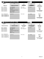 7
7
-
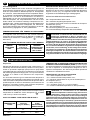 8
8
-
 9
9
-
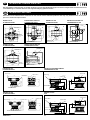 10
10
-
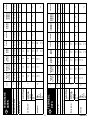 11
11
-
 12
12
-
 13
13
-
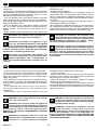 14
14
-
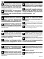 15
15
-
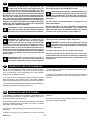 16
16
-
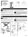 17
17
-
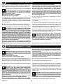 18
18
-
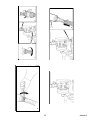 19
19
-
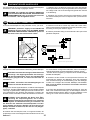 20
20
-
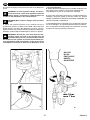 21
21
-
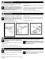 22
22
-
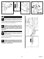 23
23
-
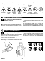 24
24
-
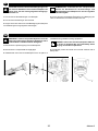 25
25
-
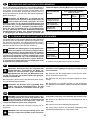 26
26
-
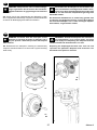 27
27
-
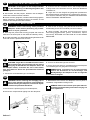 28
28
-
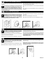 29
29
-
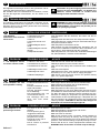 30
30
-
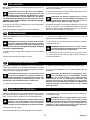 31
31
-
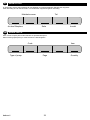 32
32
-
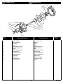 33
33
-
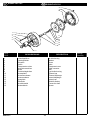 34
34
-
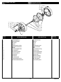 35
35
-
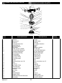 36
36
-
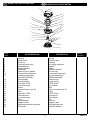 37
37
-
 38
38
-
 39
39
-
 40
40


Debem Equaflux 302 Instructions For Use And Maintenance Manual
- Taper
- Instructions For Use And Maintenance Manual
- Ce manuel convient également à
dans d''autres langues
- italiano: Debem Equaflux 302
- English: Debem Equaflux 302
- Deutsch: Debem Equaflux 302
Autres documents
-
Ingersoll-Rand AF12 Series General Information Manual
-
Beta 1881 Mode d'emploi
-
 SOTERA SS445BX727 Mode d'emploi
-
Graco 3A7214F, SaniForce® Pompe à membrane haute qualité sanitaire pneumatique 1040, Liste de réparation / pièces Le manuel du propriétaire
-
ProMinent DULCO Trans 40/1000 PVDF Operating Instructions Manual
-
AVENTICS Pneumatic piston rod cylinders (ATEX) Le manuel du propriétaire
-
Asco Series WSLPKF Solenoid Manuel utilisateur
-
-
-
