Max Twintier RB441T Instruction Manual And Safety Instructions
- Catégorie
- Outils électroportatifs
- Taper
- Instruction Manual And Safety Instructions

REBAR TYING TOOL
ATADORA DE ARMADURAS DE REFUERZO
OUTIL DE LIGATURE DE BARRES
RB441T
INSTRUCTION MANUAL AND SAFETY INSTRUCTIONS
MANUAL DE INSTRUCCIONES E INSTRUCCIONES DE SEGURIDAD
MODE D'EMPLOI ET CONSIGNES DE SÉCURITÉ
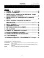
INDEX
ÍNDICE
SOMMAIRE
ENGLISH Page 2 to 18
ESPAÑOL Página 19 a 34
FRANÇAIS Page 35 à 50
Before using the tool, read and understand tool labels and manual. Failure to
follow warnings could result in serious injury. Keep these instructions with the
tool for future reference.
Lea y comprenda las etiquetas y el manual de la herramienta antes de usarla.
El incumplimiento de las advertencias puede provocar lesiones graves.
Conserve estas instrucciones junto con la herramienta para futuras consultas.
Veillez à lire et bien comprendre les étiquettes et le manuel avant d'utiliser cet
outil. Tout manquement au respect des avertissements peut entraîner des
blessures graves. Conservez ces instructions avec l'outil pour toute
consultation ultérieure.
WARNING
ADVERTENCIA
AVERTISSEMENT

2
LOCK
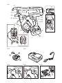
Fig.1
Fig.4
Fig.2 Fig.3
Fig.5 Fig.6
2

3
Fig.7 Fig.8 Fig.9
Fig.10 Fig.11 Fig.12
Fig.13
Fig.14 Fig.15
Fig.16 Fig.17 Fig.18
Fig.19 Fig.20 Fig.21
UNLOCK
45°
3

4
Fig.22 Fig.23 Fig.24
Fig.25
Fig.26 Fig.27
Fig.28 Fig.29
Fig.32
Fig.30
Fig.31
4

5
INDEX
1. NAME OF PARTS......................................................................... 6
2. LIST OF CONTENTS .................................................................... 6
3. GENERAL POWER TOOL SAFETY WARNINGS ....................... 7
4. RB441T SAFETY FEATURES...................................................... 9
5. TOOL SPECIFICATIONS AND TECHNICAL DATA.................. 11
6. TECHNICAL DATA..................................................................... 12
7. PRODUCTION YEAR ................................................................. 12
8. WIRE SPECIFICATION .............................................................. 13
9. APPLICATIONS.......................................................................... 13
10. APPLICABLE REBAR SIZE....................................................... 13
11. BATTERY INSTRUCTIONS........................................................ 14
12. OPERATING INSTRUCTIONS ................................................... 15
13. STORAGE................................................................................... 17
14. WARNING BUZZERS AND PROCEDURES TO FOLLOW ....... 18
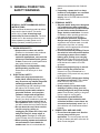
DEFINITIONS OF SIGNAL WORDS
WARNING: Indicates a hazardous situation which, if not avoided, could result in death or serious
injury.
CAUTION: Indicates a hazardous situation which, if not avoided, could result in minor or moderate
injury.
NOTICE: Indicates a property damage message.
ENGLISH
INSTRUCTION MANUAL AND SAFETY INSTRUCTIONS
Original instructions

6
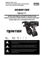
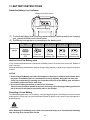
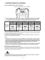
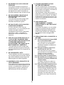
1. NAME OF PARTS
Fig.1
Fig.2
Fig.3
Refer to the JC925 operating and maintenance manual.
Fig.12
Fig.13
2. LIST OF CONTENTS
• MAX Rebar Tying tool / RB441T
• Lithium ion Battery pack / JPL91440A
• Lithium ion Battery charger / JC925
•Power cord
• INSTRUCTION MANUAL AND SAFETY INSTRUCTIONS (This book)
1 Arm
2 Trigger lock
3 Trigger
4 Grip
5 Battery pack
6 Magazine stopper
7 Magazine
8 Release button
9 Release stopper
0 Curl guide
a Center mark
b Serial number
c Torque dial
d LED
e Main switch
f Hook
g Window
h Feeding gear
i Wire guide
j Belt hook
k Pack cap
l Terminal
m Latch
n Magazine cover
o Holding slot

7
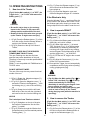
3. GENERAL POWER TOOL
SAFETY WARNINGS
1. WORK AREA SAFETY
• Keep work area clean and well lit.
Cluttered or dark areas invite accidents.
• Do not operate power tools in
explosive atmospheres, such as in the
presence of flammable liquids, gases
or dust. Power tools create sparks which
may ignite the dust or fumes.
• Keep children and bystanders away
while operating a power tool.
Distractions can cause you to lose
control.
2. ELECTRICAL SAFETY
• Power tool plugs must match the
outlet. Never modify the plug in any
way. Do not use any adapter plugs with
earthed (grounded) power tools.
Unmodified plugs and matching outlets
will reduce risk of electric shock.
• Avoid body contact with earthed or
grounded surfaces, such as pipes,
radiators, ranges and refrigerators.
There is an increased risk of electric
shock if your body is earthed or grounded.
• Do not expose power tools to rain or
wet conditions. Water entering a power
tool will increase the risk of electric shock.
• Do not abuse the cord. Never use the
cord for carrying, pulling or
unplugging the power tool. Keep cord
away from heat, oil, sharp edges or
moving parts. Damaged or entangled
cords increase the risk of electric shock.
•
When operating a power tool outdoors,
use an extension cord suitable for
outdoor use.
Use of a cord suitable for
outdoor use reduces the risk of electric
shock.
• If operating a power tool in a damp
location is unavoidable, use a residual
current device (RCD) protected
supply. Use of an RCD reduces the risk
of electric shock.
3. PERSONAL SAFETY
•
Stay alert, watch what you are doing and
use common sense when operating a
power tool. Do not use a power tool while
you are tired or under the influence of
drugs, alcohol or medication.
A moment
of inattention while operating power tools
may result in serious personal injury.
• Use personal protective equipment.
Always wear eye protection. Protective
equipment such as dust mask, non-skid
safety shoes, hard hat, or hearing
protection used for appropriate conditions
will reduce personal injuries.
• Prevent unintentional starting. Ensure
the switch is in the off-position before
connecting to power source and/or
battery pack, picking up or carrying
the tool. Carrying power tools with your
finger on the switch or energising power
tools that have the switch on invites
accidents.
• Remove any adjusting key or wrench
before turning the power tool on.
A wrench or a key left attached to a
rotating part of the power tool may result
in personal injury.
• Do not overreach. Keep proper footing
and balance at all times. This enables
better control of the power tool in
unexpected situations.
• Dress properly. Do not wear loose
clothing or jewelry. Keep your hair,
clothing and gloves away from moving
parts. Loose clothes, jewelry or long hair
can be caught in moving parts.
• If devices are provided for the
connection of dust extraction and
collection facilities, ensure these are
connected and properly used. Use of
dust collection can reduce dust-related
hazards.
4. POWER TOOL USE AND CARE
• Do not force the power tool. Use the
correct power tool for your
application. The correct power tool will
do the job better and safer at the rate for
which it was designed.
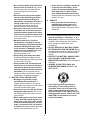
READ ALL SAFETY WARNINGS AND ALL
INSTRUCTIONS.
Failure to follow the warnings and instructions
may result in electric shock, fire and/or
serious injury. Save all warnings and
instructions for future reference. The term
"power tool" in the warnings refers to your
mains-operated (corded) power tool or
battery-operated (cordless) power tool.
WARNING

8
• Do not use the power tool if the switch
does not turn it on and off. Any power
tool that cannot be controlled with the
switch is dangerous and must be
repaired.
• Disconnect the plug from the power
source and/or the battery pack from
the power tool before making any
adjustments, changing accessories, or
storing power tools. Such preventive
safety measures reduce the risk of
starting the power tool accidentally.
• Store idle power tools out of the reach
of children and do not allow persons
unfamiliar with the power tool or these
instructions to operate the power tool.
Power tools are dangerous in the hands
of untrained users.
• Maintain power tools. Check for
misalignment or binding of moving
parts, breakage of parts and any other
condition that may affect the power
tool's operation. If damaged, have the
power tool repaired before use. Many
accidents are caused by poorly
maintained power tools.
• Keep cutting tools sharp and clean.
Properly maintained cutting tools with
sharp cutting edges are less likely to bind
and are easier to control.
• Use the power tool, accessories and
tool bits etc. in accordance with these
instructions, taking into account the
working conditions and the work to be
performed. Use of the power tool for
operations different from those intended
could result in a hazardous situation.
5. BATTERY TOOL USE AND CARE
• Recharge only with the charger
specified by the manufacturer. A
charger that is suitable for one type of
battery pack may create a risk of fire when
used with another battery pack.
• Use power tools only with specifically
designated battery packs. Use of any
other battery packs may create a risk of
injury and fire.
• When battery pack is not in use, keep
it away from other metal objects, like
paper clips, coins, keys, nails, screws
or other small metal objects, that can
make a connection from one terminal
to another. Shorting the battery terminals
together may cause burns or a fire.
• Under abusive conditions, liquid may
be ejected from the battery; avoid
contact. If contact accidentally occurs,
flush with water. If liquid contacts
eyes, additionally seek medical help.
Liquid ejected from the battery may cause
irritation or burns.
6. SERVICE
•
Have your power tool serviced by a
qualified repair person using only
identical replacement parts.
This will
ensure that the safety of the power tool is
maintained.
• Do not use the power tool in the rain, where
water is splashing, in a wet place, or in a
damp place. Using the tool in these or similar
conditions will increase the risk of electric
shock, dangerous malfunction, and
overheating.
• DO NOT DISPOSE OF BATTERY PACKS/
BATTERIES INTO FIRE OR WATER. Battery
packs/batteries should be collected, recycled
or disposed of in an environmental-friendly
manner.
• PROTECT THE BATTERY AGAINST HEAT,
ALSO AGAINST CONTINUOUS SUN
IRRADIATION AND FIRE. There is danger of
explosion.
• CHARGE THE BATTERY PACK IN A
TEMPERATURE RANGE 41°F (5°C) TO
104°F (40°C).
• The product you have purchased is
powered by a Li-ion battery which is
recyclable. At the end of its useful life,
under various state and local laws, it is
illegal to dispose of this battery into your
municipal waste stream. Please call 1-800-
8-BATTERY for information on how to
recycle this battery.

9
4. RB441T SAFETY
FEATURES
1. INSPECT THE PARTS BEFORE
MOUNTING THE BATTERY PACK
• Examine the screws to make sure they are
securely tightened.
Incomplete tightening may result in an
accident or breakage. If a screw is loose,
retighten it completely.
• Inspect parts for damage.
Parts will wear over periods of use. Look
also for missing and defective parts and for
parts of poor quality. If a part must be
replaced or repaired, purchase the
replacement part at the dealer where the
tool was purchased or MAX CO., LTD.
authorized distributors.
Use only genuine authorized replacement
parts.
2. SET THE MAIN SWITCH (FIG.6.e) AT
"OFF", THE TRIGGER LOCK (FIG.6.2)
AT "LOCK" AND REMOVE THE BATTERY
PACK (FIG.6.5), WHEN CHANGING THE
BATTERY PACK, REPLACING OR
ADJUSTING THE TIEWIRE,
ABNORMALITIES OCCUR, AND THE
TOOL IS NOT BEING USED
Leaving the tool switched on in these
situations may cause breakdowns or
damage.
3. KEEP FINGERS AND BODY PARTS
CLEAR BETWEEN THE ARM AND CURL
GUIDE AT ALL TIMES (FIG.23)
Failure to do so may result in serious injury.
4. KEEP FINGERS AND BODY PARTS
AWAY FROM THE TIEWIRE WHEN TOOL
IS IN OPERATION
Failure to do so may result in serious injury.
5. DO NOT POINT THE TOOL AT ANYONE
Personal injury may result if the tool catches
an operator or anyone working near him/her.
While working with the tool, be extremely
careful not to bring hands, legs, and other
body parts near the arm of the tool.
6. WHEN THE TOOL IS NOT IN OPERATION
KEEP YOUR FINGERS OFF THE
TRIGGER
Failure to do so may cause accidental tying,
leading to serious injury.
7. NEVER OPERATE THE TOOL UNDER
ANY ABNORMAL CONDITION
If the tool is not in good working order, or if
any abnormal condition is noticed, switch it off
immediately (set the Main switch at "OFF"),
lock the Trigger and have it examined and
repaired.
8. AFTER BATTERY INSTALLATION IF THE
TOOL OPERATES WITHOUT THE
TRIGGER BEING PULLED OR THE
OPERATOR NOTICES UNUSUAL HEAT,
SMELL, OR SOUND, DISCONTINUE
OPERATION
Failure to do so may lead to serious injury.
Return to dealer for safety inspection.
9. NEVER MODIFY THE TOOL
Modifying the tool will impair performance and
operating safety. Any modification may lead to
serious injury and void the tool warranty.
10. MAINTAIN THE TOOL IN GOOD
OPERATING CONDITION
To secure operating safety and ensure top
performance, keep the tool free of wear and
damage. Also keep the tool's hand grip dry
and clean, especially free of oil and grease.
11. USE ONLY THE AUTHORIZED BATTERY
PACK
If the tool is connected to a power supply
other than the authorized pack, such as a
rechargeable battery, a dry cell, or a storage
battery for use in automobiles, the tool may
be damaged, break down, overheat, or even
catch on fire. Do not connect this tool to any
power supply except the authorized battery
pack.
12. TO ENSURE MAXIMUM PERFORMANCE,
FULLY CHARGE THE BATTERY BEFORE
USE
A new battery pack or one not used for
extended periods may have self-discharged
and thus may need recharging to restore it to
a fully charged condition. Before operating
the tool, make sure to charge the Battery pack
with the designated MAX Battery charger.
13. BATTERY CHARGING PRECAUTION
13-1 Use only MAX Battery charger and
MAX Battery pack.
Failure to do so may cause the Battery
to overheat or catch fire leading to
serious injury.

10
13-2 Charge the Battery from an AC 120V
wall sockets.
Failure to do so may result in
overheating, or inadequate charging
possibly causing serious injury.
13-3 Never use a transformer.
13-4 Never connect the Battery charger to
an engine generator direct-current
power supply.
The charger will break down or be
damaged from burning.
13-5 Avoid charging the Battery pack in
the rain, in a damp place, or where
water is splashing.
Charging a damp or wet Battery pack
will cause an electric shock or a short
circuit that may lead to damage from
burning and even the tool catching on
fire.
13-6 Do not touch the power cord or plug
with a wet hand or glove.
This may cause injury from electric
shock.
13-7 Do not put a cloth or any other cover
on the Battery charger while the
Battery pack is being charged.
This will cause overheating and
damage from burning, or the Charger
may even catch fire.
13-8 Keep the Battery pack and Battery
charger away from heat and flames.
13-9 Do not charge the Battery pack near
flammable materials.
13-10 Charge the Battery pack in a well
ventilated place.
Avoid charging the Battery pack where
it will be in direct sunlight.
13-11 Charge the Battery pack in a
temperature range of 41°F (5°C) to
104°F (40°C).
13-12 Avoid continual use of the Battery
charger.
Rest the Charger for 15 minutes
between charges to avoid functional
trouble with the unit.
13-13 Any objects that block the
ventilation holes or Battery pack
receptacle may cause electric shock
or functional troubles.
Operate the charger free of dust or
other foreign materials.
13-14 Handle the power cord carefully.
Do not carry the Battery charger by its
power cord. Do not use the power cord
to disconnect it from a wall socket; this
will damage the cord and break the
wires or cause a short circuit. Do not let
the power cord contact sharp edged
tools, hot materials, oil, or grease. A
damaged cord must be repaired or
replaced.
13-15 Do not charge non rechargeable
batteries with this charger.
13-16 This charger is not intended for use
by children or disabled persons
without supervisor.
13-17 Children should be supervised to
ensure that they do not play with the
charger.
13-18 Put a Pack cap (Fig.2.k) on the
Terminal (Fig.2.l) of the Battery
pack.
When the Battery pack is not in use, put
a Pack cap on its Terminal to prevent
short circuits.
13-19 Do not let the Terminal (metal
component) of the Battery pack
short-circuit.
A short circuit in the Terminal will
generate a large current, causing to
overheat the Battery pack and become
damaged.
13-20 Do not leave or store the tool in a
vehicle or in direct sunlight during
summer. Leaving the tool in high
temperature conditions may cause
the Battery pack to deteriorate.
13-21 Do not store a fully discharged
Battery pack. If a fully discharged
Battery pack is removed from the
system and left for a long period of
time, it may become damaged.
Recharge the battery immediately
when it has been discharged.
14. WEAR SAFETY GLOVES WHILE
OPERATING THE TOOL
The finish tie has sharp edges. To avoid
serious injures, be careful not to touch the
sharp edges.
15. PRIOR TO USING THE TOOL
(Fig.4 and 5) Make sure that the safety
features function properly. If they do not,
avoid using the tool.

11
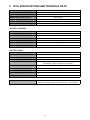
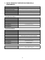
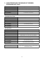
5. TOOL SPECIFICATIONS AND TECHNICAL DATA
<BATTERY CHARGER>
<BATTERY PACK>
PRODUCT DESCRIPTION MAX Rebar Tying tool “TWINTIER”
PRODUCT NO. RB441T
DIMENSIONS (Battery pack included) (H)11-1/2" (295mm) x (W)4-7/8" (125mm) x (L)13" (330mm)
WEIGHT (Battery pack included) 5.6lbs (2.5kg)
BATTERY Lithium ion Battery pack / JPL91440A
OPERATING TEMPERATURE 14°F to 104°F (-10°C to 40°C)
HUMIDITY 80% RH or less
PRODUCT DESCRIPTION Lithium ion Battery charger
PRODUCT NO. JC925
INPUT AC120V 60Hz 2.6A 160W
OUTPUT DC14.4V 7.5A, DC18V 5.4A, DC25.2V 4.5A
WEIGHT 3.3lbs (1.5kg)
OPERATING TEMPERATURE RANGE 41°F to 104°F (5°C to 40°C)
OPERATING HUMIDITY RANGE 80% RH or less
PRODUCT DESCRIPTION Lithium ion Battery pack
PRODUCT NO. JPL91440A
NOMINAL VOLTAGE DC14.4V (3.6V x 4cells)
NOMINAL CAPACITY 3.9Ah (3,900mAh)
CHARGING TIME Quick charging – Approx. 33min.(Approx. 90% of capacity)
Full charging – Approx. 45min.(100% of capacity)
ACCESSORIES Pack cap
WEIGHT 1.1lbs (0.5kg)
CHARGING TEMPERATURE 41°F to 104°F (5°C to 40°C)
OPERATINGTEMPERATURE RANGE 32°F to 104°F (0°C to 40°C)
OPERATING HUMIDITY RANGE 80% RH or less
TIES PER CHARGE Approx. 4,000 ties (*under the following conditions: normal temperature,
unused, full-charged battery and #4 x #4 (13mm x 13mm) rebars)

12
6. TECHNICAL DATA
6-1 NOISE
Measured value according to EN 60745:
A-weighted sound pressure level (LpA): 79 dB
Uncertainty (KpA):3dB
A-weighted sound power level (LWA): 79 dB
Uncertainty (KWA):3dB
6-2 VIBRATION
Measured value according to EN 60745:
Vibration total values (ah): 0.5 m/s
2
Uncertainty (K): 0.1 m/s
2
• The declared vibration emission value has been measured in accordance with the standard test method and may
be used for comparing one tool with another.
• The declared vibration emission value may also be used in a preliminary assessment of exposure.
• The vibration emission during actual use of the power tool can differ from the declared emission value depending
on the ways in which the tool is used.
• Be sure to identify safety measures to protect the operator that are based on an estimation of exposure in the
actual conditions of use (taking account of all parts of the operating cycle such as the times when the tool is
switched off and when it is running idle in addition to the trigger time).
6-3 RADIATED EMISSION 30-1000 MHZ Class A
This is a class A product. In a domestic environment this product may cause radio interference in which case the
user may be required to take adequate measures.
6-4 Overvoltage category - category 1 according to IEC 60664-1
6-5 Pollution degree - degree 4 according to IEC 60664-1
6-6 Design guidelines – Machinery directive annex 1, EN60745-1, EN60745-2-18
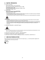
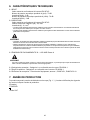
7. PRODUCTION YEAR
This product bears production number in the body (Fig.1.b). The two digits of the number from left
indicates the production year.
WARNING
WARNING
(Example)
17526035D
Year 2017

13
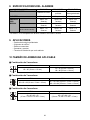
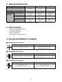
8. WIRE SPECIFICATION
*RB441T is not compatible with TW898 series or TW1525 series.
9. APPLICATIONS
• Precast concrete panel
• Building foundation
• Commercial building
• Road & Bridge
• Floor heating pipe
10.APPLICABLE REBAR SIZE
■ 2 rebars combination
■ 3 rebars combination
■ 4 rebars combination
TIEWIRE TW1061T TW1061T-PC TW1061T-EG
TYPE OF WIRE
Annealed wire Poly-coated wire
Electro-galvanized
wire
DIAMETER 19GA (1.0mm) 19GA (1.1mm) 19GA (1.0mm)
TIES/COIL
#3 × #3 (10 mm × 10 mm)
Approx. 265 ties Approx. 230 ties Approx. 265 ties
#4 × #4 (13 mm × 13 mm)
Approx. 240 ties Approx. 210 ties Approx. 240 ties
#7 × #5 × #5
(22 mm × 16 mm × 16 mm)
Approx. 170 ties Approx. 150 ties Approx. 170 ties
Minimum Maximum
#3 × #3 (10mm × 10mm)
#7 × #7 (22mm × 22mm)
#8 × #6 (25mm × 19mm)
Minimum Maximum
#3 × #3 × #3 (10mm × 10mm × 10mm)
#7 × #5 × #5 (22mm × 16mm × 16mm)
#8 × #4 × #4 (25mm × 13mm × 13mm)
Minimum Maximum
#3 × #3 × #3 × #3
(10mm × 10mm × 10mm × 10mm)
#5 × #5 × #4 × #4
(16mm × 16mm × 13mm × 13mm)

14
11.BATTERY INSTRUCTIONS
About the Battery Level Indicator
(1) To check the battery level (excluding while charging or while operating the charging
tool), press the Battery level check button.
(2) The Battery level gauge is on according to the battery level.
Service Life of the Battery pack
If any condition described below is observed, the Battery pack is at the end of its service life. Replace it
with a new one.
Although the Battery pack has been properly charged (fully charged), a great drop in tying time has been
noticed.
• Do not charge the Battery pack when this happens. If the motor’s rotational speed slows down,
the power of the Battery pack is considered to be nearly depleted. Using the tool more will
cause it to overdischarge, resulting in a shortened service life of the Battery pack and also in
functional trouble of the tool’s main body.
• Do not use a Battery pack when its service life is finished.
This will cause functional trouble in the tool’s main body. Also charging a Battery pack that is
out of service life will lead to functional trouble in the Charger.
Recycling a Li-ion Battery
The MAX battery pack uses a Li-ion battery, it may be illegal to dispose of this Battery into the municipal
waste system. Check with your local solid waste officials for details in your area for recycling options or
proper disposal.
When disposing of the Battery pack, make sure to put a Pack cap on its Terminal (with insulating
tape securing it) to prevent short circuits.
Battery level
gauge
Battery level:
0%
Battery level:
about 0 to 10%
Battery level:
about 10 to 40%
Battery level:
about 40 to 70%
Battery level:
about 70 to 100%
All indicators
OFF
One red
indicator blinks
One red
indicator ON
Two red
indicators ON
Three red
indicators ON
Battery level check button
Battery level gauge
NOTICE
CAUTION

15
12. OPERATING INSTRUCTIONS
1. How to set the Tiewire
(Fig.6) Set the Main switch (e) at "OFF", the
Trigger lock (2) at "LOCK" and remove the
Battery pack (5).
• Be careful not to drop or give a strong
impact to the Tiewire. It may cause the
damage and the malfunction of the tool.
• Beware of the tip of the wire when you pick
up the Tiewire. It might cause an injury.
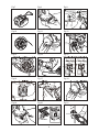
1-1 (Fig.9) Press the Release button (8) of this
tool, and confirm that the Release button is
caught in the Release stopper (9).
1-2 (Fig.10) Stretch out the tip of the wound
Tiewire.
BE SURE TO USE ONLY THE SPECIFIED
TIEWIRE (MAX TW1061T Series).
The use of binding wire that has not been
specified may cause breakdown of this tool.
Therefore, be sure only to use the specified MAX
TW1061T series.
RB441T is not compatible with TW898 series or
TW1525 series.
DO NOT USE RUSTY WIRE.
The use of the rusty wire may cause functional
trouble of the tool.
1-3 (Fig.11) Rotate the Magazine stopper (6 )
45° counterclockwise.
1-4 (Fig.12,13) Open the Magazine cover (n)
and set the Tiewire in the Magazine (7) with
the Holding slot (o) side of the reel facing
up.
1-5 (Fig.14) Grasp the tool with the left hand,
hold the tip of the wire with the right hand,
and remove the wire from the Holding slot.
The 2 wire tips of new Tiewire are twisted.
1-6 (Fig.15) Straighten out the tip of the wire,
and insert the twisted wire into the Wire
guide (i) parallel.
1-7 (Fig.16) Confirm through the Window that
the twisted part of wire has reached past two
Feeding gears (h).
1-8 (Fig.17) Press the Release stopper (9) up,
and confirm that the Release button has
been raised up.
1-9 (Fig.18) Close the Magazine cover and
rotate the Magazine stopper 45° clockwise.
If the Window is dirty
Open the Window (Fig.1.g) and wipe off the dirt
on the inside of the Window with a cloth. Close
the Window again after cleaning to ensure that
foreign objects will not be able to enter the tool.
2. How to operate RB441T
(Fig.6) Set the Main switch (e) at "OFF", the
Trigger lock (2) at "LOCK" and remove the
Battery pack (5).
2-1 (Fig.19) Mount the Battery pack on the tool's
main body until a click is heard.
2-2 (Fig.20) When Main switch (e) is turned
"ON", the Hook (Fig.1.f) of the tip rotates
automatically for initializing, absolutely do
not bring your fingers close to any rotating
and moving part. Set the Main switch at "ON"
and the trigger lock (2) at "UNLOCK".
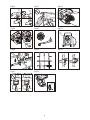
2-3 (Fig.21) Tilt the tool 45° angle to the crossed
rebars.
2-4 (Fig.22) Align the Center mark (a) to the
center of the crossed rebars.
2-5 Once pull the Trigger, the tool automatically
completes a series of tying actions (feeding,
cutting, gripping and tying).
• (Fig.23) When the Main switch (Fig.1.e) is
turned "ON", the Hook (Fig.1.f) of the tip
rotates automatically for initializing,
absolutely do not bring your fingers close
to any rotating and moving part.
• Do not touch any rotating and moving part
such as hook of the tip or the Tiewire
during the tying work (while the machine is
operating).
3. How to remove the Tiewire
(Fig.6) Set the Main switch (e) at "OFF", the
Trigger lock (2) at "LOCK" and remove the
Battery pack (5).
3-1 (Fig.9) Press the Release button (8) of the
tool and confirm that the Release button is
caught in the Release stopper (9).
CAUTION
NOTICE
WARNING

16
3-2 (Fig.11) Rotate the Magazine stopper (6) to
open the Magazine cover.
3-3 (Fig.24) Remove the Tiewire from the
Magazine.
3-4 (Fig.25) Remove the wire with the plastic
piece from the Wire guide.
4. When the Tiewire runs out
(Fig.26) The plastic piece comes off when it is used
up normally, and can be discarded separately as
plastic and metal wire. (About 8" (20cm) remains
after normal use)
(Fig.6) Set the Main switch (e) at "OFF", the
Trigger lock (2) at "LOCK" and remove the Battery
pack (5).
5. Tension adjustment
(Fig.27.c) This dial allows you to adjust wire
tension torque slightly. To increase the tension,
turn it in the counterclockwise. To decrease the
tension, turn it in the clockwise.
6. Auto Power-off feature
This tool has "Auto Power-off" feature, which
saves the power consumption of the Battery
when the tool is not operated.
If the tool is not operated for 30 minutes, the tool
is automatically turned off. When the power is
turned off automatically, turn the Main switch
OFF and ON again to operate the tool.
7. For proper tightness
7-1 (Fig. 21) Tilt the tool 45° angle to the crossed
rebars.
7-2 (Fig.22) Align the Center mark (a) to the
center of the crossed rebars.
7-3 (Fig.28) Apply the tool perpendicularly to the
surface of the crossed rebars.
During tool operation
Do not move the tool during tying operation until
the tool stops tying automatically.
7-4 (Fig.29) Tie in alternate direction.
7-5 (Fig.30) Cross tying.
Bent the knot of the first tie before making
the second tying.
8. How to reload previously used
Tiewire
(Fig.31) Without twisting the 2 wires, insert them
into the Wire guide (i).
9. (Fig.32) How to set and remove
the belt hook to the tool
The belt hook can be installed either on the right
or the left side of the tool.
Installing/Removing the belt hook
(Installing)
Insert the belt hook into the slot on the tool.
Secure it with a screw.
(Removing)
Loosen a screw, and then remove the belt hook.
• When using the belt hook or changing the
position, set the Main switch (e) at "OFF",
the Trigger lock (2) at "LOCK" and remove
the Battery pack (5).
Failure to do so may cause the tool to start
accidentally, which may cause an accident.
• Before using the belt hook, make sure that
the hook is securely installed on the tool.
Using an improperly installed belt hook may
cause personal injury.
• Securely tighten the designated genuine
screw.
If the screw become loose due to vibration, etc.
generated by operation, the loose screw may
cause a dropping accident.
• When using the belt hook, the tool must be
hooked securely to prevent it from falling.
If the tool falls, it could result in an accident.
WARNING

17
13.STORAGE
Do not store the tool in a cold weather
environment. Keep the tool in a warm area.
When not in use, the tool should be stored in a
warm and dry place. Keep out of reach of
children.
REMOVE REEL OF TIEWIRE
When you have finished the Tiewire, remove the
reel from the tool.
STORE THE TOOL
When you have finished tying work or when the
tool will not be used for a while, set the Main
switch (Fig.1.
e
) at "OFF", the Trigger lock
(Fig.1.
2
) at "LOCK" and remove the Battery pack
(Fig.1.
5
). The tool and accessories should be
stored in a well-ventilated dry place where the
temperature will not exceed 104°F (40°C).
The Battery pack with the Pack cap (Fig.2.
k
) to
prevent short circuits should be stored in a well-
ventilated dry place where the temperature will
not exceed 86°F (30°C).

18
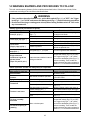
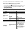
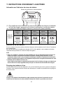
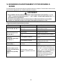
14.WARNING BUZZERS AND PROCEDURES TO FOLLOW
This tool sounds warning buzzers for the conditions described below. If the buzzer sounds, follow
procedures according to the conditions described below.
<Buzzer types and procedures to follow>
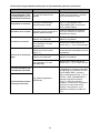
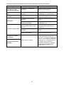
<When no buzzer sounds but malfunction is suspected>
• If the conditions described below occur, set the Main switch (Fig.1.
e
) at "OFF", the Trigger
lock (Fig.1.
2
) at "LOCK" and remove the Battery pack (Fig.1.
5
) before following procedures.
• Do not touch the tying or rotating parts at the tip when setting the Main switch at "ON" under
any circumstances.
Buzzer types Possible cause Procedures to follow
Once (Pi, pi, pi...)
Wire is jammed in the Hook
(Fig.1.f)
Check whether the wire or anything else
is caught in the Hook
Motor is hot Let the tool rest and cool down
Twice (Pipi, pipi, pipi...)
Low battery Charge the Battery pack
Battery pack is not fully inserted Insert the Battery pack properly
Three times
(Pipipi, pipipi, pipipi...)
Tiewire is used up Replace with a new Tiewire
Tiewire is jammed
Open the Magazine cover (Fig.12.n)
and fix the jammed wire
Continuous high pitched
beep (Piii...)
Curl guide (Fig.1.0) is open Confirm supported rebar diameters
Single-short and
continuous high & low
pitched chime
(Pipo / Pii poh Pii poh...)
Internal structure; defect in internal
driving mechanism
Immediately discontinue operation and
set the Main switch (Fig.6.e) at "OFF",
the Trigger lock (Fig.6.2) at "LOCK"
and remove the Battery pack (Fig.6.5)
before consulting. Then contact the
dealer where the tool was purchased or
MAX CO., LTD. authorized distributors.
Symptom Possible cause Procedures to follow
Main switch is "ON" but
does not work
Dead battery
Switch to a new battery and confirm
whether it works
Product does not
function
Auto Power-off feature operated
Try switching the Main switch (Fig.1.e)
from OFF to ON
Tying is not proper Wire is touching rebars while tying Tie so that wire is not touching rebars
Twisted off
Rebar size is not applicable Use with supported rebars diameters
Tension adjustment dial is too tight
Adjust tension adjustment dial
(Fig.1.c)
Tension is too loose
The tied section is not on the
Center mark (Fig.22.a)
Align the Center mark to the center of
the crossed rebars and pull the trigger
Rebar size is not applicable Use with supported rebar diameters
Tension adjustment dial is too
loose
Adjust tension adjustment dial tighter
(Fig.1.c)
Tie form is notably
deformed
Worn or broken parts
Immediately discontinue operation and
set the Main switch (Fig.6.e) at "OFF",
the Trigger lock (Fig.6.2) at "LOCK"
and remove the Battery pack (Fig.6.5)
before consulting. Then contact the
dealer where the tool was purchased or
MAX CO., LTD. authorized distributors.
Increased frequency of
jamming
WARNING

19
ÍNDICE
1. NOMBRE DE LAS PIEZAS ........................................................ 20
2. LISTA DE CONTENIDOS ........................................................... 20
3. ADVERTENCIAS GENERALES DE SEGURIDAD SOBRE
LA HERRAMIENTA ELÉCTRICA............................................... 21
4. ADVERTENCIAS DE SEGURIDAD RELATIVAS A LA
RB441T ....................................................................................... 23
5. DATOS TÉCNICOS Y ESPECIFICACIONES DE LA
HERRAMIENTA .......................................................................... 26
6. DATOS TÉCNICOS .................................................................... 27
7. AÑO DE PRODUCCIÓN ............................................................. 27
8. ESPECIFICACIONES DEL ALAMBRE ...................................... 28
9. APLICACIONES ......................................................................... 28
10. TAMAÑO DE ARMADURA APLICABLE ................................... 28
11. INSTRUCCIONES DE LA BATERÍA .......................................... 29
12. INSTRUCCIONES DE FUNCIONAMIENTO............................... 30
13. ALMACENAMIENTO .................................................................. 32
14. ALARMAS ACÚSTICAS Y PROCEDIMIENTOS A SEGUIR ..... 33
DEFINICIONES DE LAS SEÑALES INDICATIVAS
ADVERTENCIA: indica una situación peligrosa que, si no se evita, puede provocar lesiones graves o
incluso la muerte.
PRECAUCIÓN: indica una situación peligrosa que, si no se evita, puede provocar lesiones leves o
moderadas.
AVISO: indica un mensaje relativo a posibles daños materiales.
ESPAÑOL
MANUAL DE INSTRUCCIONES E INSTRUCCIONES DE SEGURIDAD
Traducción de las
instrucciones originales

20
1. NOMBRE DE LAS PIEZAS
Fig.1
Fig.2
Fig.3
Consulte el manual de funcionamiento y mantenimiento del cargador JC925.
Fig.12
Fig.13
2. LISTA DE CONTENIDOS
• Atadora de armaduras de refuerzo MAX / RB441T
• Paquete de baterías de ion litio / JPL91440A
• Cargador de baterías de ion litio / JC925
• Cable de alimentación eléctrica
• MANUAL DE INSTRUCCIONES E INSTRUCCIONES DE SEGURIDAD (este libro)
1 Brazo
2 Seguro del disparador
3 Disparador
4 Empuñadura
5 Paquete de baterías
6 Bloqueador del
compartimento de bobina
7 Compartimento de bobina
8 Botón de desbloqueo
9 Bloqueo
0 Guía de curvado
a Marca central
b Número de serie
c Disco selector del par
d LED
e Interruptor principal
f Gancho
g Ventanilla
h Engranaje de alimentación
i Guía del alambre
j Gancho para cinturón
k Tapa del paquete
l Terminal
m Cierre
n Cubierta del
compartimento de bobina
o Ranura de sujeción
La page est en cours de chargement...
La page est en cours de chargement...
La page est en cours de chargement...
La page est en cours de chargement...
La page est en cours de chargement...
La page est en cours de chargement...
La page est en cours de chargement...
La page est en cours de chargement...
La page est en cours de chargement...
La page est en cours de chargement...
La page est en cours de chargement...
La page est en cours de chargement...
La page est en cours de chargement...
La page est en cours de chargement...
La page est en cours de chargement...
La page est en cours de chargement...
La page est en cours de chargement...
La page est en cours de chargement...
La page est en cours de chargement...
La page est en cours de chargement...
La page est en cours de chargement...
La page est en cours de chargement...
La page est en cours de chargement...
La page est en cours de chargement...
La page est en cours de chargement...
La page est en cours de chargement...
La page est en cours de chargement...
La page est en cours de chargement...
La page est en cours de chargement...
La page est en cours de chargement...
La page est en cours de chargement...
-
 1
1
-
 2
2
-
 3
3
-
 4
4
-
 5
5
-
 6
6
-
 7
7
-
 8
8
-
 9
9
-
 10
10
-
 11
11
-
 12
12
-
 13
13
-
 14
14
-
 15
15
-
 16
16
-
 17
17
-
 18
18
-
 19
19
-
 20
20
-
 21
21
-
 22
22
-
 23
23
-
 24
24
-
 25
25
-
 26
26
-
 27
27
-
 28
28
-
 29
29
-
 30
30
-
 31
31
-
 32
32
-
 33
33
-
 34
34
-
 35
35
-
 36
36
-
 37
37
-
 38
38
-
 39
39
-
 40
40
-
 41
41
-
 42
42
-
 43
43
-
 44
44
-
 45
45
-
 46
46
-
 47
47
-
 48
48
-
 49
49
-
 50
50
-
 51
51


Max Twintier RB441T Instruction Manual And Safety Instructions
- Catégorie
- Outils électroportatifs
- Taper
- Instruction Manual And Safety Instructions
dans d''autres langues
- English: Max Twintier RB441T
- español: Max Twintier RB441T
Documents connexes
Autres documents
-
Hitachi VB 16Y Safety Instructions And Instruction Manual
-
-
Hitachi DV24DV Manuel utilisateur
-
DeWalt DCD760B TYPE1 Le manuel du propriétaire
-
DeWalt DCN891 Manuel utilisateur
-
-
-
-
Bosch RHS181K Mode d'emploi
-