Rotronic HL-20-CAL Short Instruction Manual
- Taper
- Short Instruction Manual

ROTRONIC AG, CH-8303 Bassersdorf
Tel. +41 44 838 11 44, www.rotronic.com
ROTRONIC Messgeräte GmbH, D-76275 Ettlingen
Tel. +49 7243 383 250, www.rotronic.de
ROTRONIC SARL, 56, F - 77183 Croissy Beaubourg
Tél. +33 1 60 95 07 10, www.rotronic.fr
ROTRONIC Italia srl
, I- 20157 Milano
Tel. +39 2 39 00 71 90, www.rotronic.it
ROTRONIC Instruments (UK) Ltd, West Sussex RH10 9EE
Phone +44 1293 571000, www.rotronic.co.uk
ROTRONIC Instrument Corp, NY 11788, USA
Phone +1 631 427-3898, www.rotronic-usa.com
ROTRONIC South East Asia Pte Ltd, Singapore 339156
Phone +65 6294 6065, www.rotronic.com.sg
ROTRONIC Shanghai Rep. Offi ce, Shanghai 200233, China
Phone +86 40 08162018, www.rotronic.cn
12.0813.9005
SHORT INSTRUCTION MANUAL
Calibration Instructions HL-20
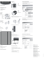
Articles needed for calibration and adjustment
• Calibration unit HL-20-CAL
• Service cable AC3006 (for adjustment via PC)
• Software HW4 (for adjustment via PC)
• Humidity standard
Article overview
Calibration unit
Art. no. HL-20-CAL
Contains: 1x calibration device
2x pads
1x calibration cup
2x screws
1x Allen key
1x retaining bracket
Calibration cups and pads
Art. no. HL-20-CAL-P-C
Contains: 10x calibration cups
20x pads
Pads
Art. no. HL-20-CAL-P
Contains: 20x pads (P)
Accessories
Service cable for connection of the HL-20 to a PC AC3006
HW4 software HW4-E-x
Humidity standard 5 %RH EA05-SCS
Humidity standard 10 %RH EA10-SCS
Humidity standard 11 %RH EA11-SCS
Humidity standard 20 %RH EA20-SCS
Humidity standard 35 %RH EA35-SCS
Humidity standard 50 %RH EA50-SCS
Humidity standard 60 %RH EA60-SCS
Humidity standard 65 %RH EA65-SCS
Humidity standard 75 %RH EA75-SCS
Humidity standard 80 %RH EA80-SCS
Humidity standard 95 %RH EA95-SCS
Calibration accuracy:
± 2 %RH (with 10, 35, 50, 65, 80 %RH calibration solution)
± 2.5 %RH (with 5, 95 %RH calibration solution)
0 %RH not recommended
Follow the instructions for the calibration solutions!
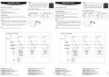
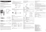
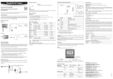
Calibration procedure
1) Unscrew the HL-20 humidity cage.
2) Screw the calibration device on to the HL-20.
3) Place calibration pads in the calibration cup. (Two pads per calibration process). Open the
calibration solution and pour into the calibration cup completely.
4) Insert the calibration cup into the calibration device completely.
5) Mounting of the retaining bracket / Connection to PC
Unscrew the battery cover and push the retaining bracket into the holes.
Connect the AC3006 connection cable to the device.
6) In a constant ambient temperature wait 2½ hours.
7) HL-20 calibration and adjustment procedure (general)
Connect the HL-20 logger to the PC with the AC3006 service cable. Launch HW4.
See the HW4 instruction manual E-M-HW4v3-Main_12 for further information on connecting
the logger to a PC.
The HL-20 adjustment procedure is carried out in two separate steps.
• Acquisition and saving of the calibration points
• Adjustment of the HL-20 on the basis of the saved calibration points
A
Caution!
Do not damage the sensors!
A
Caution!
Do not damage the sensors!
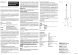
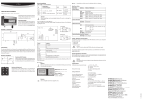
Acquisition and saving of humidity calibration points
In the device tree in HW4 select / HL-20 / “Probe Adjustment” / and then in the menu under
“Settings and Tools” select “%RH Reference”.
Deactivate “Limit the adjustment range” for a standard adjustment.
In Adjust Humidity, enter the value of the humidity standard used at Reference Value and then
confi rm with Save Calibration Point.
As soon as “Save Calibration Point” is pressed, the values are applied in the table on the right side.
Repeat calibration with other humidity values.
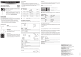
Adjustment of the HL-20 based on the calibration points saved
To adjust the logger on the basis of the calibration data, you must press “Adjust” after entering
all desired calibration points.

ROTRONIC AG, CH-8303 Bassersdorf
Tel. +41 44 838 11 44, www.rotronic.com
ROTRONIC Messgeräte GmbH, D-76275 Ettlingen
Tel. +49 7243 383 250, www.rotronic.de
ROTRONIC SARL, 56, F - 77183 Croissy Beaubourg
Tél. +33 1 60 95 07 10, www.rotronic.fr
ROTRONIC Italia srl
, I- 20157 Milano
Tel. +39 2 39 00 71 90, www.rotronic.it
ROTRONIC Instruments (UK) Ltd, West Sussex RH10 9EE
Phone +44 1293 571000, www.rotronic.co.uk
ROTRONIC Instrument Corp, NY 11788, USA
Phone +1 631 427-3898, www.rotronic-usa.com
ROTRONIC South East Asia Pte Ltd, Singapore 339156
Phone +65 6294 6065, www.rotronic.com.sg
ROTRONIC Shanghai Rep. Offi ce, Shanghai 200233, China
Phone +86 40 08162018, www.rotronic.cn
12.0813.9005
KURZBEDIENUNGSANLEITUNG
Kalibrieranleitung HL-20
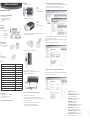
Für die Kalibration, Justage benötigte Artikel:
• Kalibriereinheit HL-20-CAL
• Service Kabel AC3006 (Bei Justage via PC)
• Software HW4 (Bei Justage via PC)
• Feuchtestandard
Artikelübersicht
Kalibriereinheit
Art.-Nr. HL-20-CAL
Beinhaltet: 1x Kalibriervorrichtung
2x Pads
1x Kalibrierbecher
2x Schrauben
1x Imbusschlüssel
1x Haltebügel
Kalibrierbecher und Pads
Art.-Nr. HL-20-CAL-P-C
Beinhaltet: 10x Kalibrierbecher
20x Pads
Pads
Art.-Nr. HL-20-CAL-P
Beinhaltet: 20x Pads (P)
Zubehör
Service Kabel zur Verbindung des HL-20 mit einem PC AC3006
HW4-Software HW4-E-x
Feuchtestandard 5 %rF EA05-SCS
Feuchtestandard 10 %rF EA10-SCS
Feuchtestandard 11 %rF EA11-SCS
Feuchtestandard 20 %rF EA20-SCS
Feuchtestandard 35 %rF EA35-SCS
Feuchtestandard 50 %rF EA50-SCS
Feuchtestandard 60 %rF EA60-SCS
Feuchtestandard 65 %rF EA65-SCS
Feuchtestandard 75 %rF EA75-SCS
Feuchtestandard 80 %rF EA80-SCS
Feuchtestandard 95 %rF EA95-SCS
Kalibriergenauigkeit:
± 2 %rF (bei 10, 35, 50, 65, 80 %r.F. Kalibrierlösung)
± 2,5 %rF (bei 5, 95 %rF. Kalibrierlösung)
0 %rF nicht empfohlen
Bedienungsanleitung der Kalibrierlösungen beachten!
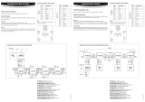
Kalibrierablauf
1) HL-20 Feuchtekorb abschrauben
2) Kalibriervorrichtung auf HL-20 anschrauben
3) Kalibrierpads in Kalibrierbecher legen. (2 Pads pro Kalibriervorgang). Kalibrierlösung öffnen
und komplett in den Kalibrierbecher giessen.
4) Kalibrierbecher in Kalibriervorrichtung komplett einstecken.
5) Montage des Haltebügels / Verbindung zum PC.
Batteriedeckel abschrauben und Haltebügel in die Bohrungen schieben.
Verbindungskabel AC3006 am Gerät anschliessen.
6) Bei gleichbleibender konstanter Umgebungstemperatur 2,5 Std. warten.
7) HL-20 Kalibration und Justierablauf (Generell)
HL-20 Logger via AC3006 Service Kabel mit dem PC verbinden. HW4 starten.
Weitere Informationen zur Verbindung des Logger mit dem PC fi nden Sie in der HW4 Bedie-
nungsanleitung E-M-HW4v3-Main_12.
Der HL-20 Justierablauf wird in zwei getrennten Schritten durchgeführt.
• Aufzeichnen der Kalibrationswerte und deren Abspeicherung
• Justierung des HL-20 aufgrund der gespeicherten Kalibrationswerte
A
Achtung!
Sensoren nicht beschädigen
A
Achtung!
Sensoren nicht beschädigen
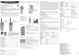
Aufzeichnen der Feuchte Kalibrationswerte und deren Abspeicherung
In der HW4 im Gerätebaum / HL-20 / Fühler „Justieren“ auswählen / Im Menü unter Extras
„Feuchte“ auswählen und „Feuchte Referenz“ auszuwählen.
„Justierbereich verwenden“ für die standardmässige Justierung deaktivieren
Unter Feuchte Justieren im Referenzwert, den Wert der verwendeten Feuchtestandard eingeben
um danach mit Messwert erfassen zu bestätigen.
Sobald „Messwert erfassen“ gedrückt wird, werden die Werte auf der rechten Seite in die Tabelle
übernommen.
Wiederholung der Kalibration mit anderen Feuchte Werten.
Justierung des HL-20 aufgrund der gespeicherten Kalibrationswerte
Um den Logger Aufgrund der Kalibrationsdaten zu justieren muss nach erfassen aller gewünschten
Kalibrierwerte „Justieren starten“ gedrückt werden.

ROTRONIC AG, CH-8303 Bassersdorf
Tel. +41 44 838 11 44, www.rotronic.com
ROTRONIC Messgeräte GmbH, D-76275 Ettlingen
Tel. +49 7243 383 250, www.rotronic.de
ROTRONIC SARL, 56, F - 77183 Croissy Beaubourg
Tél. +33 1 60 95 07 10, www.rotronic.fr
ROTRONIC Italia srl
, I- 20157 Milano
Tel. +39 2 39 00 71 90, www.rotronic.it
ROTRONIC Instruments (UK) Ltd, West Sussex RH10 9EE
Phone +44 1293 571000, www.rotronic.co.uk
ROTRONIC Instrument Corp, NY 11788, USA
Phone +1 631 427-3898, www.rotronic-usa.com
ROTRONIC South East Asia Pte Ltd, Singapore 339156
Phone +65 6294 6065, www.rotronic.com.sg
ROTRONIC Shanghai Rep. Offi ce, Shanghai 200233, China
Phone +86 40 08162018, www.rotronic.cn
12.0813.9005
MODE D'EMPLOI ABRÉGÉ
Manuel d’étalonnage HL-20
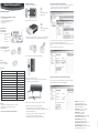
Articles nécessaires pour l’étalonnage ou l’ajustage:
• Unité d’étalonnage HL-20-CAL
• Câble de service AC3006 (pour l’ajustage par PC)
• Logiciel HW4 (pour l’ajustage par PC)
• Étalon d’humidité
Aperçu des articles
Unité d’étalonnage
No d’article HL-20-CAL
Contenu: 1 dispositif d’étalonnage
2 tampons
1 cuvette d’étalonnage
2 vis
1 clé à 6 pans
1 étrier de support
Cuvette d’étalonnage et tampons
No d’article HL-20-CAL-P-C
Contenu: 10 cuvettes d’étalonnage
20 tampons
Tampons
No d’article HL-20-CAL-P
Contenu: 20 tampons (P)
Accessoires
Câble de service pour la liaison de l’HL-20 à un PC AC3006
Logiciel HW4 HW4-E-x
Étalon d’humidité 5 %HR EA05-SCS
Étalon d’humidité 10 %HR EA10-SCS
Étalon d’humidité 11 %HR EA11-SCS
Étalon d’humidité 20 %HR EA20-SCS
Étalon d’humidité 35 %HR EA35-SCS
Étalon d’humidité 50 %HR EA50-SCS
Étalon d’humidité 60 %HR EA60-SCS
Étalon d’humidité 65 %HR EA65-SCS
Étalon d’humidité 75 %HR EA75-SCS
Étalon d’humidité 80 %HR EA80-SCS
Étalon d’humidité 95 %HR EA95-SCS
Étalonnage
± 2 %HR (avec des solutions d’étalonnage de 10, 35, 50, 65, 80 %HR)
± 2,5 %HR (avec des solutions d’étalonnage de 5, 95 %HR)
0 %HR déconseillé
Tenir compte du manuel d’utilisation des solutions d’étalonnage!
Déroulement de l’étalonnage
1) Dévisser la corbeille d’humidité de l’HL-20
2) Visser le dispositif d’étalonnage sur l’HL-20
3) Placer les tampons d’étalonnage dans la cuvette. (2 tampons par processus d’étalonnage).
Ouvrir la solution d’étalonnage et la verser entièrement dans la cuvette d’étalonnage.
4) Introduire complètement la cuvette dans le dispositif d’étalonnage.
5) Montage de l’étrier de support / Liaison au PC.
Dévisser le couvercle des batteries et glisser l’étrier de support dans les perforations.
Relier le câble de raccordement AC3006 à l’appareil.
6) Attendre 2,5 heures à une température d’environnement maintenue constante.
7) Étalonnage de l’HL-20 et déroulement de l’ajustage (généralités)
Relier le logger HL-20 avec le câble de service AC3006 au PC. Démarrer HW4.
Vous trouverez d’autres informations concernant la liaison du logger à un PC dans le manuel
d’utilisation d’HW4 E-M-HW4v3-Main_12.
Le déroulement de l’ajustage de l’HL-20 est effectué en deux étapes séparées:
• Enregistrement des valeurs d’étalonnage et de leur sauvegarde
• Ajustage de l’HL-20 sur la base des données d’étalonnages enregistrées
A
Attention!
Veiller à ne pas endommager les
éléments sensibles
A
Attention!
Veiller à ne pas endommager les
éléments sensibles
Enregistrement et sauvegarde des valeurs d’étalonnage
Sélectionner «Ajuster» sur HW4 / HL-20 / Capteur, dans l’arborescence des appareils / Dans
le menu, sélectionner sous «Extras», «Humidité» et «Humidité de référence».
Désactiver «Utiliser le secteur d’ajustage» pour un ajustage standard
Entrer la valeur de l’étalon d’humidité utilisé sous ’ «Ajuster l’humidité» dans les valeur de
référence, pour ensuite confi rmer avec «Saisir la valeur de mesure».
Les valeurs, sur le côté droit du tableau, sont chargées dès que «Saisir la valeur de mesure» est
pressé.
Répéter l’étalonnage avec d’autres valeurs d’humidité.
Ajustage de l’HL-20 par rapport aux valeurs d’étalonnage enregistrées
Pour ajuster le logger par rapport aux données d’étalonnage, il suffi t de presser sur «Démarrer
l’ajustage» après avoir saisi toutes les données d’étalonnage désirées.

ROTRONIC AG, CH-8303 Bassersdorf
Tel. +41 44 838 11 44, www.rotronic.com
ROTRONIC Messgeräte GmbH, D-76275 Ettlingen
Tel. +49 7243 383 250, www.rotronic.de
ROTRONIC SARL, 56, F - 77183 Croissy Beaubourg
Tél. +33 1 60 95 07 10, www.rotronic.fr
ROTRONIC Italia srl
, I- 20157 Milano
Tel. +39 2 39 00 71 90, www.rotronic.it
ROTRONIC Instruments (UK) Ltd, West Sussex RH10 9EE
Phone +44 1293 571000, www.rotronic.co.uk
ROTRONIC Instrument Corp, NY 11788, USA
Phone +1 631 427-3898, www.rotronic-usa.com
ROTRONIC South East Asia Pte Ltd, Singapore 339156
Phone +65 6294 6065, www.rotronic.com.sg
ROTRONIC Shanghai Rep. Offi ce, Shanghai 200233, China
Phone +86 40 08162018, www.rotronic.cn
12.0813.9005
MANUALE D'ISTRUZIONI BREVE
Istruzioni di calibrazione HL-20
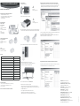
Articoli necessari per la calibrazione, regolazione:
• Dispositivo di calibrazione HL-20-CAL
• Cavo di servizio AC3006 (per la regolazione tramite PC)
• Software HW4 (per la regolazione tramite PC)
• Standard di umidità
Panoramica articolo
Dispos. di calibraz.
Cod. art. HL-20-CAL
Comprende:
1x dispositivo di calibrazione
2x feltrini
1x contenitore di calibrazione
2x viti
1x chiave a brugola
1x staffa di fi ssaggio
Contenitore di calibrazione e feltrini
Cod. art. HL-20-CAL-P-C
Comprende:
10x contenitori di calibrazione
20x feltrini
Feltrini
Cod. art. HL-20-CAL-P
Comprende: 20x feltrini (P)
Accessori
Cavo di servizio per il collegamento dell'HL-20 ad un PC AC3006
Software HW4 HW4-E-x
Standard di umidità 5 %ur EA05-SCS
Standard di umidità 10 %ur EA10-SCS
Standard di umidità 11 %ur EA11-SCS
Standard di umidità 20 %ur EA20-SCS
Standard di umidità 35 %ur EA35-SCS
Standard di umidità 50 %ur EA50-SCS
Standard di umidità 60 %ur EA60-SCS
Standard di umidità 65 %ur EA65-SCS
Standard di umidità 75 %ur EA75-SCS
Standard di umidità 80 %ur EA80-SCS
Standard di umidità 95 %ur EA95-SCS
Precisione di calibrazione:
± 2 %ur (con soluzione di calibrazione da 10, 35, 50, 65, 80 %ur)
± 2,5 %ur (con soluzione di calibrazione da 5, 95 %ur)
0 %ur non consigliata
Osservare le istruzioni d'uso delle soluzioni di calibrazione!
Ciclo di calibrazione
1) Svitare la gabbia dell'HL-20
2) Avvitare il dispositivo di calibrazione sull'HL-20
3) Porre i feltrini di calibrazione nei relativi contenitori. (2 feltrini per ogni procedura di calibrazione).
Aprire la soluzione di calibrazione, versandola completamente nel contenitore di calibrazione.
4) Inserire completamente nel dispositivo di calibrazione il contenitore di calibrazione.
5) Montaggio della staffa di fi ssaggio / Connessione al PC.
Svitare il coperchio della batteria e inserire la staffa di fi ssaggio nei fori.
Collegare il cavo di collegamento AC3006 allo strumento.
6) In caso di temperatura ambiente costante attendere 2,5 ore.
7) Calibrazione HL-20 e ciclo di regolazione (generale)
Collegare il registratore HL-20 al PC tramite il cavo di servizio AC3006. Lanciare l'HW4.
Per maggiori informazioni sul collegamento del registratore al PC, consultare le istruzioni d'uso
dell'HW4 E-M-HW4v3-Main_12.
Il ciclo di regolazione dell'HL-20 si effettua in due fasi distinte.
• Registrazione dei valori di calibrazione e relativa memorizzazione
• Regolazione dell'HL-20 sulla scorta dei valori di calibrazione memorizzati
A
Attenzione!
Non danneggiare i sensori
A
Attenzione!
Non danneggiare i sensori
Registrazione dei valori di calibrazione di umidità e relativa memorizzazione
Nell'HW4 selezionare nel menu "Strumenti e Gruppi" / HL-20 / "Correzione Taratura Sonda" /
Nel menu, alla voce "Confi gurazione HW4" selezionare "Umidità" per selezionare "Rif. %ur".
Per la regolazione nella versione standard disattivare "Limitare range di correzione"
Alla voce "Correggi Umidità", inserire in "Valore di Rif." il valore degli standard di umidità utilizzati
per confermare successivamente con "Acquisire Valore di Rif.".
Non appena cliccato su "Acquisire Valore di Rif.", i valori appariranno nella tabella a destra.
Ripetizione della calibrazione con altri valori di umidità.
Regolazione dell'HL-20 sulla scorta dei valori di calibrazione memorizzati
Per regolare il registratore sulla scorta dei dati di calibrazione, si dovrà cliccare su "Correggi"
successivamente alla rilevazione di tutti i valori di calibrazione richiesti.
-
 1
1
-
 2
2
-
 3
3
-
 4
4


Rotronic HL-20-CAL Short Instruction Manual
- Taper
- Short Instruction Manual
dans d''autres langues
- italiano: Rotronic HL-20-CAL
- English: Rotronic HL-20-CAL
- Deutsch: Rotronic HL-20-CAL
Documents connexes
-
 Rotronic AC3011 Masterbox Short Instruction Manual
-
 Rotronic GTS Short Instruction Manual
-
 Rotronic AC3021 Short Instruction Manual
-
Rotronic HM4 Short Instruction Manual
-
 Rotronic HP21 Short Instruction Manual
-
 Rotronic HC2-Ix25 Short Instruction Manual
-
 Rotronic XB OEM Short Instruction Manual
-
 Rotronic PF4 Short Instruction Manual
-
 Rotronic TF5 Short Instruction Manual
-
 Rotronic HF5NEW Manuel utilisateur


