Rotronic AC3021 Short Instruction Manual
- Taper
- Short Instruction Manual

12.0945.0002
12.0945.0002
ROTRONIC AG, CH-8303 Bassersdorf
Tel. +41 44 838 11 44, www.rotronic.com
ROTRONIC Messgeräte GmbH, D-76275 Ettlingen
Tel. +49 7243 383 250, Fax +49 7243 383 260, www.rotronic.de
ROTRONIC SARL, 56, F - 77183 Croissy Beaubourg
Tél. +33 1 60 95 07 10, www.rotronic.fr
ROTRONIC Italia srl, I- 20157 Milano
Tel. +39 2 39 00 71 90, Fax (+39) 02 33 27 62 99, www.rotronic.it
ROTRONIC Instruments (UK) Ltd, Crompton Fields,
Phone +44 1293 571000, www.rotronic.co.uk
ROTRONIC Instrument Corp, NY 11788, USA
Phone +1 631 427-3898, www.rotronic-usa.com
ROTRONIC South East Asia Pte Ltd, Singapore 339156
Phone +65 6294 6065, www.rotronic.com.sg
ROTRONIC Shanghai Rep. Office, Shanghai 200233, China
Phone +86 40 08162018, www.rotronic.cn
Bitte lesen Sie diese Kurzanleitung genau durch, bevor Sie die Box installieren.
Allgemeine Beschreibung
Die Verteilerbox AC3021 wurde entwickelt um in ein RS-485 Netzwerk einzubinden und
eine möglichst einfache und schnelle Installation zu gewährleisten.
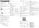
Montage
Die Verteilerbox wird mit den mitgelieferten Schrauben an eine Wand montiert.
Ablauf: Bohren Sie zwei Löcher in einem Abstand von 90mm. Setzen Sie die beiden mitgelie-
ferten Dübel ein. Befestigen Sie nun mit den beiden Schauben die Verteilerbox an die Wand.
Kabeleinführung
Die Verteilerbox bietet insgesamt 8 Kabeleinführungen. Stechen Sie mit einer Aale in die Vor-
markierten Kabeleinführungen um eine genügend grosse Öffnung für das Kabel zu erhalten.
Stossen Sie nun das Kabel durch das Loch und schliessen es an der gewünschten Klemme an.
Please read these short instructions carefully before installing the box.
General Description
The junction box AC3021 was designed to simplify RS-485 networks and guarantees a quick
and easy installation.
Installation
The junction box can be mounted with the delivered screws on a wall.
Procedure: Drill two holes at a distance of 90mm. Insert the supplied wall plugs. Fix the
junction box to the wall with the two screws.
Cabling
The junction box offers a total of 8 cable entries. Enlarge the marked cable entries with an
awl in order to get a large enough opening for the cable. Push the cable through the hole
and connect it to the terminal block.
KURZBEDIENUNGSANLEITUNG
SHORT INSTRUCTION MANUAL
VERTEILER-BOX AC3021DISTIRIBUTON BOX AC3021
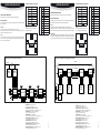
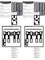
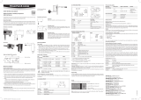
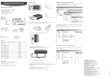
Elektrische Installation und Anschlüsse
Electrical installation and connections
OUTPUT
Block Designation
K1-1 V +
K1-2 GND
K1-3 D +
K1-4 D –
K3-1 Shield
K3-2 Shield
K2-1 V +
K2-2 GND
K2-3 D +
K2-4 D –
K4-1 Shield
K4-2 Shield
AUSGANG
Block Bezeichnung
K1-1 V +
K1-2 GND
K1-3 D +
K1-4 D –
K3-1 Schirm
K3-2 Schirm
K2-1 V +
K2-2 GND
K2-3 D +
K2-4 D –
K4-1 Schirm
K4-2 Schirm
INPUT
Block Designation
K6-1 V +
K6-2 GND
K6-3 D +
K6-4 D –
K6-5 Shield
K6-6 Shield
K5-1 Shield
K5-2
EINGANG
Block Bezeichnung
K6-1 V +
K6-2 GND
K6-3 D +
K6-4 D –
K6-5 Schirm
K6-6 Schirm
K5-1 Schirm
K5-2
K 1
K 2
1
2
3
4
1
2
3
4
K5
1
2
K 3
2 1
1
2
3
4
5
6
K 4
2 1
B1
K 6
K 1
K 2
1
2
3
4
1
2
3
4
K5
1
2
K 3
2 1
1
2
3
4
5
6
K 4
2 1
B1
K 6
Note
B1: For a termination (end box) please close
the jumper on the PCB.
Hinweis
B1: Für eine Terminierung (End Dose) schlies-
sen Sie den Jumper auf der Printplatte an.
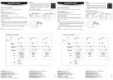
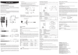
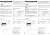
Example of an RS-485 network with HF8 Transmitters
Beispiel eines RS-485 Netzwerk mit HygroFlex8 Messumformer
HF8
AC3021AC3021AC3021
Ethernet
HF8
K3:4
K3:3
K3:2
K3:1
AC3021
GND
D+
D-
T
V+
GND
D+
D-
V+
TTT
GND
D+
D-
V+
GND
D+
D-
V+
GND
D+
D-
V+
PC
~
GND
D+
D-
V+
Unit
GND
D+
D-
V+
GND
V+
D+
D-
Shield
D-
D+
GND
AC3021
V+
AC3021
Shield
D-
D+
GND
Shield
D-
D+
GND
AC3021
Shield
D-
D+
GND
V+
AC3021
Master
AC3011
Shield
D-
D+
GND
V+
Slave
HF5
Shield
D-
D+
GND
V+
Slave
HF5
Shield
D-
D+
GND
V+
Slave
HF5
Shield
D-
D+
GND
V+
V+ V+
Power supply 1 V+
GND
Power supply 2 V+
GND
V+ not wired
100m
1000m
PC
with
HW4
Ethernet

12.0845.0002
12.0845.0002
ROTRONIC AG, CH-8303 Bassersdorf
Tel. +41 44 838 11 44, www.rotronic.com
ROTRONIC Messgeräte GmbH, D-76275 Ettlingen
Tel. +49 7243 383 250, Fax +49 7243 383 260, www.rotronic.de
ROTRONIC SARL, 56, F - 77183 Croissy Beaubourg
Tél. +33 1 60 95 07 10, www.rotronic.fr
ROTRONIC Italia srl, I- 20157 Milano
Tel. +39 2 39 00 71 90, Fax (+39) 02 33 27 62 99, www.rotronic.it
ROTRONIC Instruments (UK) Ltd, Crompton Fields,
Phone +44 1293 571000, www.rotronic.co.uk
ROTRONIC Instrument Corp, NY 11788, USA
Phone +1 631 427-3898, www.rotronic-usa.com
ROTRONIC South East Asia Pte Ltd, Singapore 339156
Phone +65 6294 6065, www.rotronic.com.sg
ROTRONIC Shanghai Rep. Office, Shanghai 200233, China
Phone +86 40 08162018, www.rotronic.cn
Veuillez lire Veuillez lire attentivement ce manuel abrégé avant d’installer le boîtier.
Description générale
Le boîtier de répartition AC 3021 a été conçu pour être intégré à un réseau RS-485 et pour
garantir une installation simple et rapide.
Montage
Le boîtier de répartition doit être monté sur une paroi avec les vis de xation fournies.
Montage: percez deux trous à une distance de 90mm l’un de l’autre. Introduisez les deux
chevilles fournies. Fixez le boîtier de répartition au mur avec les vis.
Introduction des câbles
Le boîtier de répartition dispose de 8 passes-câbles. Enfoncez un poinçon dans le passe-câble
à l’endroit pré-perforé et agrandissez l’ouverture au diamètre voulu pour le passage du câble.
Passez ensuite le câble par la perforation et raccordez-le à la borne désirée.
MODE D'EMPLOI ABRÉGÉ
BOÎTIER DE RÉPARTITION AC3021
Installation électrique et raccordements
Remarque
B1: pour une terminaison (prise finale),
raccordez un cavalier à la platine.
Prima di installare la scatola, si prega di leggere la presente guida rapida.
Informazioni generali
La scatola di connessione AC3021 è stata sviluppata per le connessioni ad una rete RS-485
e per garantire un'installazione estremamente facile e rapida.
Montaggio
La scatola di connessione si monta a parete con l'ausilio delle viti in dotazione.
Sequenza: praticare due fori ad una distanza di 90mm. Inserirvi entrambi i tasselli forniti
in dotazione. A questo punto ssare alla parete con le due viti la scatola di connessione.
Passaggio cavi
La scatola di connessione presenta complessivamente 8 passaggi per i cavi. Con un punte-
ruolo incidere i passaggi premarcati per i cavi, così da ottenere aperture sufcientemente
ampie per il loro passaggio. A questo punto, spingere i cavi attraverso i fori, per poi collegarli
ai morsetti richiesti.
MANUALE D'ISTRUZIONI BREVE
SCATOLA DI CONNESSIONE AC3021
Installazione e collegamenti elettrici
Nota
B1: per la presa terminale collegare il
ponticello al circuito stampato.
SORTIE
Bornes Description
K1-1 V +
K1-2 GND
K1-3 D +
K1-4 D –
K3-1 Protection
K3-2 Protection
K2-1 V +
K2-2 GND
K2-3 D +
K2-4 D –
K4-1 Protection
K4-2 Protection
ENTRÉE
Bornes Description
K6-1 V +
K6-2 GND
K6-3 D +
K6-4 D –
K6-5 Protection
K6-6 Protection
K5-1 Protection
K5-2
K 1
K 2
1
2
3
4
1
2
3
4
K5
1
2
K 3
2 1
1
2
3
4
5
6
K 4
2 1
B1
K 6
K 1
K 2
1
2
3
4
1
2
3
4
K5
1
2
K 3
2 1
1
2
3
4
5
6
K 4
2 1
B1
K 6
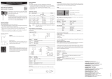
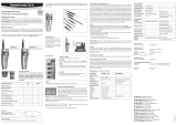
Exemple d’un réseau RS-485 avec un transmetteur de mesure HygroFlex8
Esempio di rete RS-485 con trasmettitore HygroFlex8
Shield
D-
D+
GND
AC3021
V+
AC3021
Shield
D-
D+
GND
Shield
D-
D+
GND
AC3021
Shield
D-
D+
GND
V+
AC3021
Master
AC3011
Shield
D-
D+
GND
V+
Slave
HF5
Shield
D-
D+
GND
V+
Slave
HF5
Shield
D-
D+
GND
V+
Slave
HF5
Shield
D-
D+
GND
V+
V+ V+
Power supply 1 V+
GND
Power supply 2 V+
GND
V+ not wired
100m
1000m
PC
with
HW4
Ethernet
Shield
D-
D+
GND
AC3021
V+
AC3021
Shield
D-
D+
GND
Shield
D-
D+
GND
AC3021
Shield
D-
D+
GND
V+
AC3021
Master
AC3011
Shield
D-
D+
GND
V+
Slave
HF5
Shield
D-
D+
GND
V+
Slave
HF5
Shield
D-
D+
GND
V+
Slave
HF5
Shield
D-
D+
GND
V+
V+ V+
Power supply 1 V+
GND
Power supply 2 V+
GND
V+ not wired
100m
1000m
PC
with
HW4
Ethernet
USCITA
Morsetto Denominazione
K1-1 V +
K1-2 GND
K1-3 D +
K1-4 D –
K3-1 Schirm
K3-2 Schirm
K2-1 V +
K2-2 GND
K2-3 D +
K2-4 D –
K4-1 Schirm
K4-2 Schirm
INGRESSO
Morsetto Denominazione
K6-1 V +
K6-2 GND
K6-3 D +
K6-4 D –
K6-5 Schermatura
K6-6 Schermatura
K5-1 Schermatura
K5-2
-
 1
1
-
 2
2


Rotronic AC3021 Short Instruction Manual
- Taper
- Short Instruction Manual
dans d''autres langues
- italiano: Rotronic AC3021
- English: Rotronic AC3021
- Deutsch: Rotronic AC3021
Documents connexes
-
 Rotronic AC3011 Masterbox Short Instruction Manual
-
 Rotronic TF5 Short Instruction Manual
-
 Rotronic HF5NEW Manuel utilisateur
-
 Rotronic HF4 Manuel utilisateur
-
 Rotronic XB OEM Short Instruction Manual
-
 Rotronic hf5 Manuel utilisateur
-
 Rotronic HC2-Ix25 Short Instruction Manual
-
 Rotronic HL-20-CAL Short Instruction Manual
-
 Rotronic LOG-HC2 Universal Datalogger Short Instruction Manual
-
 Rotronic HP21 Short Instruction Manual


