Caleffi NA10897 - 145 FLOWMATIC PICV Mode d'emploi
- Taper
- Mode d'emploi

FLOWMATIC® Pressure Independent Control Valve (PICV)
The pressure independent control valve is a device composed of an automatic
flow rate regulator and a control valve with optional actuator. The device can
adjust flow rate and keep it constant in the presence of changing differential
pressure conditions of the circuit in which it is installed.
Flow rate is adjusted in two different ways:
-manually on the automatic flow rate regulator, to restrict the maximum value.
-automatically by the control valve in combination with a proportional (0–10 V) or
ON/OFF actuator, in accordance with the thermal load requirements of the circuit
to be controlled.
The pressure independent control valve (PICV) is supplied complete with pressure
test ports for confirming pressure differential and flow rate.
NA10897
Product range
Function
Technical characteristics
Materials:
Body: DZR corrosion-resistant brass CW602N
Headwork: DZR corrosion-resistant brass CW602N
Control stem and piston: stainless steel AISI 303
Seat:
- (G90): DZR corrosion-resistant CW602N
- (1G8, 3G5, 5G3): PTFE
- (7G9, 13G, 16G): stainless steel AISI 303
stainless steel AISI 302
peroxide-cured EPDM
PA6G30
PA6
1/2”, 3/4”, 1”
Springs:
Seals:
Pre-adjustment indicator:
Knob:
Connections:
Main:
Actuators:
M30 p.1.5
Pressure test ports: 1/4” F (ISO 228-1) with cap
© Copyright 2023 Caleffi
www.caleffi.com
145 Series pressure independent control valve (PICV), with PT ports:
sizes 1/2”, 3/4”, 1” NPT female, sweat, press
1
Performance:
Medium: water, glycol solutions
Max. percentage of glycol: 50 %
Max. working pressure:
360 psi ( 25 bar ) / 200 psi ( 14 bar ) press
Max. differential pressure with actuator: 58 psi
Working temperature range: 4 – 248 °F (-20 - 120 °C)
Nominal ∆p control range: 3.6 - 58 psi (0.2 - 4 bar)
Max flow rate regulation:
(G90): 0.09-0.90 gpm (0.34–3.4 l/min)
(1G8): 0.35-1.75 gpm (1.3–6.6 l/min)
(3G5): 0.35-3.5 gpm (1.3–13.2 l/min)
(5G3): 0.53-5.3 gpm (2.0–20 l/min)
(7G9): 0.79-7.9 gpm (3.0–30.3 l/min)
(13G): 1.3-13 gpm (5.0–50 l/min)
(16G): 1.6-16 gpm (6.25–62.5 l/min)
Accuracy: ± 5% of set-point
Leakage: 0.01% (class V)
145 series

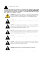
SAFETY INSTRUCTION
WARNING: This product can expose you to chemicals including lead, which
is known to the State of California to cause cancer and birth defects or other
reproductive harm. For more information go to www.P65Warning.ca.gov.
CAUTION: All work must be performed by qualified personnel trained in the
proper application, installation, and maintenance of systems in accordance
with all applicable codes ordinances.
CAUTION: Over-tightening and breakage can occur with the use of Teflon®
pipe joint compounds. Teflon® provides lubricity so that care must be
exercised not to over-tighten joints. Failure to follow these instructions could
result in property damage and / or personal injury.
CAUTION: System fluids under pressure or temperature can be hazardous.
Be sure the pressure has been reduced to zero and the system temperature
is below 100℉ (38℉). Failure to follow these instructions could result in
property damage and/or personal injury.
CAUTION: Clean the pipes of any debris, rust, incrustations, welding slag
and any other contaminants. For optimal operation, air in the system must
be removed.
CAUTION: If the 145 valve is not installed, commissioned and maintained
properly, according to the instructions contained in this manual, it may not
operate correctly and may endanger the user.
CAUTION: Make sure that all the connecting pipework is water tight.
Caleffi shall not be liable for damages resulting from stress corrosion, misapplication or
misuse of its products..
This safety alert symbol will be used in this manual to draw attention to safety related
instructions. When used, the safety alert symbol means ATTENTION! BECOME ALERT!
YOUR SAFETY IS INVOLVED! FAILURE TO FOLLOW THESE INSTRUCTIONS
MAY RESULT IN A SAFETY HAZARD.
2

3
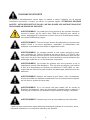
CONSIGNE DE SÉCURITÉ
AVERTISSEMENT: Ce produit peut vous exposer à des produits chimiques
comme le plomb, qui est connu dans l’État de Californie pour causer le
cancer, dommages à la naissance ou autre. Pour plus d’informations rendez-
vous www.P65Warnings.ca.gov.
AVERTISSEMENT: Tous les travaux doivent être effectués par du personnel
qualifié formé à la bonne application, installation et maintenance des
systèmes conformément aux codes et règlements locaux.
AVERTISSEMENT: Un serrage excessif et une rupture peuvent survenir
avec l’utilisation de Teflon® composés de joint de tuyau. Le Teflon® offre
un pouvoir lubrifiant de sorte que les soins doivent être exercé pour ne pas
trop serrer les joints. Non-respect de ces instructions pourrait entraîner des
dommages matériels et / ou des blessures corporelles.
AVERTISSEMENT: Les liquides du système sont sous pression ou de la
température peivent être dangereux. Être sûr que la pression a été réduite
à zéro et la température du système est inférieure à 100℉ (38℉). Le non-
respect de ces instructions peut entrainer des dommages matériels et/ou des
blessures.
AVERTISSEMENT: Nettoyer les tuyaux de tout debris, roille, incrustations,
scories de soudure et d’autres contaminants.Pour un fonctionnement optimal,
de l’air dans le system doit etre retire.
AVERTISSEMENT: Si le 145 vanne n’est pas installe, mis en service et
Entretenu correctement, selon les instructions contenues dans ce manuel, il
Peut ne pas fonctionner correctement et peut mettre en danger l’utilisateur.
AVERTISSEMENT: S’assurer que tous les raccordements sont étanches.
Caleffi ne pourra etre tenue responsable des dommages resultant de la corrosion, d’une
mauvaise utilisation ou une mauvaise utilisation des produits.
Ce symbole d’avertissement servira dans ce manuel à attirer l’attention sur la sécurité
concernant instructions. Lorsqu’il est utilisé, ce symbole signifie. ATTENTION! DEVENEZ
ALERTE ! VOTRE SÉCURITÉ EST EN JEU ! NE PAS SUIVRE CES INSTRUCTIONS PEUT
PROVOQUER UN RISQUE DE SECURITE.

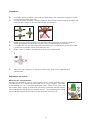
Installation:
℉Assembly and disassembly of the valve should always be carried out while the system
is cold and not under pressure.
℉The valve without actuator can be installed in any position. When using an actuator the
valve can be installed in any position except upside down.
℉Indoor use only. When installed with actuator consult actuator instruction sheet for
details on ambient temperature, humidity and fluid temperature restrictions.
℉If installed with an actuator and inside an enclosure it is important to ensure that there
is adequate ventilation inside the enclosure itself.
℉When valve is installed, the direction of flow must be observed.
℉Valve must be installed in a manner to allow easy access for inspection and
maintenance.
Maximum flow rate adjustment
Unscrew the protective cap by hand to gain access to the maximum flow
rate locking nut (10), which can be turned with a 19 mm wrench. Attached
to the locking nut is a 10-position graduated scale. Refer to the “Flow rate
adjustment table” below to determine the correct numerical position based
on the design flow rate of the circuit being served. Turn the locking nut, lining
up the desired numerical position with the notch on the valve (12).
Adjustment procedure:
10
12
4

Flow rate confirmation
During operation the differential pressure across the valve is observed using a manometer
connected to upstream (A) and downstream (B) test ports on the valve. If the differential pressure
is greater than the minimum ∆P of the valve at the selected flow rate and less than the maximum
∆P, the valve is supplying the flow rate for which it has been set up. Refer to the “Flow rate
adjustment table” to determine minimum ∆P. Maximum ∆P is 58 psi.
Shut-off
With the protective cap installed, manual shut-off is possible with the integrated knob. Turn
clockwise to shut-off flow, turn counterclockwise to open.
Code
locking nut
colour/range G
Meas.
Flow rate (m
3
/h)
DN
Adjustment position
12345678910
Flow rate (m
3
/h)
Flow rate (m
3
/h)
Flow rate (m
3
/h)
Flow rate (m
3
/h)
Flow rate (m
3
/h)
Flow rate (m
3
/h)
Flow rate (m
3
/h)
Flow rate (m
3
/h)
Flow rate (m
3
/h)
Dp min (kPa)
Dp min (kPa)
Dp min (kPa)
Dp min (kPa)
Dp min (kPa)
Dp min (kPa)
Dp min (kPa)
Dp min (kPa)
Dp min (kPa)
Dp min (kPa)
0,08
25
0,16
25
0,08
25
0,16
25
0,08
25
0,16
25
0,24
25
0,08
25
0,16
25
0,24
25
0,08
25
0,16
25
0,24
25
0,36
35
0,36
35
0,6
35
0,36
35
0,6
35
0,12
25,5
0,24
25,5
0,12
25,5
0,24
25,5
0,12
25,5
0,24
25,5
0,36
25,5
0,12
25,5
0,24
25,5
0,36
25,5
0,12
25,5
0,24
25,5
0,36
25,5
0,54
35
0,54
35
0,9
35
0,54
35
0,9
35
0,16
26
0,32
26
0,16
26
0,32
26
0,16
26
0,32
26
0,48
26
0,16
26
0,32
26
0,48
26
0,16
26
0,32
26
0,48
26
0,72
35
0,72
35
1,2
35
0,72
35
1,5
35
0,2
26
0,40
26
0,2
26
0,40
26
0,2
26
0,40
26
0,6
26
0,2
26
0,40
26
0,6
26
0,2
26
0,40
26
0,6
26
0,9
35
0,9
35
1,5
35
0,9
35
1,5
35
0,24
26,5
0,48
27
0,24
26,5
0,48
27
0,24
26,5
0,48
26
0,72
26,5
0,24
26,5
0,48
26
0,72
26,5
0,24
26,5
0,48
26
0,72
26,5
1,08
28
1,08
28
1,8
35
1,08
28
1,8
35
0,28
26,5
0,56
27,5
0,28
26,5
0,56
27,5
0,28
26,5
0,56
26,5
0,84
26,5
0,28
26,5
0,56
26,5
0,84
26,5
0,28
26,5
0,56
26,5
0,84
26,5
1,26
25
1,26
25
2,1
35
1,26
25
2,1
35
0,32
27
0,64
28
0,32
27
0,64
28
0,32
27
0,64
26,5
0,96
27
0,32
27
0,64
26,5
0,96
27
0,32
27
0,64
26,5
0,96
27
1,44
25
1,44
25
2,4
35
1,44
25
2,4
35
0,36
27
0,72
28,5
0,36
27
0,72
28,5
0,36
27
0,72
27
1,08
27,5
0,36
27
0,72
27
1,08
27,5
0,36
27
0,72
27
1,08
27,5
1,62
25
1,62
25
2,7
35
1,62
25
2,7
35
0,40
27
0,8
29
0,40
27
0,8
29
0,40
27
0,8
27
1,2
28
0,40
27
0,8
27
1,2
28
0,40
27
0,8
27
1,2
28
1,8
25
1,8
25
3
35
1,8
25
3
35
-
-
0,08
25
-
-
0,08
25
-
-
0,08
25
0,12
25
-
-
0,08
25
0,12
25
-
-
0,08
25
0,12
25
0,18
35
0,18
35
0,3
35
0,18
35
0,3
35
Flow rate (m
3
/h)
Flow rate (m
3
/h)
Flow rate (m
3
/h)
Flow rate (m
3
/h)
Flow rate (m
3
/h)
Flow rate (m
3
/h)
Flow rate (m
3
/h)
Flow rate (m
3
/h)
Dp min (kPa)
Dp min (kPa)
Dp min (kPa)
Dp min (kPa)
Dp min (kPa)
Dp min (kPa)
Dp min (kPa)
Dp min (kPa)
145430 H40
145430 H80
145440 H40
145440 H80
145550 H40
145550 H80
145550 1H2
145560 H40
145560 H80
145560 1H2
145552 H40
145552 H80
145552 1H2
145550 1H8
145660 1H8
145660 3H0
145770 1H8
145770 3H0
15
15
15
15
20
20
20
20
20
20
20
20
20
25
25
25
25
25
3/8”
3/8”
1/2”
1/2”
3/4”
3/4”
3/4”
1”
1”
1”
0,08–0,40
m3/h
0,08–0,80
m3/h
0,08–0,40
m3/h
0,08–0,80
m3/h
0,08–0,40
m3/h
0,08–0,80
m3/h
0,12–1,20
m3/h
0,08–0,40
m3/h
0,08–0,80
m3/h
0,12–1,20
m3/h
0,08–0,40
m3/h
0,08–0,80
m3/h
0,12–1,20
m3/h
0,18–1,80
m3/h
0,18–1,80
m3/h
0,30–3,00
m3/h
0,18–1,80
m3/h
0,30–3,00
m3/h
3/4”
Euroconus
3/4”
Euroconus
3/4”
3/4”
1”
1”
1 1/4”
1 1/4”
Euroconus
2.0-20.0 (l/min)
123456 78 10
1.30-6.60 (l/min)
0.35-1.75 (GPM)
145... G90
145... 1G8
145... 3G5
145... 5G3
145... 7G9
145... 13G
0.34-3.40 (l/min)
0.09-0.90 (GPM)
(kPa)
(psi)
1.30-13.2 (l/min)
0.35-3.50 (GPM)
0.53-5.30 (GPM)
0.79- 7.9 (GPM)
1.30-13 (GPM)
9
0.67
0.18
25
3.6
1.30
0.35
25
3.6
2.67
0.70
25
3.6
4.00
1.06
25
3.6
6.00
1.60
35
5.1
10.00
2.60
35
5.1
12.33
3.30
48
6.96
1.00
0.27
25
3.6
2.00
0.53
25,5
3.7
4.00
1.05
25,5
3.7
6.00
1.59
25,5
3.7
9.00
2.40
35
5.1
15.00
3.90
35
5.1
18.5
4.95
48
6.96
1.33
0.36
25
3.6
2.67
0.70
26
3.8
5.33
1.40
26
3.8
8.00
2.12
26
3.8
12.00
3.20
35
5.1
20.00
5.20
35
5.1
24.67
6.60
48
6.96
1.67
0.45
25
3.6
3.33
0.88
26
3.8
6.67
1.75
26
3.8
10.00
2.65
26
3.8
15.00
4.00
35
5.1
25.00
6.50
35
5.1
30.83
8.25
45
6.53
2.00
0.54
25
3.6
4.00
1.05
26,5
3,8
8.00
2.10
27
3.9
12.00
3.18
26,5
3.8
18.00
4.80
28
4.1
30.00
7.80
35
5.1
37.00
9.90
45
6.53
2.33
0.63
25,5
3.7
4.67
1.23
26,5
3.8
9.33
2.45
27,5
4.0
14.00
3.71
26,5
3.8
21.00
5.60
25
3.6
35.00
9.10
35
5.1
43.17
11.55
43
6.24
2.67
0.72
25,5
3.7
5.33
1.40
27
3.9
10.67
2.80
28
4.1
16.00
4.24
27
3.9
24.00
6.40
25
3.6
40.00
10.40
35
5.1
49.33
13.20
43
6.24
3.00
0.81
26
3.8
6.00
1.58
27
3.9
12.00
3.15
28,5
4.1
18.00
4.77
27,5
4.0
27.00
7.20
25
3.6
45.00
11.70
35
5.1
55.50
14.85
43
6.24
3.40
0.90
26
3.8
6.60
1.75
27
3.9
13.20
3.50
29
4.2
20.00
5.30
28
4.1
30.30
8.00
25
3.6
50.00
13.00
35
5.1
62.50
16.50
43
6.24
3.0-30.30 (l/min)
5.0-50.0 (l/min)
0.34
0.09
25
3.6
–
–
–
–
1.30
0.35
25
3.6
2.00
0.53
25
3.6
3.00
0.80
35
5.1
5.00
1.30
35
5.1
6.25
1.65
48
6.96
∆p min
(kPa)
(psi)
∆p min
(kPa)
(psi)
∆p min
(kPa)
(psi)
∆p min
(kPa)
(psi)
∆p min
(kPa)
(psi)
Code
locking nut color
flow range G
∆p min
Adjustment position
145... 16G 1.6-16 (GPM)
6.25-62.50 (l/min)
(kPa)
(psi)
∆p min
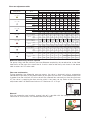
Minimum differential pressure required
For pump sizing, add the minimum pressure difference required by the served emitter to the fixed
head losses of the most flow starved circuit. Use this value to find the ∆p min shown in the above
table to select the 145 series code
Flow rate adjustment table
5

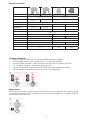
Optional Actuators:
Actuator installation:
• Protective cap on valve must be removed before actuator installation.
• Do not supply power to the actuator until it is installed on the valve.
• For 6565 Series actuators, thread clip onto valve fully and fit actuator to clip (N).
• For 145 Series actuators, thread onto valve fully (M).
• Connect the actuator to external controls (BMS or similar) to operate actuator.
• Consult actuator instruction sheet for details on wiring and setup
Maintenance:
After final commissioning, release the air that has built up at the top of the valve body by using
a screwdriver to loosen screw at bottom of valve, without fully removing. Re-tighten screw at
the end of the procedure (O).
6
Code 145018 145013 656524 656504
Type Proportional Thermo-Electric
Fail Position Fail in place
closed or open Fail-in-place Normally Closed
Electic Supply 24V AC/DC
Power Consumption 2.5 VA (AC) ; 1.5W (DC) 1.2 W 1 W
Control Signal 0(2)-10VDC or
0(4)-20mA
0(2)-10VDC or
0(4)-20mA
0-10 VDC ON / OFF
Open & Close Time ~ 35 sec (*) ~200 sec ~ 240 sec
Protection class NEMA 3 (IP54)
Ambient temp range 32 - 120˚F (0 50˚C) 32 - 140˚F (0 - 60˚C)
Feedback signal 0 - 10V 0 - 10V ---
Supply cable length 78 inches (2 m) 39 inches (1 m)
Connection M30 x 1.5 M30 x 1.5 (quick-coupling)
Force 36 lbf (160 N) 28 lbf (125 N) 23 lbf (100 N)
Max. differential pressure 58 psid (4 bar)
Starting current 1.54A 320mA 300mA
*auto stoke detection

NOTES
7

Caleffi North America, Inc.
3883 West Milwaukee Road
Milwaukee, WI 53208
T: 414.238.2360 F: 414.238.2366
NOTES
8
7-2023
-
 1
1
-
 2
2
-
 3
3
-
 4
4
-
 5
5
-
 6
6
-
 7
7
-
 8
8


Caleffi NA10897 - 145 FLOWMATIC PICV Mode d'emploi
- Taper
- Mode d'emploi
dans d''autres langues
Documents connexes
-
Caleffi NA10923 - 149 FLOWMATIC Coil Kit Mode d'emploi
-
-
-
-
-
-
Caleffi North America 38476 Guide d'installation
Autres documents
-
Johnson Controls VP140LCA Installation Instructions Manual
-
Baxi LUNA HT 330 Fiche technique
-
Grundfos CUE Series Installation And Operating Instructions Manual
-
Wayne Jet Pump Water Systems Shallow Well Le manuel du propriétaire
-
-
Johnson Controls VP10JDB Series Manuel utilisateur
-
Fleck 4600 Le manuel du propriétaire
-
 AquaPower AQC 8-2 Guide d'installation
