
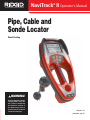
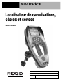
Pipe, Cable and
Sonde Locator
• Français – 33
• Castellano – pág. 67
WARNING!
Read this Operator’s Manual
carefully before using this
tool. Failure to understand
and follow the contents of
this manual may result in
electrical shock, fire and/or
serious personal injury.
NaviTrack
®
II Operator’s Manual
Patent Pending

Ridge Tool Company
ii
Table of Contents
Recording Form for Machine Serial Number and Software Version .........................................................................................................1
General Safety Information
Work Area Safety........................................................................................................................................................................................2
Electrical Safety ..........................................................................................................................................................................................2
Battery Precautions.......................................................................................................................................................................................
Personal Safety...........................................................................................................................................................................................2
NaviTrack II Use and Care..........................................................................................................................................................................3
Service ........................................................................................................................................................................................................3
Specific Safety Information
Important.....................................................................................................................................................................................................3
Specifications and Standard Equipment
Specifications..............................................................................................................................................................................................3
Standard Equipment ...................................................................................................................................................................................4
Optional Equipment.....................................................................................................................................................................................4
Frequencies ................................................................................................................................................................................................4
Icon Legend ................................................................................................................................................................................................5
NaviTrack II Components ..............................................................................................................................................................................6
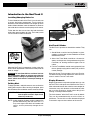
Introduction to the NaviTrack II
Installing/Changing Batteries ......................................................................................................................................................................7
Folding Mast................................................................................................................................................................................................7
NaviTrack II Modes .....................................................................................................................................................................................7
Display Elements ........................................................................................................................................................................................7
Set Up .......................................................................................................................................................................................................10
Sonde Locating
Location Methods......................................................................................................................................................................................13
Tilted Sondes ............................................................................................................................................................................................14
Measuring Depth (Sonde Mode)...............................................................................................................................................................14
Clipping (Sonde Mode) .............................................................................................................................................................................14
Line Tracing
Active Line Tracing....................................................................................................................................................................................16
Passive Line Tracing.................................................................................................................................................................................18
Operating Tips for Active Line and Passive Line Tracing .........................................................................................................................19
Measuring Depth (Tracing Modes)............................................................................................................................................................20
Clipping (Tracing Modes)..........................................................................................................................................................................20
Menus and Settings .....................................................................................................................................................................................20
Optional Features within the Display Elements Menu...............................................................................................................................22
Frequencies Selection Control .................................................................................................................................................................23
Information Screen and Restoring Defaults ..............................................................................................................................................24
Menu Tree.................................................................................................................................................................................................25
A Better Way of Locating ............................................................................................................................................................................25
Advantages of the Omnidirectional Antenna.............................................................................................................................................26
Proximity Signal ........................................................................................................................................................................................27
“Informational” Locating ............................................................................................................................................................................27
Getting the Most Out Of the NaviTrack II
More on Informational Locating.................................................................................................................................................................27
Notes on Accuracy....................................................................................................................................................................................28
NaviTrack II Maintenance Instructions
Transportation and Storage ......................................................................................................................................................................29
Installing/Using Accessories .....................................................................................................................................................................29
Maintenance and Cleaning .......................................................................................................................................................................29
Locating Faulty Components ....................................................................................................................................................................29
Service and Repair.......................................................................................................................................................................................30
Glossary – Definitions
.................................................................................................................................................................................30
Troubleshooting...........................................................................................................................................................................................32
Lifetime Warranty ..........................................................................................................................................................................Back Cover
NaviTrack
®
II

Pipe, Cable and
Sonde Locator
NaviTrack
®
II
Patent Pending
NaviTrack
®
II
Record Serial Number below and retain product serial number for your records.
See information screen for serial number and software version.
Serial No.
Software Version

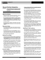
• Gloves should always be worn for health and safe-
ty reasons. Sewer lines are unsanitary and may con-
tain harmful bacteria and viruses.
• Do not overreach. Keep proper footing and balance
at all times. Proper footing and balance enables bet-
ter control of the tool in unexpected situations.
• Use safety equipment. Always wear eye protection.
Dust mask, non-skid safety shoes, hard hat, or hearing
protection must be used for appropriate conditions.
• Use proper accessories. Do not place this product on
any unstable cart or surface. The product may fall
causing serious injury to a child or adult or serious
damage to the product.
• Prevent object and liquid entry. Never spill liquid of
any kind on the product. Liquid increases the risk of
electrical shock and damage to the product.
• Avoid Traffic. Pay close attention to moving vehi-
cles when using on or near roadways. Wear visible
clothing or reflector vests. Such precautions may
prevent serious injury.
NaviTrack II Use and Care
• Use equipment only as directed. Do not operate
the NaviTrack II unless the owner’s manual has been
read and proper training has been completed.
• Do not immerse the antennas in water. Store in a
dry place. Such measures reduce the risk of electric
shock and instrument damage.
• Store idle equipment out of the reach of children
and other untrained persons. Equipment is dan-
gerous in the hands of untrained users.
• Maintain the instrument with care. Properly main-
tained diagnostic instruments are less likely to cause in-
jury.
• Check for breakage of parts, and any other con-
ditions that may affect the NaviTrack II’s operation.
If damaged, have the instrument serviced before using.
Many accidents are caused by poorly maintained
tools.
• Use only accessories that are recommended by
the manufacturer for the NaviTrack II. Accessories
that may be suitable for one instrument may become
hazardous when used on another.
• Keep handles dry and clean; free from oil and
grease. Allows for better control of the instrument.
• Protect against excessive heat. The product should
be situated away from heat sources such as radiators,
Ridge Tool Company
2
General Safety Information
WARNING! Read and understand all instructions. Failure
to follow all instructions listed below may re-
sult in electric shock, fire and/or serious per-
sonal injury.
SAVE THESE INSTRUCTIONS!
Work Area Safety
• Keep your work area clean and well lit. Cluttered
benches and dark areas may cause accidents.
• Do not operate electrical devices or power tools in
explosive atmospheres, such as in the presence of
flammable liquids, gases, or heavy dust. Electrical
devices or power tools create sparks which may ignite
the dust or fumes.
• Keep bystanders, children, and visitors away while
operating a tool. Distractions can cause you to lose
control.
Electrical Safety
• Do not operate the system with electrical compo-
nents removed. Exposure to internal parts increases
the risk of injury.
• Avoid exposure to rain or wet conditions. Keep bat-
tery out of direct contact with water. Water entering
electrical devices increases the risk of electric shock.
• Do not probe high voltage line.
Battery Precautions
• Use only the size and type of battery specified. Do
not mix cell types (e.g. do not use alkaline with
rechargeable). Do not use partly discharged and fully
charged cells together (e.g. do not mix old and new).
• Recharge batteries with charging units specified
by the battery manufacturer. Using an improper
charger can overheat and rupture the battery.
• Properly dispose of the batteries. Exposure to high
temperatures can cause the battery to explode, so
do not dispose of in a fire. Some countries have reg-
ulations concerning battery disposal. Please follow
all applicable regulations.
Personal Safety
• Stay alert, watch what you are doing and use com-
mon sense. Do not use diagnostic tool while tired or
under the influence of drugs, alcohol, or medications.
A moment of inattention while operating tools may
result in serious personal injury.
NaviTrack
®
II

Ridge Tool Company
3
heat registers, stoves or other products (including
amplifiers) that produce heat.
Service
• Diagnostic instrument service must be performed
only by qualified repair personnel. Service or main-
tenance performed by unqualified repair personnel
could result in injury.
• When servicing a tool, use only identical replace-
ment parts. Follow instructions in the Maintenance
Section of this manual. Use of unauthorized parts or
failure to follow maintenance instructions may create a
risk of electrical shock or injury.
• Follow instructions for changing accessories.
Accidents are caused by poorly maintained tools.
• Provide proper cleaning. Remove battery before
cleaning. Do not use liquid cleaners or aerosol clean-
ers. Use a damp cloth for cleaning.
• Conduct a safety check. Upon completion of any ser-
vice or repair of this product, ask the service technician
to perform safety checks to determine that the product
is in proper operating condition.
• Damage to the product that requires service. Refer
servicing to qualified service personnel under any of
the following conditions:
• If liquid has been spilled or objects have fallen into
product;
• If product does not operate normally by following the
operating instructions;
• If the product has been dropped or damaged in
any way;
• When the product exhibits a distinct change in per-
formance.
CAUTION
Remove batteries entirely before shipping.
If you have any questions regarding the service or repair
of this machine, call or write to:
Ridge Tool Company
Technical Service Department
400 Clark Street
Elyria, Ohio 44035-6001
Tel: (800) 519-3456
E-mail: [email protected]
On the Web: www.ridgid.com or
www.navitrack.com
In any correspondence, please give all the information
shown on the nameplate of your tool including model
number and serial number and software version
(See
Figure 1)
.
Specific Safety Information
WARNING
Read this operator’s manual carefully before using
the NaviTrack II. Failure to understand and follow
the contents of this manual may result in electrical
shock, fire and/or severe personal injury.
Call the Ridge Tool Company, Technical Service De-
partment at (800) 519-3456 if you have any questions.
Important Notice
The NaviTrack II is a diagnostic tool that senses elec-
tromagnetic fields emitted by objects underground. It is
meant to aide the user in locating these objects by rec-
ognizing characteristics of the field lines and displaying
them on the screen. As electromagnetic field lines can be
distorted and interfered with, it is important to verify the
location of underground objects before digging.
Several utilities may be underground in the same
area. Be sure to follow local guidelines and one call
service procedures.
Exposing the utility is the only way to verify it’s ex-
istence, location and depth.
Ridge Tool Co., its affiliates and suppliers, will not be
liable for any injury or any direct, indirect, incidental
or consequential damages sustained or incurred by
reason of the use of the NaviTrack II.
Specifications and
Standard Equipment
Specifications
Weight w/batteries.........5.2 lbs. (2.35 kg.)
Weight w/o batteries......4.5 lbs. (2.04 kg.)
Dimensions:
Length ...........................15.0″ (38.1 cm.)
Width .............................7.2″ (18.3 cm.)
Height (Extended) .........31.1″ (78.9 cm.)
Height (Closed) .............19.1″ (48.5 cm.)
Power Source................4 C-size batteries, 1.5V
Alkaline (ANSI/NEDA 14A,
IEC LR14) or 1.2V NiMH or
NiCad rechargeable batteries
Power Rating:................6V, 550mA
NaviTrack
®
II

Ridge Tool Company
4
Signal Strength..............Non-linear in function. (2000
is 10x higher than 1000, 3000
is 10x higher then 2000, etc.)
Operating Environment
Temperature................-4°F to 122°F (-20°C to 50°C)
Humidity ......................5% to 95% RH
Storage Temperature .....-4°F to 140°F (-20°C to 60°C)
Default Settings
The default settings for the locator are:
• Measured Depth units = Feet & Inches,
• Volume = 2 (two settings above mute),
• Backlight = Auto
• 512 Hz (Sonde) Default Mode
Optional Settings
The optional settings for the locator are:
• Measured Depth units = Meters,
• Volume = 0 (mute) to 5,
• Backlight = On, Off
• Mode: Active Line Trace, Passive Line Trace
Standard Equipment
Optional Equipment
NaviTrack
®
II
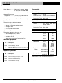
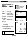
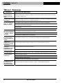
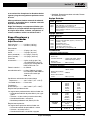
Nominal and Exact Frequency Values (NaviTrack II)
Sonde 16 Hz 16
512 Hz 512
640 Hz 640
850 Hz 850
8 kHz 8192
16 kHz 16384
33 kHz 32768
Active Line 128 Hz 128
Trace 1 kHz 1,024
8 kHz 8,192
33 kHz 32,768
200 kHz 200000
262 kHz 262,144
Passive Line 50 Hz
Trace (9th harmonic) 450
60 Hz
(9th harmonic) 540 Hz
(European) 93 kHz 93,696.0
93 kHz -B 93,622.9
(See note on 93 kHz Frequencies on page 17.)
Catalog
No. Description
14818 NaviTrack Line Transmitter – 10 Watt
20168 NaviTrack Brick Transmitter – 5 Watt
20503 Inductive Clamp (4.75″)
16728 Remote Transmitter (Sonde)
19793 Float Sonde (Package of 2)
12543 Surface Markers and Clip
Catalog
No. Description
96967 NaviTrack II Locator
12543 Surface Markers and Clip
22388 Molded Carrying Case
— Operator’s Manual (Downloadable @ www.navitrack.com)
— Quick-Start Guide (Downloadable @ www.navitrack.com)
Frequencies
Default Frequencies
Sonde ........................512Hz
Active Line Trace.......128Hz 1kHz, 8kHz, 33kHz,
262kHz (European: 93kHz)
Passive Line Trace....60Hz (9th)
Optional Frequencies
Sonde ........................16Hz, 640Hz, 850Hz, 8kHz,
16kHz, 33kHz
Active Line Trace.......200kHz
Passive Line Trace....50Hz (9th)

Ridge Tool Company
5
NaviTrack
®
II
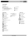
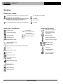
Icon Legend
Display Icons
Keypad Icons
Sonde Frequency
Active Trace Frequency
Proximity Signal
Signal Strength
Battery Level
Measured Depth/Distance
Signal Angle Indicator
(Sonde Mode)
Signal Angle Indicator (Trace Mode)
Pole Icon
Sonde Equator Line
Up Key – Menu Navigation
Select Key – Menu Select
Sonde Mode: Force Depth/Re-center Audio
Line Trace Mode: Force Map Display on if Signal
Strength is centered, Re-center Audio
Power ON/OFF Key
Menu Key
Frequency Key
Sound Key
Audio Level
Down Key – Menu Navigation
Menu Icons
Low Battery Warning
(Flashing)
Level Pointer
(Signal Strength)
Tracing Line
(Lower Antenna Signal)
No Trace Signal Present
No Sonde Signal Present
Water Mark
(Signal Strength)
Distortion Line
(Upper Antenna Signal)
Factory Default Reset
Menu Check Box
Signal Clipping
Tools Menu
Backlight Settings
Screen Contrast Adjust
Screen Setup
Menu Setup
Information Screen
Auto Exit Menu
Timeout Counter
Exit/Go Up One Level
(Press Menu Key)

Ridge Tool Company
6
NaviTrack
®
II
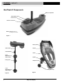
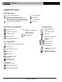
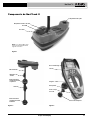
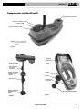
Figure 3
NaviTrack II Components
Battery Compartment
Serial Number Label
USB Connector
Serial Port Connector
NOTE: USB/Serial Ports are
for loading new software
Antenna Mast
Surface Markers
Upper
Omnidirectional
Antenna Node
Folding Joint
Lower
Omnidirectional
Antenna Node
Figure 2
Figure 1
Display Screen
Keypad
Handle
Speaker
Headphone Jack
Folding Mast Snap

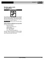
Figure 5 – Folding Antenna Mast and Release Button
NaviTrack II Modes
The NaviTrack II operates in three distinct modes. They
are:
1. Sonde Mode, used for locating Sondes in pipes,
conduits, or tunnels that are non-conductive or cannot
otherwise be traced.
2. Active Line Trace Mode, used when a chosen fre-
quency can be put onto a long conductor using a line
transmitter, for locating conductive pipes, lines or
cables.
3. Passive Trace Mode, used for tracing electrical lines
that are already carrying 60 Hz current (U.S.) or 50 Hz
current (Europe).
Note that the two Tracing modes, Active and Passive,
are identical except for the frequencies used. No trans-
mitter is used in Passive Trace mode.
Display Elements
Beginning operators or experienced operators can use
the NaviTrack II with equal ease. While the NaviTrack II
offers advanced features that make the most complex lo-
cate easier, many of its features can be turned off or hid-
den to make the display simpler when doing basic
locating in uncomplicated situations.
The “basic features” of the NaviTrack II are on by default.
They can be customized easily to suit the user’s re-
quirements. The use of the various elements displayed
is covered in separate later sections of the manual.
Ridge Tool Company
7
NaviTrack
®
II
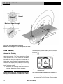
Introduction to the NaviTrack II
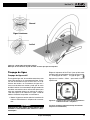
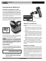
Installing/Changing Batteries
To install batteries into the NaviTrack II turn the unit over
to access the battery compartment. Turn the knob on
the battery cover counter-clockwise. Pull straight up on the
knob to remove the door. Insert the batteries as shown on
the inside decal and make sure they drop to full contact.
Fit the door into the case and turn the knob clockwise
while lightly pressing down to close. The battery cover
can be installed in either orientation.
Figure 4 – Battery Case
When the NaviTrack II is powered on, it takes a few sec-
onds to check the batteries. Until then the battery level will
show as “empty”.
Do not allow debris or moisture into bat-
tery compartment. Debris or moisture may short the
battery contacts, leading to rapid discharge of the bat-
teries, which could result in electrolyte leakage or
risk of fire.
Folding Mast
To begin operation, unfold the antenna mast and lock the
folding joint into place. When locating is complete, press
the red release lever to fold the antenna mast for storage.
NOTE! Avoid dragging the lower antenna node on the
ground while locating with the NaviTrack II. It
may cause signal noise which will interfere with
results, and may eventually damage the an-
tenna.
CAUTION
Release Button
IMPORTANT! Do not snap or whip the NaviTrack II
mast to open or close it. Open it and
close it by hand only.

Ridge Tool Company
8
NaviTrack
®
II
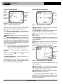
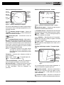
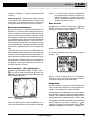
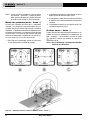
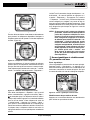
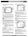
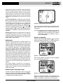
Common Display Elements
Figure 6 – Common Display Elements
The display screen in Sonde, Active Line Trace or Passive
Line Trace mode will show the following features:
Signal Angle Indicator – Angle toward the
field’s center graphically displayed; numeric value dis-
played below the graphic.
Battery Level – Indicates level of battery power.
Measured Depth/Distance – Displays the mea-
sured depth when receiver is touching the ground directly
over signal source. Displays computed distance when
the antenna mast is pointed at signal source in some
other manner. Displays feet/inches (U.S.A. default) or
meters (European default).
NOTE! Measured Depth is a
computed
number which
may vary from the physical depth or distance
depending on field strength and distortion.
Frequency – Shows current frequency setting in hertz or
kilohertz.
Mode – Icon for Sonde , Line Trace , or Passive
Line Trace mode.
+ Crosshair (Map Center) – shows your position rela-
tive to the target center.
Active View Area – The area within the circle in the cen-
ter of the operating screen, in which Sonde and Pole
icons, Tracing and Distortion lines appear.
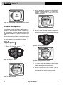
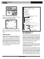
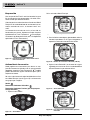
Display Elements: Sonde Mode
Figure 7 – Display Elements: Sonde Mode
Signal Strength – Strength of signal as sensed by
the lower Omnidirectional antenna.
| | Pipe Direction – Represents the approximate di-
rection of the pipe in which the sonde is lying.
Sonde Icon – Appears when approaching the loca-
tion of a Sonde.
Equator – Represents the mid-line of the
Sonde’s field perpendicular to the axis of the Poles.
(See on page 14.)
Pole Icon – Represents the location of either of the
two Poles of the Sonde’s dipole field.
(See on page 12.)
Display Elements: Active Line Trace Mode
Figure 8 – Display Elements (Line Trace Mode)
In Active Line Trace Mode the following features will
also be displayed:
Proximity Signal – A numerical indication showing
how close the signal source is to the locator. Displays
from 1 to 999 (Line Trace modes only).
Signal Strength – Strength of signal as sensed by
the lower Omnidirectional antenna.
Distortion Line (Upper Antenna Signal) – shows
the apparent direction of the field as detected at the
upper antenna. If out of alignment with the Tracing line,
indicates a distorted field.
Signal Angle
Indicator
Active
View Area
Crosshair
(Map
Center)
Measured
Depth/Distance
Battery
Level
Numeric
Horizontal
Angle
Indicator
Mode
Frequency
,
Pole Icon
Pipe
Direction
Sonde Icon
Equator
Signal Angle
Indicator
Proximity
Signal
Signal
Strength
Distortion
Line
(Dashed)
Tracing Line
(Solid)

Ridge Tool Company
9
NaviTrack
®
II
Tracing line (Lower Antenna Signal) – shows the
apparent direction of the field as detected at the lower
antenna.
Display Elements: Passive Trace Mode
The screen elements in Passive Trace Mode are the
same as those seen in Active Line Trace mode.
NOTE! Mode is determined by the type of target source
(Sonde or Line). For example, selecting the
512 Hz frequency from the Sonde mode section
of the frequency menu puts the SR-20 into
Sonde mode. (A frequency must be selected
from the correct category if it appears in more
than one category, such as 33 kHz).
Default Frequencies
The Master Frequency Menu contains a large set of fre-
quencies, but only some of these are made currently
available. They are made “Currently Available” by check-
ing them in the Master Frequency Menu,
as described on
page 23
. The frequencies which are currently available ap-
pear on the Main Menu when the Menu Key is pressed.
“Currently Available” frequencies can be checked in the
Main Menu, in which case they will appear when using the
Frequency Key. If they are unchecked in the Main Menu,
they will not appear when using the Frequency Key to
cycle through frequencies. Frequencies which appear in
the Main Menu and are checked for activation are called
“Checked-Active”.
Frequencies that are “Checked-Active” can be cycled
through simply by pressing the Frequency Key
(See Fi-
gure 9)
. A frequency chosen by pressing the Frequency
Key becomes the “In Use” frequency.
Currently available frequencies in default setting include:
Sonde Mode
• 512 Hz
Active Line Trace Mode
• 128 Hz
• 33 kHz
• 1 kHz
• 8 kHz
• 262 kHz
Passive Line Trace Mode
• 60 Hz (Power)
The use of these features is described in the Sonde
Locating, Active Line Tracing, and Passive Line Tracing
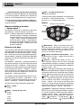
sections.
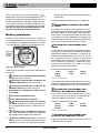
Keypad
Figure 9 – Keypad
Power ON/OFF – Powers NaviTrack II ON. Powers
the NaviTrack II down after a 3-second countdown. The
countdown can be interrupted before shutdown by press-
ing any key.
Up and Down Arrows – Used for locating choices
during menu selection; used for setting the Volume
Control when the Sound Key has been pressed.
Select Key – Used to make a choice during Menu
selection; in normal operation, used to force a Measured
Depth reading and re-center audio tone. Can be used to
force a depth display. Sets volume level in Sound menu.
Menu Key – Used to display a “tree” of choices in-
cluding frequency selections, display element choices,
brightness and contrast, and restoring default settings.
Within a menu, press to move up one level.
Volume Key – Used to raise or lower the volume
setting; will cycle the volume from current setting by
steps, increasing to maximum and then off. Pressing the
volume key opens the volume control panel if it is closed,
and closes it if it is open. Volume can also be raised and
lowered using the Up and Down Keys when in the
Volume control panel.
Frequency Key – Used to set the “In-Use” frequency
of the NaviTrack II from the set of checked-active fre-
quencies. The list of frequencies that have been set to
Checked-Active status can be modified via the Menu
Key. Frequencies are grouped into three sets: Sonde
Frequencies ( ), Line Trace Frequencies ( ) and
Power Frequencies ( ). Each press of the Frequency
Key cycles to the next Checked-Active frequency.
Light Sensor – Detects light levels and controls the
LCD backlight, which is set to come on under fairly
dark conditions. The backlight can be forced on by cov-
ering the sensor with your thumb.
Volume Control
Key
Down Key
Menu Navigation
Menu
Key
Select Key
Menu Item Select
Up Key Menu Navigation
Frequency Key
Light
Sensor
Power
ON/OFF
Key

Operation Time
Using alkaline cells, typical operation time is from about 12
to 24 hours depending on sound volume and how often
the backlight is on. Other factors that affect the operation
time will include chemistry of the battery (many of the new
high performance batteries, such as the “Duracell
®
ULTRA”
last 10% - 20% longer than conventional alkaline cells
under high demand applications). Operation at lower tem-
peratures will also reduce battery life.
The NaviTrack II display can also show random symbols
when the battery power is too low to drive the internal
logic circuits correctly. This is remedied by simply putting
fresh batteries into the unit.
To preserve battery life the NaviTrack II will automatically
shut down after one hour of no key presses. Simply turn
the unit on to resume use.
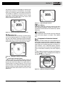
Low Battery Warning
When the battery gets low, a battery icon will appear
in the map area on the screen. This indicates that the bat-
teries need to be changed and that the unit will soon
shut down.
Figure 10 – Display Low-Battery Warning
Just before complete shut down, there will be a non-in-
terruptible power down sequence.
NOTE! Voltage on rechargeable batteries may some-
times drop so quickly that the unit will just shut
down. The unit will turn off and restart. Just re-
place the batteries and turn the unit back ON.
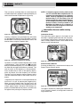
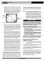
Starting Up
After pressing the Power Key on the keypad, the
RIDGID
®
logo displays, and the software version number
will appear on the left of the screen.
Ridge Tool Company
10
Figure 11 – Start-up Screen
In the European version, the screen will include a “CE”
logo:
Figure 12 – European Start-up Screen
Make a note of the software version in the box on
page 1
.
If technical support from Ridge is needed it will be helpful
to have it available.
Set Up
Once the NaviTrack II is up and running, the next step is
to set up the frequencies that match the Sonde, trans-
mitter, or line to be located.
Each frequency is selected for use by choosing it from a
list in the Main Menu. If the box on the Main Menu for that
frequency is checked, the frequency is in Checked-Active
status.
Checked-Active frequencies are already selected for
use and appear in sequence by pressing the Frequency
Key . (For example, the Sonde frequency of 512 kHz
is available by pressing the Frequency Key.)
Figure 13 – Sonde Frequency Selected With Frequency
Key
NaviTrack
®
II

Ridge Tool Company
11
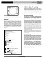
Activating Frequencies
Frequencies can be chosen for the set of Checked-Active
frequencies so they will be available using the Frequency
Key . Frequencies can also be deactivated to keep the
frequency set smaller.
Each frequency is activated by choosing it from a list in the
Main Menu
(See Figure 15)
. Frequencies are grouped by
category:
Sonde
Active Line Trace
Passive Line Trace (Power)
1. Push the Menu Key:
Figure 14 – Menu Key
The Main Menu is then activated:
Figure 15 – Main Menu
2. Using the up and down arrows, highlight the fre-
quency desired. In
Figure 16
, below, the operator is
activating a 128 Hz frequency.
Figure 16 – Highlighting a Desired Frequency (128 Hz)
3. Press the Select Key
(shown below)
to check the box
for each frequency intended for use.
Figure 17 – Select Key
Figure 18 – Desired Frequency Checked
4. Frequencies that have been selected for use will
show a check in the box next to them. These are
“Checked-Active” frequencies.
5. Press the Menu Key again to accept the choices
and exit. The last selected Checked-Active frequency
will now be the “In-Use” frequency.
Figure 19 – Menu Key
The Main Menu lists all frequencies currently available for
activation. For information on adding additional frequen-
cies to the Main Menu so they can be chosen for activa-
tion,
see “Frequencies Selection Control” on page 23.
(European versions of the NaviTrack II include a 93 kHz
Line Tracing frequency.
See the note on page 17
on
using this frequency.)
NaviTrack
®
II

Ridge Tool Company
12
Sounds of the NaviTrack II
The sound level is driven by the proximity to the target.
The closer to the target, the higher the sound pitch will be.
A rising tone indicates increasing signal.
In Sonde Mode, if the sound level reaches its highest
point, it will “re-scale” to a medium level and continue sig-
naling from the new starting point.
In Sonde Mode the pitch will “ratchet” upward. That is, it
will rise and fall in pitch while approaching the Sonde.
Moving away from the Sonde, it will drop to a lower pitch
and remain there as long as one moves away from the
Sonde. Moving back toward the Sonde again it will re-
sume rising and falling starting from the level it had
reached previously. This serves as a guide to when you
are getting closer or further away from the Sonde.
In Line Trace or Passive Line Trace mode, sound is on
one continuous curve and does not re-scale.
If desired, force the sound to re-center at a medium
level (in any mode) by pressing the Select Key during
operation.
Sonde Locating
The NaviTrack II can be used to locate the signal of a
Sonde (transmitter) in a pipe, so that its location can be
identified above ground. Sondes can be placed at a
problem point in the pipe using a camera push rod or
cable. They can also be flushed down the pipe. A Sonde
is often used for locating non-conductive pipe and conduit.
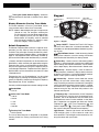
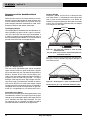
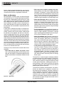
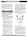
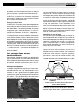
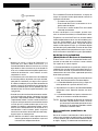
The field of a Sonde is different in form than the circular
field around a long conductor such as a pipe or cable. It is
more like the field around the Earth, with a North Pole and
a South Pole.
NaviTrack
®
II
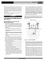
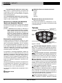
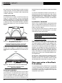
Figure 20 – Earth's Dipole Field
In the Sonde’s field, the NaviTrack II will detect the points
at either end where the field lines curve down toward
the vertical, and it will mark these points on the map dis-
play with a “pole” icon ( ). The NaviTrack II will also
show a line at 90 degrees to the Sonde, centered between
the Poles, known as the “equator”, much like the Equator
on a map of the Earth if the planet were viewed sideways.
Note that because of the NaviTrack’s Omnidirectional
antennas, the signal stays stable regardless of orientation.
This means the signal will increase smoothly approaching
the Sonde, and decrease smoothly moving away.
Figure 21 – Earth's Dipole Field Sideways
When locating a Sonde set up the locate in the fol-
lowing manner:
Activate the Sonde before putting it in the line. Select the
same frequency on the NaviTrack II and make sure it is
receiving the signal.
After the Sonde has been sent into the pipe, go to the
suspected Sonde location. If the direction of the pipe is
unknown, push the Sonde a shorter distance into the line
(~15 feet from the access is a good starting point).
Pole
Pole
Equator
Ground
IMPORTANT! Signal strength is the key factor in
determining the Sonde’s location. To
ensure an accurate locate take care
to maximize the Signal Strength prior
to marking an area for excavation.
The following assumes that the Sonde is in a hori-
zontal pipe, the ground is approximately level and the
NaviTrack II is held with the antenna mast vertical.
N
S

Ridge Tool Company
13
NaviTrack
®
II
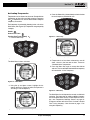
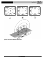
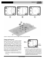
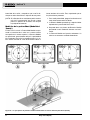
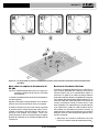
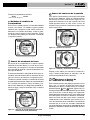
Location Methods
There are three major parts to locating a Sonde. The
first step is to localize the sonde. The second part is
pinpointing. The third is verifying its location.
Step 1: Localize the sonde
• Hold the NaviTrack II so the antenna mast is pointing
outward. Sweep the antenna mast in the suspected di-
rection of the Sonde while observing the Signal
Strength and listening to the sound. The signal will be
highest when the antenna mast is pointing in the di-
rection of the Sonde.
• Lower NaviTrack II to its normal operating position
(antenna mast vertical) and walk in the direction of the
Sonde. Approaching the Sonde, the Signal Strength will
increase and the audio tone will rise in pitch. Use the
Signal Strength and the sound to maximize the signal.
• Maximize the Signal Strength. When it appears to be
at its highest point, place the NaviTrack II close to the
ground over the high-signal point. Be careful to hold the
receiver at a constant height above the ground, as dis-
tance affects Signal Strength.
• Note the Signal Strength and move away from the high
point in all directions. Move the NaviTrack II far enough
in all directions to verify that the Signal Strength drops
significantly on all sides. Mark the point of highest
Signal Strength with a yellow Sonde Marker (clipped to
antenna mast for convenience). This is the suspected
Sonde location.
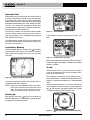
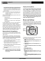
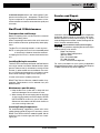
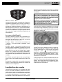
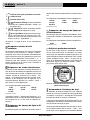
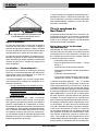
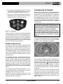
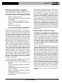
Figure 22 – Poles and Equator of a Sonde
If while “getting closer” the Equator appears on the screen
follow it in the direction of an increasing Signal Strength to
localize the Sonde.
If a Pole appears before the Equator appears, localize the
Sonde by centering the Pole in the cross-hairs.
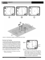
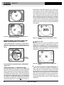
Step 2: Pinpoint the Sonde
The Poles should appear on either side of the max-
imum signal point, an equal distance on either side if the
Sonde is level. If they are not visible on the screen at the
point of maximum Signal Strength, move from the max-
imum point perpendicular to the dotted line (Equator)
until one appears. Center the locator over the Pole.
Where the Poles occur depends on the Sonde’s depth.
The deeper the Sonde, the further away from it the Poles
will be.
The dotted line represents the Equator of the Sonde. If the
Sonde is not tilted, the Equator will intersect the Sonde at
maximum Signal Strength and minimum Measured Depth.
NOTE! Being on the Equator does not mean that the
locator is over the Sonde. Always verify the
locate by maximizing Signal Strength and
marking both Poles.
• Mark the first Pole location found with a red triangular
Pole marker. After centering on the Pole, a double-line
indicator will appear. This line represents how the
Sonde is lying underground, and in most cases also
represents the pipe’s approximate direction.
• When the locator gets close to a Pole, a zoom ring will
appear centered on the Pole, allowing precision cen-
tering.
• The second Pole will be a similar distance from the
Sonde location in the opposite direction. Locate it in the
same manner and mark it with a red triangular marker.
• If the Sonde is level, the three markers should be
aligned and the red Pole markers should be similar dis-
tances from the yellow Sonde marker. If they are not,
a tilted Sonde may be indicated.
(See “Tilted Sonde”
on page 14)
. It is generally true that the Sonde will be
on the line between the two Poles, unless there is
extreme distortion present.
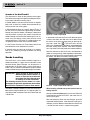
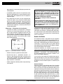
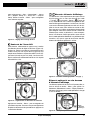
Step 3: Verify the locate
• It is important to verify the Sonde’s location by cross-
checking the receiver’s information and maximizing
Signal Strength. Move the NaviTrack II away from
the maximum Signal Strength, to make sure that the
signal drops off on all sides. Make sure to move the
unit far enough to see a significant signal drop in each
direction.

Figure 23 – Sonde Locate: Equator
• Double-check the two Pole locations.
• Notice that the Measured Depth reading at the maxi-
mum Signal Strength location is reasonable and con-
sistent. If it seems far too deep or too shallow, recheck
that there is an actual maximum Signal Strength at that
location.
• Notice that the poles and the point of highest Signal
Strength lie on a straight line.
It doesn’t matter whether you locate the Poles first, and
then the Equator, or the Equator first, and then the Poles,
or one Pole, then the Equator, and then the other Pole.
You can even locate the Sonde using just the Signal
Strength, and then verify your result with the Poles and
Equator. What is important is that you verify all the data
points, and mark the Sonde’s position where the signal is
highest.
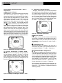
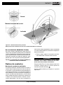
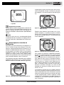
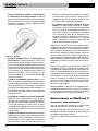
Tilted Sondes
If the Sonde is tilted, one Pole will move closer to the
Sonde and the other farther away so that the Sonde lo-
cation no longer lies midway between the two Poles. The
Signal Strength of the nearer Pole becomes much
higher than that of the more distant Pole if the Sonde is
vertical (as it could be if it fell into a break in the line);
however, it can still be located.
If the Sonde is
vertical
what is seen on the screen is a
single Pole at the point of maximum Signal Strength.
(The RIDGID Floating Sonde is designed to have a
Ridge Tool Company
14
NaviTrack
®
II
single Pole “visible” and is weighted to maintain the
Sonde on a vertical axis.
See Note below
.)
It is important to realize that a severely tilted Sonde
can cause the Pole locations and the Equator to appear
offset because of the angle of the Sonde; but maximiz-
ing the Signal Strength will still guide to the best location
for the Sonde.
Floating Sondes
Some Sondes are designed to be flushed or to drift down
a pipe pushed by water flow. Because these Sondes
swing much more freely than a torpedo-shaped Sonde in
a pipe, they can be oriented any which way. This means
the Equator may be distorted by tilting, and the location of
the Poles may vary. The only guarantee of having located
a floating Sonde is maximizing the Signal Strength and
double-checking that the signal falls away on every side
of the maximum signal location.
NOTE! If a Sonde is moving, it may be easier to “chase”
a pole and then pinpoint the actual position of
the Sonde after the Sonde has stopped moving.
Measuring Depth (Sonde Mode)
The NaviTrack II calculates Measured Depth by com-
paring the strength of the signal at the lower antenna to
the upper antenna. Measured Depth is approximate; it will
usually reflect the physical depth when the mast is held
vertical and the bottom antenna is touching the ground di-
rectly above the signal source,
assuming no distortion is
present.
1. To measure depth, place the locator on the ground,
directly above the Sonde.
2. Measured Depth will be shown in the lower left hand
corner of the NaviTrack II’s display screen.
3. A Measured Depth reading can be forced by pressing
the Select Key during a locate.
4. Measured Depth will be accurate only if the signal is
undistorted.
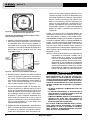
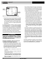
Clipping (Sonde Mode)
Occasionally the Signal Strength will be strong enough
that the receiver will be unable to process the entire sig-
nal, a condition known as “clipping”. When this occurs a
warning symbol will appear on the screen. It means
that the signal is particularly strong.
NOTE! Measured Depth Display is disabled under
clipping conditions.
IMPORTANT! Remember that being on the Equator
does not mean one is over the Sonde.
Seeing two Poles aligned on the dis-
play is not a substitute for centering
over each Pole separately and mark-
ing their locations as described
above.
If the Poles are not visible, extend the search.
For best accuracy use the bubble level. The mast
MUST be vertical when marking the Poles and
Equator, or their locations will be less accurate!

Ridge Tool Company
15
NaviTrack
®
II
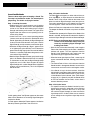
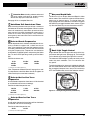
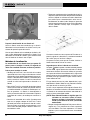
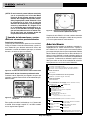
Figure 24 – Screen Display in Different Locations (Sonde)
On the 1" Pole On the Equator Approaching the 2nd Pole

Ridge Tool Company
16
Line Tracing
Active Line Tracing
In active line tracing, underground lines are energized
with a line transmitter. This active signal is then traced
using the NaviTrack II. A line transmitter is different
from a Sonde in that it is used for tracing an energized
line, rather than acting as a target for a locate the way a
Sonde does. Line transmitters energize lines by direct
connection with clips, by directly inducing a signal using
a clamp, or by inducing the signal using inductive coils
built in to the transmitter.
1. Energize the line according to the manufacturer’s
instructions. Select the transmitter frequency.
DANGER
Connect both ends of the transmitter leads before
turning the transmitter on, to avoid electric shock.
Set the frequency used on the NaviTrack II to the same
frequency used on the transmitter. Be sure it has a line
trace icon.
Push the Menu button to return to the operating screen.
Figure 26 – Line Trace Frequency Chosen with the
Frequency Key
(This screen will flash briefly when a new frequency is
chosen)
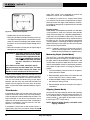
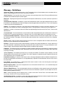
2. Observe the Proximity Signal and Signal Strength to
ensure the NaviTrack II is picking up the transmitted
NaviTrack
®
II
Normal
Tilted
Maximum Signal Strength
Figure 25 – Tilted Sonde, Poles and Equator
Note the Pole on the right is closer to the Equator, due to tilt.

Ridge Tool Company
17
signal.
(See Figure 27 below)
. The signal should
peak over the line and drop off on either side. The
Signal Angle indicator will be near zero when the
NaviTrack II is directly above the line.
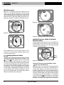
Figure 27 – High Probability Locate
3. When tracing, the direction the pipe or cable is run-
ning will be shown on the screen with 2 lines, one
solid and one dashed. The solid line (the Tracing
line) is the signal as seen by the lower antenna node
and the dashed line (the Distortion Line) is the signal
as seen by the upper one.
(See Figure 27.)
4. The Tracing line has three important functions. It
represents the location, and the direction, of the sig-
nal being traced. It reflects changes in direction of the
target utility — when the utility makes a turn, for ex-
ample. And it helps recognize signal distortion, when
compared to the dashed line — if something is inter-
fering with the signal and distorting its shape, the
dashed line could be significantly offset or skewed.
5. Use the Proximity Number, Signal Strength, and
Tracing and Distortion lines to guide the line trace.
These three pieces of information are generated
from discrete signal characteristics to help the oper-
ator discern the quality of the locate. An undistorted
signal emitted from a line is strongest directly over that
line. By maximizing the Proximity Signal, and cen-
tering the Tracing and Distortion lines on the screen
the confidence in a “good” locate is high. Confirm a lo-
cate by testing whether the Measured Depth reading
is stable and reasonable.
Testing for the consistency of the Measured Depth read-
ing can be done by raising the NaviTrack II a known dis-
tance (say, 12" exactly) and observing whether the
Measured Depth indicator increases by the same amount.
Small variation is acceptable, but if the Measured Depth
does not change, or changes drastically, it is an indication
of a “distorted” field, or a very low level signal on the
line. As always, the only way to be completely certain of
the location of a utility is through visual inspection by ex-
posing the utility.
NOTE! The accuracy of position and Measured Depth
measurements improves as the NaviTrack’s low-
er antenna node is placed closer and closer to
the target utility. Rechecking the Measured Depth
and position periodically during the excavation
process can help avoid damage to a target utility
and may identify additional utility signals that
were not noticed prior to excavation.
WARNING
Care should be taken to watch for signal interfer-
ence that may give inaccurate readings. The
Tracing line is only representative of the position of
the buried utility if the field is UNDISTORTED. Do
NOT base your locate solely on the Tracing Line.
Always cross check your locate by ensuring that:
• The Tracing Line and the Distortion Line are
substantially aligned.
• The Proximity Signal and the Signal Strength
maximize when the Tracing Line crosses the
map center.
• The Measured Depth increases appropriately as
you raise the unit vertically and the Tracing Line
and the Distortion Line remain aligned.
Measured Depth readings should be taken as esti-
mates and actual depths should be independently
verified by potholing or other means prior to digging.
Note on 93 kHz Frequency Use
NOTE! European versions of the NaviTrack II offer an
additional 93 kHz frequency for Line Tracing.
The default 93 kHz frequency has an actual cycle count
of 93,696 cycles per second.
Some older transmitters use a different value for the
nominal 93 kHz frequency, 93,622.9 cycles per sec-
ond.
If you find that your transmitter signal at 93 kHz cannot
be detected by the NaviTrack II, set the locator’s fre-
quency to 93-B kHz, which is set to the older value. Both
93 and 93-B frequencies can be found under the Line
Trace category of the Frequency Selection sub-menu.
NaviTrack
®
II
Distortion
Line (Dashed)
Trace
Line
(Solid)

Ridge Tool Company
18
Passive Line Tracing
In passive mode the NaviTrack II senses fields gener-
ated by wires carrying alternating current (AC), without
a transmitter being attached. Buried power lines typically
do not emit any traceable signal unless power is flowing
in the wires. For example streetlights that are turned off
can be hard to trace passively. Due to coupling (either
through induction or through capacitance), all metallic
lines in an area can be energized passively. Because of
this, it is possible to locate lines passively but it can be
difficult to identify which line the operator is tracing.
1. Select a Passive AC Trace Frequency with the pas-
sive line trace icon.
Figure 29 – 60 Hz Passive Trace Frequency
2. The NaviTrack II has two passive AC tracing fre-
quency settings. They are 50 Hz, and 60Hz. The
50Hz and 60Hz frequencies are set to respond to
the 9th harmonic of the commonly used AC frequen-
cies. U.S. installations are typically 60 Hz, while
European installations are typically 50 Hz.
NaviTrack
®
II
Figure 28 – Screen Display in Different Locations (Active Line Tracing)
Trace Line
(Solid)
Distortion
Line
(Dashed)
La page est en cours de chargement...
La page est en cours de chargement...
La page est en cours de chargement...
La page est en cours de chargement...
La page est en cours de chargement...
La page est en cours de chargement...
La page est en cours de chargement...
La page est en cours de chargement...
La page est en cours de chargement...
La page est en cours de chargement...
La page est en cours de chargement...
La page est en cours de chargement...
La page est en cours de chargement...
La page est en cours de chargement...
La page est en cours de chargement...
La page est en cours de chargement...
La page est en cours de chargement...
La page est en cours de chargement...
La page est en cours de chargement...
La page est en cours de chargement...
La page est en cours de chargement...
La page est en cours de chargement...
La page est en cours de chargement...
La page est en cours de chargement...
La page est en cours de chargement...
La page est en cours de chargement...
La page est en cours de chargement...
La page est en cours de chargement...
La page est en cours de chargement...
La page est en cours de chargement...
La page est en cours de chargement...
La page est en cours de chargement...
La page est en cours de chargement...
La page est en cours de chargement...
La page est en cours de chargement...
La page est en cours de chargement...
La page est en cours de chargement...
La page est en cours de chargement...
La page est en cours de chargement...
La page est en cours de chargement...
La page est en cours de chargement...
La page est en cours de chargement...
La page est en cours de chargement...
La page est en cours de chargement...
La page est en cours de chargement...
La page est en cours de chargement...
La page est en cours de chargement...
La page est en cours de chargement...
La page est en cours de chargement...
La page est en cours de chargement...
La page est en cours de chargement...
La page est en cours de chargement...
La page est en cours de chargement...
La page est en cours de chargement...
La page est en cours de chargement...
La page est en cours de chargement...
La page est en cours de chargement...
La page est en cours de chargement...
La page est en cours de chargement...
La page est en cours de chargement...
La page est en cours de chargement...
La page est en cours de chargement...
La page est en cours de chargement...
La page est en cours de chargement...
La page est en cours de chargement...
La page est en cours de chargement...
La page est en cours de chargement...
La page est en cours de chargement...
La page est en cours de chargement...
La page est en cours de chargement...
La page est en cours de chargement...
La page est en cours de chargement...
La page est en cours de chargement...
La page est en cours de chargement...
La page est en cours de chargement...
La page est en cours de chargement...
La page est en cours de chargement...
La page est en cours de chargement...
La page est en cours de chargement...
La page est en cours de chargement...
La page est en cours de chargement...
La page est en cours de chargement...
La page est en cours de chargement...
-
 1
1
-
 2
2
-
 3
3
-
 4
4
-
 5
5
-
 6
6
-
 7
7
-
 8
8
-
 9
9
-
 10
10
-
 11
11
-
 12
12
-
 13
13
-
 14
14
-
 15
15
-
 16
16
-
 17
17
-
 18
18
-
 19
19
-
 20
20
-
 21
21
-
 22
22
-
 23
23
-
 24
24
-
 25
25
-
 26
26
-
 27
27
-
 28
28
-
 29
29
-
 30
30
-
 31
31
-
 32
32
-
 33
33
-
 34
34
-
 35
35
-
 36
36
-
 37
37
-
 38
38
-
 39
39
-
 40
40
-
 41
41
-
 42
42
-
 43
43
-
 44
44
-
 45
45
-
 46
46
-
 47
47
-
 48
48
-
 49
49
-
 50
50
-
 51
51
-
 52
52
-
 53
53
-
 54
54
-
 55
55
-
 56
56
-
 57
57
-
 58
58
-
 59
59
-
 60
60
-
 61
61
-
 62
62
-
 63
63
-
 64
64
-
 65
65
-
 66
66
-
 67
67
-
 68
68
-
 69
69
-
 70
70
-
 71
71
-
 72
72
-
 73
73
-
 74
74
-
 75
75
-
 76
76
-
 77
77
-
 78
78
-
 79
79
-
 80
80
-
 81
81
-
 82
82
-
 83
83
-
 84
84
-
 85
85
-
 86
86
-
 87
87
-
 88
88
-
 89
89
-
 90
90
-
 91
91
-
 92
92
-
 93
93
-
 94
94
-
 95
95
-
 96
96
-
 97
97
-
 98
98
-
 99
99
-
 100
100
-
 101
101
-
 102
102
-
 103
103


RIDGID Metal Detector Metal Detector Manuel utilisateur
- Taper
- Manuel utilisateur
- Ce manuel convient également à
dans d''autres langues
Documents connexes
Autres documents
-
Amprobe UAT-610 & UAT-620 Manuel utilisateur
-
Amprobe AT-5000 Underground Wire Tracer Manuel utilisateur
-
Greenlee BLL-200 Buried Line Locator Manuel utilisateur
-
koban KCL-01 Manuel utilisateur
-
C.Scope MXT4 Manuel utilisateur
-
Amprobe AT-6000 Manuel utilisateur
-
Radiodetection RD7100 Manuel utilisateur
-
Amprobe Kit localizador de cables avanzado AT-8030 de Amprobe Manuel utilisateur
-
SPX SuperCAT 4S Manuel utilisateur
-
Power Fist 8415002 Le manuel du propriétaire