Regency Fireplace Products Horizon HZI540PB Le manuel du propriétaire
- Catégorie
- Cheminées
- Taper
- Le manuel du propriétaire
Ce manuel convient également à

FPI FIREPLACE PRODUCTS INTERNATIONAL LTD. 6988 Venture St., Delta, BC Canada, V4G 1H4
919-295b
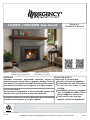
MODELS: L540PB-NG2 Natural Gas L540PB-LP2 Propane
HZI540PB-NG2 Natural Gas HZI540PB-LP2 Propane
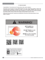
WARNING:
Improper installation, adjustment, alteration, service or
maintenance can cause injury or property damage. Refer to
this manual. For assistance or additional information consult
an authorized installer, service agency or the gas supplier.
FOR YOUR SAFETY
Do not store or use gasoline or other fl ammable vapours and
liquids in the vicinity of this or any other appliance.
Installation and service must be performed by an authorized
installer, service agency or the gas supplier.
FOR YOUR SAFETY
What to do if you smell gas:
Do not try to light any appliance
Do not touch any electrical switch:
do not use any phone in your
building.
Immediately call your gas supplier
from a neighbour's phone. Follow
the gas supplier's instructions.
If you cannot reach your gas
supplier, call the fi re department.
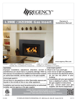
L540PB / HZI540PB Gas Insert
03.05.14
Owners &
Installation Manual
Tested by:
Installer: Please complete the details on the back cover
and leave this manual with the homeowner.
Homeowner: Please keep these instructions for future reference.
www.regency-fi re.com

2
L540PB-2 / HZI540PB-2 Direct Vent Gas Insert
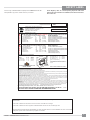
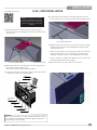
TO THE NEW OWNER
Congratulations! You are the owner of a state-of-the-art Gas Insert by Regency.
The Regency Gas Insert Series of hand crafted appliances has been designed to provide you with all the
warmth and charm of a fi replace, at the fl ick of a switch. The models L540PB / HZI540PB of this series have
been approved by Warnock Hersey for both safety and effi ciency. As it also bears our own mark, it promises
to provide you with economy, comfort and security for many trouble free years to follow.
Please take a moment now to acquaint yourself with these instructions and the many features of your
Regency Fireplace.

L540PB-2 / HZI540PB-2 Direct Vent Gas Insert
33
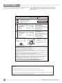
TABLE OF CONTENTS
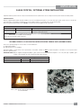
Optional PebbleS / GLASS crystal Installation for Fire-
box Base (AROUND BURNER) ..................................27
HZI540PB optional log set installation ........................29
L540PB log set installation .........................................31
Heat exchange return ..................................................34
Brick panel installation .................................................35
Enamel panel installation.............................................36
Glass door removal / installation .................................37
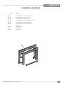
3 sided low profi le faceplate installation ......................38
Regular faceplate installation ......................................39
Optional Hearth Trim Installation .................................41
Optional screen installation .........................................42
OPERATING INSTRUCTIONS
Operating Instructions ................................................43
Lighting Procedure ......................................................43
Shutdown Procedure ...................................................43
First Fire ......................................................................43
Automatic Convection Fan Operation.........................43
Normal Operating Sounds Of Gas Appliances ............44
Copy Of Lighting Instruction Plate ...............................44
MAINTENANCE
Maintenance Instructions............................................45
Door Glass ..................................................................45
Pilot Adjustment ...........................................................46
General Vent Maintenance ..........................................46
Log Replacement ........................................................46
Glass Gasket ...............................................................46
Glass Burner Removal ................................................47
Glass Burner install .....................................................47
L540PB ceramic burner Removal / installation............48
Fan removal / installation.............................................49
Fan Installation ............................................................49
valve replacement .......................................................50
PARTS LIST
Main Assembly ............................................................51
Low profi le faceplate ...................................................53
WARRANTY
Warranty ......................................................................55
DIMENSIONS
Unit dimensions .............................................................4
SAFETY LABEL
Copy of the Safety Label ...............................................5
REQUIREMENTS
MA Code - CO Detector.................................................7
INSTALLATION
Important Message ......................................................8
Before You Start ............................................................8
Important Message ......................................................9
For Your Safety ..............................................................9
Specifi cations ................................................................9
Gas Pressure Testing ....................................................9
Installation Into A Solid Fuel Burning Fireplace Or
Factory Built Fireplace ...................................................9
Before You Start ............................................................9
Installation Checklist ....................................................10
Materials Required ......................................................10
Minimum Fireplace Dimensions .................................10
Minimum Clearances to combustibles .........................11
Gas Connection ...........................................................12
Venting.........................................................................12
Flue / vent installation ..................................................13
Leveling leg adjustment ...............................................14
Air shutter Adjustment .................................................15
High Elevation .............................................................16
Gas Line Installation ....................................................16
Gas Pipe Pressure Testing ..........................................16
820 S.I.T. Valve Description .........................................16
Conversion from NG to LP ........................................17
GT remote control installation ......................................19
GTM remote control installation...................................20
GTMF remote control installation ................................22
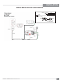
Wiring Diagrams ..........................................................24
Wiring diagram for Gtmf remote ..................................25
Optional Wall Thermostat ...........................................26
Optional Remote Control .............................................26
Optional Wall Switch ....................................................26
Glass crystal / optional stone installation.....................27

4
L540PB-2 / HZI540PB-2 Direct Vent Gas Insert
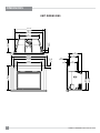
DIMENSIONS
UNIT DIMENSIONS
45-1/2"
30-1/4"
39-13/16"
31-3/8"
2-1/4"
26"
36"
3-1/2"
17-1/4"
38-11/16"
17"
10"
1"
1-1/4"
23-5/8"
23-9/16"
12-1/4"
(982mm)
(914mm)
(660mm)
(1156mm)
(1010mm)
(795mm)
(438mm)
(89mm)
(768mm)
(598mm)
(600mm)
(32mm)
(25mm)
(254mm)
(308mm)
(432mm)
(57mm)

L540PB-2 / HZI540PB-2 Direct Vent Gas Insert
5
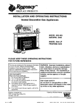
SAFETY LABEL
This is a copy of the labels that accompany each L540PB Gas Insert. We
have printed a copy of the contents here for your review.
NOTE: Regency units are constantly being improved. Check the
label on the unit and if there is a difference, the label on the unit is
the correct one.
NATURAL GAS FIREPLACE INSERT:
Factory Equipped For Altitude 0-4500ft. (0-1370m)
Min. supply pressure 5“ WC (1.25 kpa)
Low Setting Man. pressure 1.6" WC (0.41 kpa)
Max. Manifold pressure 3.5" WC (0.87 kpa)
Orifice size #32 DMS
Minimum input 25,000 Btu/h (7.33 kW)
Maximum input 38,000 Btu/h (11.14 kW)
Min. supply pressure 11" WC (2.73 kpa)
Low Setting Man. pressure 6.4" WC (1.59 kpa)
Max. Manifold pressure 10" WC (2.48 kpa)
Orifice size #51 DMS
Minimum input 30,000 Btu/h (8.79 kW)
Maximum input 38,000 Btu/h (11.14 kW)
PROPANE GAS FIREPLACE INSERT:
Factory Equipped For Altitude 0-4500ft. (0-1370m)
MODEL L540PB-NG2
MODEL L540PB-LP2
Model/Modele:
L540PB-NG2
919-296a
DO NOT REMOVE THIS LABEL /
NE PAS ENLEVER CETTE ETIQUETTE
Serial No. / No de serie
427
427
Duplicate Serial number
Listed: VENTED GAS FIREPLACE HEATER
/
Certified for/Certifi e pour: CANADA and U.S.A.
Tested to
Conforms to
Certified to:
: CAN/CGA-2.17-M91(R2009)
: ANSI Z21.88-2009
CSA 2.33-2009
FOYER AU GAZ À ÉVACUATION
é
VENTED GAS FIREPLACE HEATER - NOT FOR USE WITH SOLID FUELS. /
NE PAS UTILISER AVEC DUCOMBUSTIBLE SOLIDE.
FOYER AU
GAZ À ÉVACUATION -
Model/Modele:
-LP2
L540PB
ÉÉQUIP A L'UISINE POUR GAZ PROPANE
MODEL L540PB-LP2
ÉÉQUIP A L'UISINE POUR GAZ NATURAL
MODEL L540PB-NG2
Pression d'allimentation minimum
Pression la tubulure d' chappement basse
Pression la tubulure d' chappement lev e
Dimensions de l'orifice
D bit Calorifique minimum
D bit Calorifique maximum
à
à
é
ééé
é
é
Pression d'allimentation minimum
Pression la tubulure d' chappement basse
Pression la tubulure d' chappement lev e
Dimensions de l'orifice
D bit Calorifique minimum
D bit Calorifique maximum
à
à
é
ééé
é
é
Mantel Clearances
FPI Fireplace Products International Ltd.,
Delta BC, CANADA
MADE IN CANADA /FABRIQUE AU CANADA
Minimum Clearances to Combustibles
from Insert
This appliance must be installed in accordance with local codes, if any; if none, follow the National Fuel Gas Code, ANSI Z223.1, or Natural Gas and
Propane Installation Code, CSA B149.1.
This appliance is only for use with the type of gas indicated on the rating plate.
This appliance is not convertible for use with other gases unless a certified kit is used.
This appliance is only for use with the type of gas indicated on the rating plate and may be installed in an aftermarket, permanently located, manufactured
(mobile) home where not prohibited by local codes. See owner's manual for details
WARNING. This fireplace has been converted for use with a gas fireplace insert only and cannot be used for burning wood or solid fuels unless all original
parts have been replaced, and the fireplace re-approved by the authority having jurisdiction.
Installer l'appareil selon les codes ou règlements locaux, ou, en l'absence de tels règlements, selon les codes d'installation ANSI Z223.1, National Fuel
Gas Code ou CSA-B149.1 en vigueur.
AVERTISSEMENT : Ce foyer a été converti pour utilisation avec un foyer au gaz encastrable et ne peut être utiliser pour brûler du bois ou d'autres
combustibles solides à moins que toutes les pièces d'origine aient été remplacées et que le foyer ait été approuvé de nouveau par l'autorité compétente.
This vented gas fireplace heater is not for use with air filters. Ne pas utiliser de filtre à air avec ce foyer au gaz à évacuation.
Cet appareil doit être utilize uniquement avec le type de gaz indiqué sur la plaque signalétique. Cet appareil peut être installé dans une maison
préfabriquée ou mobile (É.-U. seulement) installée à demeure si les règlements locaux le permettent. Voir la notice de l'utilisateur pour plus de
renseignements. Cet appareil ne peut pas être utilisé avec d'autres gaz sauf si une trousse de conversion certifiée est fournie.
Cet appareil n'est pas convertible pour une utilisation avec d'autres gaz, sauf si un kit certifié est utilisé.
Cet appareil doit être utilize uniquement avec le type de gaz indiqué sur la plaque signalétique. Cet appareil peut être installé dans une maison
préfabriquée ou mobile (É.-U. seulement) installée à demeure si les règlements locaux le permettent. Voir la notice de l'utilisateur pour plus de
renseignements.
Electrical supply / Électrique 115VAC, 2.5 A, 60Hz, Less than 10A Fan Part # 911-071
A
C
B
E
K
D
L
G
Side wall A 12” (305mm)
Ceiling B 60” (1524mm)
12" Mantel Max. C 24” (610mm)
Min. Alcove Width K 56" (1422mm)
Max. Alcove Depth L 36” (914mm)
*Min. Hearth Width D 14” (356mm)
*Min. Hearth Length E 44” (1016mm)
Max. Mantle Depth G 12" (305mm)
* See installation manual for hearth requirements.
*If unit is raised 6" from the floor - no hearth
required.
@ 24" form fireplace opening
4001172
For the State of Massachusetts, installation and repair must be done by a plumber or gasfi tter licensed in the Commonwealth of
Massachusetts.
For the State of Massachusetts, fl exible connectors shall not exceed 36 inches in length.
For the State of Massachusetts, the appliances individual manual shut-off must be a t-handle type valve.
The State of Massachusetts requires the installation of a carbon monoxide alarm in accordance with NFPA 720 and a CO alarm with
battery back up in the same room where the gas appliance is installed.

6
L540PB-2 / HZI540PB-2 Direct Vent Gas Insert
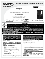
SAFETY LABEL
This is a copy of the labels that accompany each HZI540PB Gas Insert.
We have printed a copy of the contents here for your review.
NOTE: Regency units are constantly being improved. Check the
label on the unit and if there is a difference, the label on the unit is
the correct one.
For the State of Massachusetts, installation and repair must be done by a plumber or gasfi tter licensed in the Commonwealth of
Massachusetts.
For the State of Massachusetts, fl exible connectors shall not exceed 36 inches in length.
For the State of Massachusetts, the appliances individual manual shut-off must be a t-handle type valve.
The State of Massachusetts requires the installation of a carbon monoxide alarm in accordance with NFPA 720 and a CO alarm with
battery back up in the same room where the gas appliance is installed.
NATURAL GAS FIREPLACE INSERT:
Factory Equipped For Altitude 0-4500ft. (0-1370m)
Min. supply pressure 5“ WC (1.25 kpa)
Low Setting Man. pressure 1.6" WC (0.41 kpa)
Max. Manifold pressure 3.5" WC (0.87 kpa)
Orifice size #32 DMS
Minimum input 25,000 Btu/h (7.33 kW)
Maximum input 38,000 Btu/h (11.14 kW)
Min. supply pressure 11" WC (2.73 kpa)
Low Setting Man. pressure 6.4" WC (1.59 kpa)
Max. Manifold pressure 10" WC (2.48 kpa)
Orifice size #51 DMS
Minimum input 30,000 Btu/h (8.79 kW)
Maximum input 38,000 Btu/h (11.14 kW)
PROPANE GAS FIREPLACE INSERT:
Factory Equipped For Altitude 0-4500ft. (0-1370m)
MODEL -NG2HZI540PB
HZI540PBMODEL -LP2
Model/Modele:
-NG2
HZI540PB
919-297a
DO NOT REMOVE THIS LABEL /
NE PAS ENLEVER CETTE ETIQUETTE
Serial No. / No de serie
428
428
Duplicate Serial number
Listed:
Certified for/Certifi e pour: CANADA and U.S.A.
VENTED GAS FIREPLACE HEATER
/
Tested to
Conforms to
Certified to:
: CAN/CGA-2.17-M91(R2009)
: ANSI Z21.88-2009
CSA 2.33-2009
FOYER AU GAZ À ÉVACUATION
é
VENTED GAS FIREPLACE HEATER - NOT FOR USE WITH SOLID FUELS. /
NE PAS UTILISER AVEC DUCOMBUSTIBLE SOLIDE.
FOYER AU
GAZ À ÉVACUATION -
Model/Modele:
-LP2
HZI540PB
ÉÉQUIP A L'UISINE POUR GAZ PROPANE
MODEL HZI540PB-LP2
ÉÉQUIP A L'UISINE POUR GAZ NATURAL
MODEL HZI540PB-NG2
Pression d'allimentation minimum
Pression la tubulure d' chappement basse
Pression la tubulure d' chappement lev e
Dimensions de l'orifice
D bit Calorifique minimum
D bit Calorifique maximum
à
à
é
ééé
é
é
Pression d'allimentation minimum
Pression la tubulure d' chappement basse
Pression la tubulure d' chappement lev e
Dimensions de l'orifice
D bit Calorifique minimum
D bit Calorifique maximum
à
à
é
ééé
é
é
Mantel Clearances
FPI Fireplace Products International Ltd.,
Delta BC, CANADA
MADE IN CANADA /FABRIQUE AU CANADA
Minimum Clearances to Combustibles
from Insert
This appliance must be installed in accordance with local codes, if any; if none, follow the National Fuel Gas Code, ANSI Z223.1, or Natural Gas and
Propane Installation Code, CSA B149.1.
This appliance is only for use with the type of gas indicated on the rating plate.
This appliance is not convertible for use with other gases unless a certified kit is used.
This appliance is only for use with the type of gas indicated on the rating plate and may be installed in an aftermarket, permanently located, manufactured
(mobile) home where not prohibited by local codes. See owner's manual for details
WARNING. This fireplace has been converted for use with a gas fireplace insert only and cannot be used for burning wood or solid fuels unless all original
parts have been replaced, and the fireplace re-approved by the authority having jurisdiction.
Installer l'appareil selon les codes ou règlements locaux, ou, en l'absence de tels règlements, selon les codes d'installation ANSI Z223.1, National Fuel
Gas Code ou CSA-B149.1 en vigueur.
AVERTISSEMENT : Ce foyer a été converti pour utilisation avec un foyer au gaz encastrable et ne peut être utiliser pour brûler du bois ou d'autres
combustibles solides à moins que toutes les pièces d'origine aient été remplacées etque le foyer ait été approuvé de nouveau par l'autoritécompétente.
This vented gas fireplace heater is not for use withair filters. Ne pas utiliser de filtre à air avec ce foyer au gaz à évacuation.
Cet appareil doit être utilize uniquement avec le type de gaz indiqué sur la plaque signalétique. Cet appareil peut être installé dans une maison
préfabriquée ou mobile (É.-U. seulement) installée à demeure si les règlements locaux le permettent. Voir la notice de l'utilisateur pour plus de
renseignements. Cet appareil ne peut pas être utilisé avec d'autres gaz sauf si une trousse de conversion certifiée est fournie.
Cet appareil n'est pas convertible pour une utilisation avec d'autres gaz, sauf si un kit certifié est utilisé.
Cet appareil doit être utilize uniquement avec le type de gaz indiqué sur la plaque signalétique. Cet appareil peut être installé dans une maison
préfabriquée ou mobile (É.-U. seulement) installée à demeure si les règlements locaux le permettent. Voir la notice de l'utilisateur pour plus de
renseignements.
Electrical supply / Électrique 115VAC, 2.5 A, 60Hz, Less than 10A Fan Part # 911-071
A
C
B
E
K
D
L
G
Side wall A 12” (305mm)
Ceiling B 60” (1524mm)
12" Mantel Max. C 24” (610mm)
Min. Alcove Width K 56" (1422mm)
Max. Alcove Depth L 36” (914mm)
*Min. Hearth Width D 14” (356mm)
*Min. Hearth Length E 44” (1016mm)
Max. Mantle Depth G 12" (305mm)
* See installation manual for hearth requirements.
*If unit is raised 6" from the floor - no hearth
required.
@ 24" form fireplace opening
4001172

L540PB-2 / HZI540PB-2 Direct Vent Gas Insert
7
REQUIREMENTS
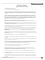
5.08: Modifications to NFPA-54, Chapter 10
(2) Revise 10.8.3 by adding the following additional requirements:
(a) For all side wall horizontally vented gas fueled equipment installed in every dwelling, building or structure used in whole or in part for
residential purposes, including those owned or operated by the Commonwealth and where the side wall exhaust vent termination is less than
seven (7) feet above finished grade in the area of the venting, including but not limited to decks and porches, the following requirements shall
be satisfied:
1. INSTALLATION OF CARBON MONOXIDE DETECTORS. At the time of installation of the side wall horizontal vented gas fueled
equipment, the installing plumber or gasfitter shall observe that a hard wired carbon monoxide detector with an alarm and battery back-up is
installed on the floor level where the gas equipment is to be installed. In addition, the installing plumber or gasfitter shall observe that a battery
operated or hard wired carbon monoxide detector with an alarm is installed on each additional level of the dwelling, building or structure
served by the side wall horizontal vented gas fueled equipment. It shall be the responsibility of the property owner to secure the services of
qualified licensed professionals for the installation of hard wired carbon monoxide detectors
a. In the event that the side wall horizontally vented gas fueled equipment is installed in a crawl space or an attic, the hard wired carbon
monoxide detector with alarm and battery back-up may be installed on the next adjacent floor level.
b. In the event that the requirements of this subdivision can not be met at the time of completion of installation, the owner shall have a period of
thirty (30) days to comply with the above requirements; provided, however, that during said thirty (30) day period, a battery operated carbon
monoxide detector with an alarm shall be installed.
2. APPROVED CARBON MONOXIDE DETECTORS. Each carbon monoxide detector as required in accordance with the above provisions
shall comply with NFPA 720 and be ANSI/UL 2034 listed and IAS certified.
3. SIGNAGE. A metal or plastic identification plate shall be permanently mounted to the exterior of the building at a minimum height of eight
(8) feet above grade directly in line with the exhaust vent terminal for the horizontally vented gas fueled heating appliance or equipment. The
sign shall read, in print size no less than one-half (1/2) inch in size, "GAS VENT DIRECTLY BELOW. KEEP CLEAR OF ALL
OBSTRUCTIONS".
4. INSPECTION. The state or local gas inspector of the side wall horizontally vented gas fueled equipment shall not approve the installation
unless, upon inspection, the inspector observes carbon monoxide detectors and signage installed in accordance with the provisions of 248 CMR
5.08(2)(a)1 through 4.
(b) EXEMPTIONS: The following equipment is exempt from 248 CMR 5.08(2)(a)1 through 4:
1. The equipment listed in Chapter 10 entitled "Equipment Not Required To Be Vented" in the most current edition of NFPA 54 as adopted by
the Board; and
2. Product Approved side wall horizontally vented gas fueled equipment installed in a room or structure separate from the dwelling, building or
structure used in whole or in part for residential purposes.
(c) MANUFACTURER REQUIREMENTS - GAS EQUIPMENT VENTING SYSTEM PROVIDED. When the manufacturer of Product
Approved side wall horizontally vented gas equipment provides a venting system design or venting system components with the equipment, the
instructions provided by the manufacturer for installation of the equipment and the venting system shall include:
1. Detailed instructions for the installation of the venting system design or the venting system components; and
2. A complete parts list for the venting system design or venting system.
(d) MANUFACTURER REQUIREMENTS - GAS EQUIPMENT VENTING SYSTEM NOT PROVIDED. When the manufacturer of a
Product Approved side wall horizontally vented gas fueled equipment does not provide the parts for venting the flue gases, but identifies
"special venting systems", the following requirements shall be satisfied by the manufacturer:
1. The referenced "special venting system" instructions shall be included with the appliance or equipment installation instructions; and
2. The "special venting systems" shall be Product Approved by the Board, and the instructions for that system shall include a parts list and
detailed installation instructions.
(e) A copy of all installation instructions for all Product Approved side wall horizontally vented gas fueled equipment, all venting instructions,
all parts lists for venting instructions, and/or all venting design instructions shall remain with the appliance or equipment at the completion of
the installation.
MA Code - CO Detector
(for the State of Massachusetts only)

8
L540PB-2 / HZI540PB-2 Direct Vent Gas Insert
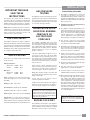
INSTALLATION
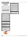
IMPORTANT MESSAGE
SAVE THESE
INSTRUCTIONS
The L540PB / HZI540PB Gas Inserts must be
installed in accordance with these instructions.
Carefully read all the instructions in this manual
fi rst. Consult the "authority having jurisdiction" to
determine the need for a permit prior to starting the
installation. It is the responsibility of the installer to
ensure this fi replace is installed in compliance with
manufacturers instructions and all applicable codes.
BEFORE YOU START
Safe installation and operation of this appliance
requires common sense, however, we are required
by the Canadian Safety Standards and ANSI
Standards to make you aware of the following:
CLOTHING OR OTHER FLAMMABLE
MATERIAL SHOULD NOT BE PLACED
ON OR NEAR THE APPLIANCE.
CHILDREN AND ADULTS SHOULD BE
ALERTED TO THE HAZARDS OF HIGH
SURFACE TEMPERATURES, ESPE-
CIALLY THE FIREPLACE GLASS, AND
SHOULD STAY AWAY TO AVOID BURNS
OR CLOTHING IGNITION.
INSTALLATION AND REPAIR SHOULD
BE DONE BY AN AUTHORIZED
SERVICE PERSON. THE APPLIANCE
SHOULD BE INSPECTED BEFORE
USE AND AT LEAST ANNUALLY BY A
PROFESSIONAL SERVICE PERSON.
MORE FREQUENT CLEANING MAY
BE REQUIRED DUE TO EXCESSIVE
LINT FROM CARPETING, BEDDING
MATERIAL, ETC. IT IS IMPERATIVE THAT
CONTROL COMPARTMENTS, BURNERS
AND CIRCULATING AIR PASSAGEWAYS
OF THE APPLIANCE BE KEPT CLEAN.
DUE TO HIGH TEMPERATURES, THE
APPLIANCE SHOULD BE LOCATED
OUT OF TRAFFIC AND AWAY FROM
FURNITURE AND DRAPERIES.
WARNING: FAILURE TO INSTALL THIS
APPLIANCE CORRECTLY WILL VOID
YOUR WARRANTY AND MAY CAUSE A
SERIOUS HOUSE FIRE.
YOUNG CHILDREN SHOULD BE CARE-
FULLY SUPERVISED WHEN THEY ARE
IN THE SAME AREA AS THE APPLI-
ANCE. TODDLERS, YOUNG CHILDREN
AND OTHERS MAY BE SUSCEPTIBLE
TO ACCIDENTAL CONTACT BURNS. A
PHYSICAL BARRIERS IS RECOMMEND-
ED IF THERE ARE AT RISK INDIVIDUAL
IN THE HOUSE. TO RESTRICT ACCESS
TO A FIREPLACE OR STOVE, INSTALL
AN ADJUSTABLE SAFETY GATE TO
KEEP TODDLERS, YOUNG CHILDREN
AND OTHER AT RISK INDIVIDUALS OUT
OF THE ROOM AND AWAY FROM HOT
SURFACES.

L540PB-2 / HZI540PB-2 Direct Vent Gas Insert
9
INSTALLATION
IMPORTANT MESSAGE
SAVE THESE
INSTRUCTIONS
The Regency Gas Insert must be installed in
accordance with these instructions. Carefully read
all the instructions in this manual fi rst. Consult the
building authority having jurisdiction to determine
the need for a permit prior to starting the installation.
NOTE: Failure to follow the instructions could cause
a malfunction of the heater which could result in
death, serious bodily injury, and/or property damage.
Failure to follow these instructions may also void
your fi re insurance and/or warranty.
FOR YOUR SAFETY
This appliance requires air for proper combustion.
Always provide adequate combustion and ventilation
air. Follow instructions and information in CAN/CGA
B149 (in Canada) or the National Fuel Gas Code
ANSI Z223.1 (in the USA), regarding requirements
for combustion and ventilation air.
SPECIFICATIONS
At pressures over 1/2 psig, the pipe to the unit must
be disconnected.
Gas Input Capacity:
Natural Gas 38,000 Btu/h
Propane 38,000 Btu/h
Min. Input
Natural Gas 25,000 Btu/h
Propane 30,000 Btu/h
Fuels: Approved for use with both natural gas,
and propane. Approved as is for use at 0' to 4,500'
(0-1370m).
Electrical: 120V A.C. system.
Circulation Fan: Variable speed, 140 CFM.
Log Set: Ceramic fi bre, 7 per set - L540PB
Glass Crystals: 8 lbs of glass crystals - HZI540PB
Vent System: 3" x 4" The effi ciency rating of the
appliance is a product thermal effi ciency rating de-
termined under continuous operating conditions and
was determined independent of any installed system.
GAS PRESSURE
TESTING
The appliance must be isolated from the gas sup-
ply piping system by closing its individual manual
shut off valve during any pressure testing of the
gas supply piping system at test pressures equal
to or less than 1/2 psig. (3.45 kPa).
INSTALLATION INTO A
SOLID FUEL BURNING
FIREPLACE OR
FACTORY BUILT
FIREPLACE
The L540PB / HZI540PB Gas Inserts have
been tested and approved to be vented into any
masonry fi replace or approved solid fuel burning
factory built fi replace that will allow the insert to
physically fi t into the fi rebox. Refer to "Minimum
Fireplace Dimensions" section for minimum
fi replace clearances.
If the factory built fi replace* height is too low for
your Insert, you may remove the smoke baffl e
plate, damper, refractory (fi rebricks), glass doors,
screen rails, screen mesh and log grates from the
factory built fi replace as long as these items are
saved and are reinstalled in the event that the
Insert is removed.
Smoke shelves, shields and baffl es may be
removed if attached by mechanical fasteners.
If any part is removed it must not weaken the
structural integrity of the factory built fi replace.
NOTE: Any alterations made to the listed solid
fuel burning factory built fi replace may void the
listing of the fi replace.
*Check with your local inspector before
commencing with this installation.
BEFORE YOU START
Safe installation and operation of this appliance
requires common sense, however, we are required
by the Canadian Safety Standards and ANSI
Standards to make you aware of the following:
General Safety Information
1) The appliance installation must conform with
local codes or in the absence of local codes,
with CAN/CGA B149 (in Canada) or the National
Fuel Gas Code ANSI Z223.1 in the U.S.A. This
appliance should be installed by a qualifi ed gas
fi tter technician only.
2) Installation and repair should be done by a
qualifi ed service person.
3) The appliance should be inspected before use
and at least annually by a professional service
person. More frequent cleaning may be required
due to excessive lint from carpeting, bedding
material, animal hair, etc. It is imperative that
control compartments, burners and circulating
air passageways of the appliance be kept clean.
4) See general construction and assembly
instructions. This appliance may only be installed
in a vented, noncombustible fi replace.
5) This appliance is Listed for bedroom installations
when used with a Listed Millivolt Thermostat.
Some areas may have further requirements,
check local codes before installation.
6) Always connect this insert to a vent system
venting to the outside of the building envelope.
Never vent to another room or inside a building.
Make sure that the vent is properly sized and is
of adequate height to provide the proper draft.
7) Inspect the venting system annually for blockage
and any signs of deterioration.
8) Any glass removed for servicing must be
replaced prior to operating the appliance.
9) To prevent injury, do not allow anyone who is
unfamiliar with the operation to use the fi replace.
10) Due to high temperatures, the appliance should
be located out of high traffi c areas and away
from furniture and draperies. Children and
adults should be alerted to the hazards of high
surface temperatures, especially the fi replace
glass and gold trims, and should stay away to
avoid burns or clothing ignition. Young children
should be carefully supervised when they are
in the same room as the appliance. Clothing or
other fl ammable material should not be placed
on or near the appliance.
Emissions from burning wood or gas could
contain chemicals known to the State of
California to cause cancer, birth defects
or other reproductive harm.
Installer must mechanically attach the supplied
label to the inside of the fi rebox of the fi replace
into which the gas fi replace insert is installed.
"WARNING: This fireplace has been
converted for use with a gas fi replace insert
only and cannot be used for burning wood or
solid fuels unless all original parts have been
replaced, and the fi replace re-approved by the
authority having jurisdiction."

10
L540PB-2 / HZI540PB-2 Direct Vent Gas Insert
INSTALLATION
MATERIALS REQUIRED
Electrical power supply (120V) for the fan to operate. Plug the 3 wire cord
into a suitable receptacle. Do not cut the ground terminal off under any
circumstances. When connected with 120 volts, the appliance must be
electrically grounded in accordance with local codes, current version of CSA
C22.1 (in Canada) or in the absence of local codes, with the National Electrical
Code ANSI/NFPA 70-1987.
INSTALLATION
CHECKLIST
Before installing vent system ensure that the damper plate is open and secure
to prevent the damper plate from falling down and crushing the liner.
The Regency Gas Insert is installed as listed.
1) Check all clearances to combustibles, (Refer to sections "Minimum
Fireplace Dimensions and Clearances to Combustibles)
2) Make the gas connection. (Refer to section "Gas Connection") Gas
connection is on the left side of the appliance.
3) Install the two fl ue liners (intake and exhaust) to the sliding connector
plate. (Refer to section "Flue Liner Installation.")
4) Slide the unit half way into the fi replace.
5) Pull the vent connector plate through the brackets and fasten to the front
plate. Refer to section "Flue Liner Installation.")
6) Slide the unit fully into the fi replace. Level if necessary.
7) Test gas pressure (Refer to section "Gas Pipe Pressure Testing"). Check
aeration system (Refer to section "Gas Insert Aeration System").
8) Install standard and optional features. Refer to the following sections:
a. Brick Panels
b. Enamel Panels
c. Log Set
d. Glass Crystals
e. Spa stones
f
1
. Low Profi le Faceplate with Optional Screen
f
2
. Full Screen Door
g. Remote Control
9) Code remote control. See Remote Control Instruction Manual.
10) Final check: Before leaving this unit with the customer, the installer must
ensure that the appliance is fi ring correctly. This includes:
a) Clocking the appliance to ensure the correct fi ring rate.
b) Adjusting the primary air, if required, to ensure that the fl ame does
not carbon. See "Gas Insert Aeration System" section.
c) Ensuring that the appliance is venting correctly.
A
B
C
D
E
F
C
D
G
C
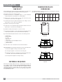
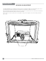
MINIMUM FIREPLACE
DIMENSIONS
The minimum fi replace clearances & dimensions for the Regency gas insert
are shown in the following diagrams:
Max
Lentil Bar
Depth
A
Height
B
Overall
Depth
C
Width
(rear)
D
Width
(front)*
E
Front
Depth
(prior to
taper)
F
Width
(front)*
G
Low
Profi le
Face-
plate
10 24" 17-1/4" 26" 36" 3-1/2" 38-11/16"
Side View
Top View
Top View

L540PB-2 / HZI540PB-2 Direct Vent Gas Insert
11
INSTALLATION
Door
Opening
16" Min
From Top of
24
26
28
30
32
34
36
38
0
2
4
6
8
10
12
14
16
18
20
22
24
Allowable
Mantel Area
)URPERWWRP
RIXQLW
22
20
18
16
Door
Opening
12" Min
From Top of
24
26
28
30
32
34
36
38
0
2
4
6
8
10
12
14
16
18
20
22
24
Allowable
Mantel Area
)URPERWWRP
RIXQLW
22
20
18
16
14
12
A
C
B
E
K
D
L
G
M
Diagram 1
Diagram 3
Diagram 2
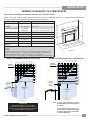
Note: A 3-1/2" mantel defl ector to reduce
mantel height to 36" from bottom of unit
@ 1"depth.
A noncombustible mantel may be
installed at a lower height if the framing
is made of metal studs covered with a
noncombustible board.
MINIMUM CLEARANCES TO COMBUSTIBLES
The clearances listed below are Minimum distances unless otherwise stated:
A major cause of fi res is failure to maintain required clearances (air space) to combustible materials. It is of the greatest importance that this
decorative gas appliance be installed only in accordance with these instructions.
Clearance: Dimension Measured From:
A: Sides
12" / 305 mm From inside edge of faceplate / doors
B: Ceiling
60" / 1524 mm Bottom of unit
C: Mantel (Min. Height)*
*12" / 305mm
16"/ 406mm
From top of unit, or 36" from bottom of unit
From top of unit, or 40" from bottom of unit
D: Min. Hearth Depth
14" / 356mm
E: Min. Hearth Width
44"/ 1016mm
G: Max. Mantle Depth
12" / 305 mm @ 48" (1219mm) from bottom of unit
K: Min. Alcove Width
56" / 1422 mm
L: Max. Alcove Depth
36" / 914 mm
M: Optional mantel
defl ector
3-1/2" / 89mm
Notes: Non-combustible hearth required. If unit is raised 6" from the fl oor - no hearth is
required.
Otherwise:
Min. Hearth requirements - An R value of 1.75 is required to meet the requirements of the
hearth in front of this appliance. 1" of Calcium Silicate board available from Regency, part
number (296-936) plus 3/8" tile or equivalent would meet this requirement.
See part instruction sheet 919-133 for non-combustible Calcium Silicate board requirements.
MANTEL CLEARANCES WITHOUT DEFLECTOR MANTEL CLEARANCES WITH 3-1/2" DEFLECTOR
WARNING
Although this appliance passes safety
certifi cation, the hearth in front of the fi replace
becomes very hot when the fi replace heats. Do
not use the hearth as a seat or shelf.

12
L540PB-2 / HZI540PB-2 Direct Vent Gas Insert
INSTALLATION
VENTING
THE APPLIANCE MUST NOT BE
CONNECTED TO A
CHIMNEY FLUE SERVING A
SEPARATE SOLID FUEL
BURNING APPLIANCE.
This appliance is designed to be attached to a
3" intake and a 4" exhaust aluminium fl ex vent.
The fl ue length must be a minimum length of 8 '
(2.44m) and a maximum of 35' (10.7m). See chart
for minimum distances from roof. Periodically check
that the vent is unrestricted.
Masonry chimneys may take various contours which
the fl exible liner will accommodate. However, keep
the fl exible liner as straight as possible, avoid
unnecessary bending.
GAS CONNECTION
1) If the appliance is to be installed into an existing
chimney system, thoroughly clean the masonry
or factory built fi replace.
2) The appliance is provided with an opening on
the left hand side of the control compartment.
A 3/8" NPT gas supply pipe must be brought
near this inlet hole.
3) Locate the center point where the vent will pass
through the chimney above the appliance. Move
the appliance into the exact location where it is
to be installed. Ensure that the Insert is level.
4) Do not cut any sheet-metal parts of the fi re-
place, in which the gas fi replace insert is to
be installed.
5) If the factory-built fi replace has no gas access
hole(s) provided, an access hole of 1-1/2"
(37.5mm) or less may be drilled though the
lower sides or bottom of the fi rebox in a
proper workmanship like manner. This access
hole must be plugged with a non-combustible
insulation after the gas supply line has been
installed.
Air Intake pipe and exhaust must be attached to
the inlet and exhaust collars of the appliance with
a minimum of three screws per pipe.
GAS CONNECTION WARNING:
Only persons licensed to work
with gas piping may make the
necessary gas connections
to this appliance.
3" Air
Intake
4" Exhaust
Flue
The Air Intake and exhaust pipes must be attached
to the inlet and exhaust collars of the termination
cap with a minimum of three screws per pipe.
Part # Description
948-305 3" Flex - 35 ft. (Air intake)
948-336 4" Flex - 35 ft. (exhaust)
946-588 Co-linear DV Vertical Termination Cap
NOTE: Flashing should be securely
fastened to the chimney.

L540PB-2 / HZI540PB-2 Direct Vent Gas Insert
13
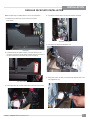
INSTALLATION
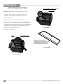
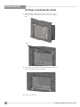
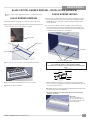
1) Detach the Flue Connector Plate from the unit by removing the
Connector Plate Screws and sliding the Flue Connector Plate forward
and off the unit.
NOTE: Flue Plate Connector Gasket
must not be damaged or removed.
Care must be taken to ensure that this
gasket remains intact to prevent fl ue
leakage.
5) When the Flue Connector Plate is close to the front of the unit, engage
the Flue Connector Screws and carefully tighten the Flue Connector
Plate the fi nal amount.
** Make sure the Rear Tabs connect into their respective slots in the Flue
Connector Plate. Failure to do so will result in fl ue gas leakage and
degrade the operation of the unit ** (See diagram below of location.)
The Flue connection is complete when the Flue Connector Plate is fully
forward and the Rear Tabs are fully engaged.
6) Remove the Flue Connector Tool and store for future use.
2) Attach the Flue Liners onto the Flue Connector Plate using non RTV
type sealant, then fasten with 3 screws.
See the section in this manual on Venting installation.
3) Position the unit in front of the fi replace opening, start the Flue Connec-
tor Plate into the Flue Connector Plate Guides.
Flue Connector Plate
Flue Connector Slide Tool
Connector plate screws
4) Use the Flue Connector Slide Tool to slowly pull the Flue Connector
Plate forward as you move the Insert rearward into the Fireplace Chase.
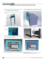
FLUE / VENT INSTALLATION
WARNING:
Failure to position the parts in accordance with these diagrams or failure
to use only parts specifi cally approved with this appliance may result in
property damage or personal injury.
Connecting the Vent Liners
Intake Liner
Exhaust Liner
Vent Connectors
Flue Connector
Plate Gasket
Flue Connector
Plate Guides
Flue Connector
Slide Tool
Flue Connector
Screws
Flue Connector
Plate

14
L540PB-2 / HZI540PB-2 Direct Vent Gas Insert
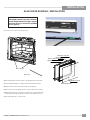
INSTALLATION
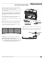
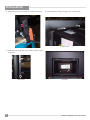
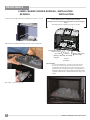
LEVELING LEG ADJUSTMENT
The L540PB / HZI540PB inserts are equipped with 2 levelling legs that are accessible while the appliance is in its fi nal installation position. The unit
can be adjusted up to 5/8" (16mm). The faceplate must not be installed to do this adjustment, if installed, remove faceplate.
Remove left and right inner panels by sliding them forward. The rear levelling bolts are located in the back corners of the fi rebox and can be adjusted
using a 7/16" wrench. Rotate the bolts clockwise to raise the rear of the fi rebox.
When the appliance is in position, adjust the bolts to level the appliance, making sure that the appliance is also level and is sitting on both bolts to
prevent rocking.
Leveling Bolts

L540PB-2 / HZI540PB-2 Direct Vent Gas Insert
15
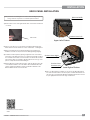
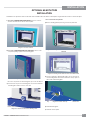
INSTALLATION
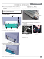
Air Shutters are required to increase or decrease the amount of air that is
mixed with the fuel before combustion. This will have an affect on how well
the fuel combusts and how the fl ame physically appears.
Low primary air will leave a taller, yellower fl ame while higher primary air will
leave a lower, bluer fl ame.
This setting is largely for appearance, however, not enough primary air may
lead to carboning, sooting or a fl ame that reaches the top of the fi rebox.
Situations that may require more primary air are; units that are burning
propane, units installed at higher elevations or units that are run on high
most of the time.
The L540PB / HZI540PB is equipped with an air shutter that is accessible
from outside the fi rebox and can be adjusted during operation.
Aeration adjustments should only be made after the unit has been on for 30
minutes to 1 hour.
Slide the Air Shutter Lever towards you to increase the primary air setting.
Slide the Air Shutter away from you to decrease the primary air setting.
Below you will see a chart showing the minimum primary air settings.
These are set from the factory, but due to fuel conversions or installation
conditions, the air setting may need to be adjusted.
Close
Open
Unit Fuel Type Min. Air Setting
L540PB NG 1/8" (3mm)
L540PB LP 3/8" (9mm)
HZI540PB NG 1/8" (3mm)
HZI540PB LP 3/8" (9mm)
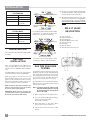
AIR SHUTTER ADJUSTMENT
1) Slide the Air Shutter Lever towards you to increase the primary air set-
ting.
2) Slide the Air Shutter away from you to decrease the primary air setting.
Below you will see a chart showing the minimum primary air settings.
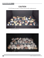
CAUTION: Carbon will be produced if air shutter is closed too much.
Note: any damage due to carboning resulting from improperly setting
the aeration controls is NOT covered under warranty.
Note: Aeration Adjustment should only be performed by an authorized
Regency Installer at the time of installation or service.
Push to close - Pull to open
Unit Front
Unit Back
Air Shutter
Burner Mounting
Bracket
Gas Orifice
Air Shutter Lever
Firebox cut-away
to show location
of the Air Shutter

16
L540PB-2 / HZI540PB-2 Direct Vent Gas Insert
INSTALLATION
L540PB-NG / HZI540PB-NG
SYSTEM DATA
Min. Supply Pressure 5" WC (1.25 kpa)
Manifold Pressure 3.5" WC (0.87 kpa)
Orifi ce Size #32 DMS
Maximum Input 38,000 Btu/h
(11.14 kW)
L540PB-LP / HZI540PB-LP
SYSTEM DATA
Min. Supply Pressure 11" WC (2.73 kpa)
Manifold Pressure 10" WC (2.49 kpa)
Orifi ce Size #51 DMS
Maximum Input 38,000 Btu/h
(11.14 kW)
GAS PIPE PRESSURE
TESTING
The appliance must be isolated from the gas sup-
ply piping system by closing its individual manual
shut-off valve during any pressure testing of the
gas supply piping system at test pressures equal
to or less than 1/2 psig. (3.45 kPa). Disconnect
piping from valve at pressures over 1/2 psig.
The manifold pressure is controlled by a regulator
built into the gas control, and should be checked
at the pressure test point.
Note: To properly check gas pressure, both
inlet and manifold pressures should
be checked using the valve pressure
ports on the valve.
1) Make sure the valve is in the "OFF" position.
2) Loosen the "IN" and/or "OUT" pressure tap(s),
turning counterclockwise with a
1/8" wide fl at screwdriver.
3) Attach manometer to "IN" and/or "OUT"
pressure tap(s) using a 5/16" ID hose.
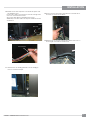
4) Light the pilot and turn the valve to "ON"
position.
HIGH ELEVATION
This unit is approved for altitude 0 to 4500 ft. (CAN1
2.17-M91).
GAS LINE
INSTALLATION
Since some municipalities have additional local
codes it is always best to consult with your local
authorities and the CAN/CGA B149 installation
code.
For USA installations follow local codes and/or the
current National Fuel Gas Code, ANSI Z223.1.
When using copper or fl ex connectors use only
approved fi ttings. Always provide a union so that
gas lines can be easily disconnected for servicing.
Flare nuts for copper lines and fl ex connectors are
usually considered to meet this requirement.
NOTE: A shutoff / dante valve should be sup-
plied in or near the unit (or as per local codes)
for ease of servicing this appliance.
IMPORTANT: Always check for gas leaks with
a soap and water solution or gas leak detector.
Do not use open fl ame for leak testing.
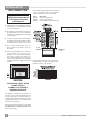
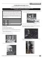
820 S.I.T. VALVE
DESCRIPTION
Top View of pilot fl ame
Top View of pilot fl ame
Incorrect fl ame pattern will have small, probably
yellow fl ames, not coming into proper contact
with the rear of the burner or thermopile.
If you have an incorrect fl ame pattern, contact
your Regency dealer for further instructions.
5) The pressure check should be carried out with
the unit burning and the setting should be within
the limits specifi ed on the safety label.
6) When fi nished reading manometer, turn off the
gas valve, disconnect the hose and tighten the
screw (clockwise) with a 1/8" fl at screwdriver.
Note: Screw should be snug, but do not over
tighten.
1
2
3
4
5
IN OUT
7
8
6
1) Gas on/off knob
2) High/low adjustment
3) Pilot Adjustment
4) Manifold (Outlet) Pressure Tap
5) Inlet Pressure Tap
6) Pilot Outlet
7) Main Gas Outlet
8) Alternative TC Connection Point

L540PB-2 / HZI540PB-2 Direct Vent Gas Insert
17
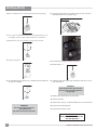
INSTALLATION
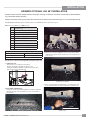
CONVERSION FROM NG TO LP
L540PB/HZI540PB using SIT 820 NOVA Gas Valve
Before you begin:
Shut off the gas supply to the unit.
Disconnect all electrical supply to the unit.
Always let the appliance cool to room temperature before servicing.
1. Remove Faceplate, backing plate, glass door, and inner panels (see
manual for detailed instructions).
2. Remove the wire clip below the pilot cap.
WARNING
This conversion kit shall be installed by a qualifi ed service agency in
accordance with the manufacturer’s instructions and all applicable codes
and requirements of the authority having jurisdiction. If these instructions
is not followed exactly, a fi re, explosion or production of carbon monoxide
may result causing property damage, personal injury or loss of life. The
qualifi ed service agency is responsible for the proper installation of this
kit. The installation is not proper and complete until the operation of the
converted appliance is checked as specifi ed in the manufacturer’s instruc-
tions supplied with the kit.
THIS CONVERSION MUST BE DONE BY A QUALIFIED GAS FITTER
IF IN DOUBT DO NOT DO THIS CONVERSION!
Conversion Kit includes:
1 904-964 Orifi ce #51
1 918-590 Decal - Conversion to LP
1 908-528 Label Propane
1 910-037 Pilot Orifi ce
1 904-529 Allen Key
3. Pull off the pilot cap to expose the pilot orifi ce.
4. Unscrew the pilot orifi ce with the allen key; then replace with the LPG pil
o
orifi ce, provided in the kit.
5. Remove burner - see burner removal section in manual.
6. Using a 3/8” socket wrench, loosen and remove the main gas orifi ce.
Replace with the LP gas orifi ce. Confi rm the orifi ce size marked on the
Orifi ce with the Rating Label on the appliance
7. Locate the valve on the left hand side of the unit. Pull off the Hi/Lo gas
extension knob to access the hex screw.

18
L540PB-2 / HZI540PB-2 Direct Vent Gas Insert
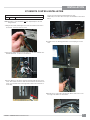
INSTALLATION
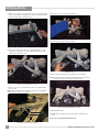
13. Verify that if the conversion is from NG to LPG, the screw must be re-
assembled with the red o-ring visible (Fig. 5).
LPG Configuration
Red o-ring visible
Fig.5
14. Re-assemble the black protection cap (Fig. 6).
15. Reverse steps 5 - 1.
Fig. 6
WARNING!
Also check that the pilot and main
burner injectors are appropriate for
the gas type.
17. Replace yellow "NG" label with red "LPG" label.
18. Check for gas leaks.
19. Adjust aerations settings - see Air Shutter Adjustment section in the manual.
20. Check inlet and outlet pressures.
21. Check operation of fl ame control.
16. Attach the label "This unit has been converted to LPG" near or on top
of the serial # decal.
Fi
g
.2
12. Using the Allen wrench as shown in Fig. 4, rotate the screw clockwise until
snug, do not overtighten.
Fig.4
Fig.3
9. Insert a 5/32” or 4mm Allen wrench into the hexagonal key-way of the
screw (Fig. 2), rotate it counter-clockwise until it is free and extract it.
10. Check that the screw is clean and if necessary remove any dirt.
11. Flip the screw (Fig. 3).
WARNING!
Do not over tighten the screw.
Recommended to
grip the wrench by the short side.
Fig. 1
8. Remove the black protection cap by hand from the hi-low knob (Fig.1).
Installer Notice:
These instructions must be left
with the appliance
.

L540PB-2 / HZI540PB-2 Direct Vent Gas Insert
19
INSTALLATION
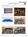
GT REMOTE CONTROL INSTALLATION
Note: GT remote control installation must be completed prior to the unit
being installed.
1. Bring the TH, TPTH, and Stepper motor wires around back of the unit to
the left side - where the valve is located.
GT Remote Receiver Components
1 946-680 GT remote control
2. Connect the TH/TP-TH wires from the harness to the valve terminals also
marked TH/TP-TH - locations as shown below.
3. Secure cable ties to the unit as shown by inserting cable ties into round
holes. There will be a total of 4 cable ties that need to be inserted into the
holes. (2 on the back and 2 on the right side located on the lower side of
the fi rebox).
TPTH Wire
TH Wire
Secure wires with cable ties installed in previous step.
Additionally secure wires with a wire clip to be installed in location sho
w
below.
Cable Tie
Wire Clip
Left
Right
Cable Tie
Cable Tie
4. Install receiver onto backing plate with 2 screws and plug in receiver
wires.
5. Bundle excess receiver wire using the 4th cable tie and secure to the
front right of the fi rebox as shown below.

20
L540PB-2 / HZI540PB-2 Direct Vent Gas Insert
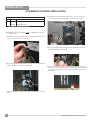
INSTALLATION
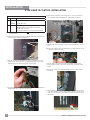
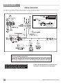
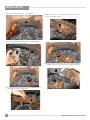
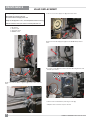
GTM REMOTE CONTROL INSTALLATION
Note: GTM remote control installation must be completed prior to the unit
being installed.
1. Bring the TH, TPTH, and Stepper motor wires around back of the unit to
the left side - where the valve is located.
GTM Remote Receiver Components
1 946-681 GTM remote control
1 946-683
(or)
946-984
Stepper Motor (NG)
Stepper Motor (LP)
2. Connect the TH/TP-TH wires from the harness to the valve terminals also
marked TH/TP-TH - locations as shown below.
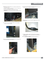
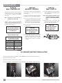
3. Install stepper motor (installation instructions provided by SIT) - reinstall
valve.
6. Connect the stepper motor wire (marked stepper) from the harness into
the stepper motor wire on the motor.
9. Secure cable ties to the unit as shown by inserting cable ties into round
holes. There will be a total of 4 cable ties that need to be inserted into th
e
holes. (2 on the back and 2 on the right side located on the lower side of
the fi rebox).
TPTH Wire
TH Wire
4. Valve must be removed to install stepper motor - loosen 4 screws that
secure the Gas Valve Mounting bracket, slide bracket up to release.
La page est en cours de chargement...
La page est en cours de chargement...
La page est en cours de chargement...
La page est en cours de chargement...
La page est en cours de chargement...
La page est en cours de chargement...
La page est en cours de chargement...
La page est en cours de chargement...
La page est en cours de chargement...
La page est en cours de chargement...
La page est en cours de chargement...
La page est en cours de chargement...
La page est en cours de chargement...
La page est en cours de chargement...
La page est en cours de chargement...
La page est en cours de chargement...
La page est en cours de chargement...
La page est en cours de chargement...
La page est en cours de chargement...
La page est en cours de chargement...
La page est en cours de chargement...
La page est en cours de chargement...
La page est en cours de chargement...
La page est en cours de chargement...
La page est en cours de chargement...
La page est en cours de chargement...
La page est en cours de chargement...
La page est en cours de chargement...
La page est en cours de chargement...
La page est en cours de chargement...
La page est en cours de chargement...
La page est en cours de chargement...
La page est en cours de chargement...
La page est en cours de chargement...
La page est en cours de chargement...
La page est en cours de chargement...
-
 1
1
-
 2
2
-
 3
3
-
 4
4
-
 5
5
-
 6
6
-
 7
7
-
 8
8
-
 9
9
-
 10
10
-
 11
11
-
 12
12
-
 13
13
-
 14
14
-
 15
15
-
 16
16
-
 17
17
-
 18
18
-
 19
19
-
 20
20
-
 21
21
-
 22
22
-
 23
23
-
 24
24
-
 25
25
-
 26
26
-
 27
27
-
 28
28
-
 29
29
-
 30
30
-
 31
31
-
 32
32
-
 33
33
-
 34
34
-
 35
35
-
 36
36
-
 37
37
-
 38
38
-
 39
39
-
 40
40
-
 41
41
-
 42
42
-
 43
43
-
 44
44
-
 45
45
-
 46
46
-
 47
47
-
 48
48
-
 49
49
-
 50
50
-
 51
51
-
 52
52
-
 53
53
-
 54
54
-
 55
55
-
 56
56


Regency Fireplace Products Horizon HZI540PB Le manuel du propriétaire
- Catégorie
- Cheminées
- Taper
- Le manuel du propriétaire
- Ce manuel convient également à
dans d''autres langues
Documents connexes
-
 Regency Fireplace Products Horizon HZI540EB Le manuel du propriétaire
-
 Regency Fireplace Products Horizon HZI390PB Le manuel du propriétaire
-
 Regency Fireplace Products Alterra CF780 Le manuel du propriétaire
-
 Regency Fireplace Products Plateau PTO30CFT Le manuel du propriétaire
-
 Regency Fireplace Products Horizon HZI540EB Le manuel du propriétaire
-
 Regency Fireplace Products Horizon HZI540EB Le manuel du propriétaire
-
 Regency Fireplace Products HZI390E-NG Le manuel du propriétaire
-
 Regency Fireplace Products Horizon HZI390EB Le manuel du propriétaire
-
 Regency Fireplace Products Energy U23 Le manuel du propriétaire


Autres documents
-
Breckwell Hearth AH2613i Manuel utilisateur
-
-
-
Regency U31-NG10 Manuel utilisateur
-
Regency Energy E33 Series Gas Insert Manuel utilisateur
-
SCAN 45i Installation And Operation Instructions Manual
-
Regency L540EB-NG Owners & Installation Manual
-
BN-LINK U48 Le manuel du propriétaire
-
Pacific energy Broadway Installation And Operating Instructions Manual
-
 Lennox Hearth Gas Stove Manuel utilisateur
