Genie 2562 Guide d'installation
- Catégorie
- Porte de garage
- Taper
- Guide d'installation
Ce manuel convient également à

P/N 37068500118
11-10
POWERHEAD
LATETED'ALIMENTATION
CIRCUIT ELECTRI(
Safe-T-Beam ®
Trombones de fil (4
RAIL
C IV O L
VISSER DES MODELES MOTIVI S
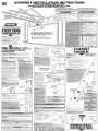
This Opener includes parts and supplies needed to install
in most garages and connect to most garage doors. There
are many variations of garages and garage doors. A few additional parts and
supplies may be needed to install Opener into your garage and connect to your
garage door. While going over the check list below, note any additional items
you will need. For help, find a local Genie®Professional Dealer with 800-OK-GENIE
or call Customer Service at 800-35-GENIE.
porte comprend des pi@ceset des
fournitures n_cessaires pour I'installer dans la
plupart des garages et le conr __r_ la plupart des portes de garage. IIexiste des
nombreuses variantes de garages et de portes desgarage. Quelques pi@ceset fournitures
suppl@mentaires peuvent @tren_cessairesinstaller I'ouvre-porte dans votre garage
et leconnecter _votre porte de garage. Tandis que vous examinez la liste de contrGle
ci-dessous, notez tousles articles suppl@mentaires dont vous aurez besoin. Obtenir
de I'aide, contactez un Genie®local le distributeur professionnel en 800-OKGENIEou
service_ la client@led'appel _ 800-35- GENIE.
CONNECTEUR DE RA
RAIL
RAIL
Safe-T-Beam ®
S
FOR SCREW DRIVE GA
l
V
RELEASE
HANDLE
LA POIGNEE
DE RELACHEMENT
D'URGENCE
HEADER
BRACKET
CROCHET \
DEMUR
ARM
ERAS
DEPORTE
DOOR
CROCHET
DE PORTE
DOORS MADE OF MASONITE, LIGHTWEIGHT WOOD,
FIBERGLASS AND METAL MUST BE PROPERLY
BRACED BEFORE MOUNTING DOOR OPENER.
CONTACT DOOR MANUFACTURER OR DISTRIBUTOR
FOR BRACING INSTRUCTIONS.
LES PORTES FAITES D'AGGLOM#R#, ALLUMENT LE BOIS
DE POIDS, LE FIBRE DE VERRE ET LE MleTAL DOIVENT #TRE
CONVENABLEMENT RENFORC#S AVANT MONTER
D'OPERATEUR DE LA PORTE. CONTACTER LE FABRICANT DE
PORTE OU DISTRIBUTEUR RENFORCER DES INSTRUCTIONS.
S T
S
LA PORTE DE G
I_ READ OWNER'S MANUAL COMPLETELY _" LIRELEMANUELDEPROPRIETAIRECOMPLETEMENT "]
BEFORE INSTALLING GARAGE DOOR OPENER _.. AVANTINSTALLERLOUVRE-BOITESDEPORTEDEGARAGEJ
TINSTALLATI
TOREDUCERISKOFSEVEREINJURYORDEATH:
1 READ AND FOLLOW ALL SAFETY, INSTALLATION AND OPERATION INSTRUCTIONS. If you have any questions or
do not understand an instruction, call local Genie Professional Dealer at 800-OK-GENIE.
2 Do Not install operator on improperly balanced door. Unbalanced door could cause severe injury. Repairs and
adjustments to cables, spring assemblies and other hardware must be made by a trained service person using
proper tools and instructions.
3 Remove all ropes, and disa ble all locks connected to door before installing operator.
4 Install door operator 7 feet or more above floor. Mount Emergency Release Knob 6 feet above floor.
S Do Not connect operator to source power until instructed to do so.
6 Locate Control Button: A. Within sight of door. B.Away from all moving parts of door. C. At minimum height
of 5 feet so small children cannot reach it.
7 Install entrapment WARNING label next to wall control or console. Attach emergency release tag to release lever.
8 Operator must reverse when door contacts a 1-1/2 inch hig h object on floor at center of doorway. This is about
the size ofa 2"x 4" board laid flat.
Safe-T-Beam ®
IMPORTANTESINSTRUCTIONSD'INSTALLATION
®
A o
RI_DUIRELESRISQUESDEBLESSURESGRAVESOUDEMORT,PROCIDEZCOMIVIESUIT',
I LIREETSUIVJREATTENTIVEMENTTOUTESLESiNSTRUCTIONSDINSTALLATION,DEFONCTIONNEMENTETTOUTESLESCONSlGNES
DESECURITE.Sivousavezdesquestionsousivousnecomprenezpasuneinstruction,contactezunprofessionneleninstallation
agr_ parGenie®£800-0KGENIE.
2 NepasinstallerI'op@ateursuruneportemal@uilibr@.Celle-cipourraitentrainerdegravesblessures.Lesr@arationsetles
r_g[agesdesc£bles,ensemblesderessortoutoutautrearticlesdelaquincailleriedoivent@eeffectu_sparunprofessionnelquise
sertdoutilsappropri_setquirespectelesinstructions.
3 Enlevertouteslescordesetd_sactivertouslesverrousdelaporteavantI'instalerI'op@ateur.
4 InstallerI'op_rateurdelaportei 2,1mouplusau-dessusdusol.Placerleboutonded_clenchementd'urgencei unehauteurde1,8m.
S NepasraccorderI'op@ateur£lasourced'alimentationavantI'_tapeendonnantI'instruction.
6 Placerleboutondelacommande:
, ,Envuedelaporte.
, Aunehauteurminimalede1,5mdinquelesjeunesenfantsnepuissentpasI'atteindre.
, loindetoutespi_cesmobilesdelaporte.
7 PlacerI'_tiquetted'AVERTISSEMENTencasdecoin®agei proximit_duboutonoudelaconsolemurale.InstalerI'_tiquettede
d_clenchementd'urgencesurou £proximit_dudlspositifded_clenchementd'urgence.
8 L'op@ateurdolts'inverserIorsquelaporteentreencontactavecunobjetd'unehauteurde3,8cmplac_surlesol,aucentrede
_ I'ouverturedelaporte.Ceci£quivaut£environ£unecolombede2piedspar4po%ei platsurlesol.
POTENTIA[
HAZARD
MOVING
DOOR
ELECTRICAL
SHOCK
HIGH
SPRING
TENSION
EFFECT
WARNING:
Could result
in death or
o .
WARNING:
Could result
in death or
o .
WARNING:
Could result
in death or
o .
PREVENTION
Keep people clear of opening while door
is moving.
Do Not allow children to play with door opener.
Do Not operate adoor that jams or one that hasa
broken spring.
•Turn off power before removing opener cover.
•When replacing cover, make surewires are not
pinched or nearmoving parts.
• Opener must be properly grounded.
• Do Not tryto remove,repairor adjustspringsor
anythingto which door spring partsarefastened,
suchas,wood blockssteelbrackets,cablesor
other likeitems.
•Repairsand adjustmentsmustbe madebya
traineddoor systemtechnicianusingproper
tools andinstructions.
DANGERPOTENTIEL
PORTEEN
MOUVEMENT
CHOC I_LECTRIQUE
TENSION[eLEVI_E
DURESSORT
RI_SULTAT
AVERTISSEMENT:
Celarisque
d'entrainerlamort
oudesblessures
graves.
AVERTISSEMENT:
Celarisque
d'entrainerlamort
0udesblessures
graves.
AVERTISSEMENT:
Celarisque
d'entrainerlamort
0udesblessures
graves.
MESUREDE PRI_VENTION
NelaisserpersonnesetenirdartsI'ouverture
delaportependantqu'elleestmouvement.
Nepaspermettreauxenfantsdejoueravec
I'op#rateurdelaporte.
Nepasfakefonctionneruneportequibloque
oudontleressortestcass&
Mettrehorstensionavantd'enleverle
couvercledeI'op_rateur.
Enrefermantlecouvercle,s'assurerqueles
filsnesontpasnicoinersniprosdepi_cesmobiles.
L'op@ateurdolt_trecorrectementmis,_laterre.
Nepasessayerd'enlever,r@arerouajusterles
ressortsoutouteautrepiece_laquelleleressortde
laporteestattache,ycomprisblocsdebois,supports
enacier,c,iblesouautresarticlessemblables.
Lesr@arationsetlesr_glagesdoivent_treeffectu_s
parunprofessionneldessyst_mesdeportequise
sertd'outilsappropri_setquirespecte
lesinstructions.
f f
PRE-INSTALL
• Tape Measure (12 ft. min.)
PRE-INSTALLATION
• Ruban _ mesurer (12 pieds min.)
PRE-INSTALL
• Pencil
To Complete the PRE-INSTALL
• Ladder
COMPLETER LA PR¢-INSTALLATION
• Crayon • l_chelle
PRE-INSTALLATION
For ASSEMBLY & INSTALLATION
•6' to 7' Step Ladder •Electric Drill • 1/16" and 5/32" Drill Bits • Pliers
•Tape Measure •Adjustable Wrench • Hammer • Rubber Mallet
•Wire Strippers • Phillips Screwdriver • Flat Blade Screwdriver
•Pencil. Safety Glasses • Hacksaw • Carpenter's Level • Socket
Wrench. Short Extension. Sockets-- 3/8", 7/16", 1/2" and 9/16".
Additional tools to make installation easier: Slotted and
phillips screw-driver bits, Stud finder and Sheet metal snips.
Before beg!n.ningassembly and installation,
gather additional items and tools you may need.
Garagedoor bracingor reinforcementkitsincludingbrackets,
screws,etc.(availableat localdealer)
Electricaloutlet within 3feetof dooropenerlocation.(Ifone must
beadded,it mustbesuppliedbylicensedelectrician.)
Sufficientangleiron or strappingfor hangingPowerHead(store)
Lightbulbs(seepowerhead/owner'smanualfor maximumwattage)
Alternativefastenersfor Safe-T-Beam®Brackets(iftheymustbe
attachedto materialother thanwood).
Woodfor header,ceiling,and/ordoor braces(store)
Safe-T-Beam®BracketExtensions(dealer)
Masonrydrill bit (ifyou will beattachingSafe-T-Beam®to floor).(store)
ExtensionKit(for8' Doors)(dealer)
Pour L'INSTALLATION
PRE-INsTALL
©ooR Co_,_Dmo_,_
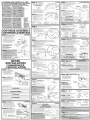
Make sure door, springs and hardware structurally sound, well braced.
Look for broken springs, loose or worn cables or fasteners. Any
questions, contact a Genie®Professional Dealer. Referto door type
shown below.
i i!
i
SECTIONALDOOR
PORTEENSEC__
__..v i_
Torsion Springs -
Ressorts de torsion
J
SECTIONALDOOR _ ExtensionSprings
PORTEENSEC nsion
Center Stile_ _ _ :_1
=ootootceot=,
ONE-PIECEDOOR HeaderArea
(TRACKLESS) Linteau
PORTED'UNEPII_CE
Centt;nStt_; nt rai---_-_ !._____
PRE-INsTALL
@?EBAT/ON AND _ALABICE
1. Raise and lower door manually to ensure free operation. If door
looks missaligned, binds or does not move smoothly, contact
a Genie ® Professional Dealer.
2. If door operates well, raise it again to about 3 or 4 feet above
floor and carefully let go. Door should stay put. Small movement is
okay but, any more and door isconsidered out of balance which
will greatly affect operation of opener.
KEEP FEET
CLEAR
OF DOOR
t
/
J
J
J
J
J
J
J
J
/
Sectional Door
Porte en section
Ifdoor sticks,binds,or isout of balance,haveit adjustedby
garagedoor dealerorGenie®ProfessionalDealer.Do notattempt
to remove,repairor adjustdoor springs,cables,pulleys,brackets
orassociatedhardware.Thesepartsareunder extremetension
and cancauseseriousinjury ordeath.
GARDER LES
PIEDS HORS
DU CHEMIN
DE LA PORTE
One-Piece Door
Porte d'une piece
, ®
Si la porte collie, selie,ou est hors d _quilibre, faites-la ajuster par un concessionnaire de la porte de garage ou unGenie distributeur
professionnel. N'essayezpasd'enlever, de r@arer, ou d'ajuster lesassemblies de ressorts,lesc£bles, lespoulies, lessupports, ou le
materiel associ_de la porte. Cespi_ces sont sous tension extreme et peuvent provoquer des blessuresgraves ou lamort.
PRE-INsTALL
Measure door height (floor to top of door). Opener is designed for doors up to, and including, 7'-6" tall.
If door is taller than 7'-6", contact Genie ®Professional Dealer.
• Forall types and stylesof doors:
- If ceiling in garage isso low that there isnot at least a 3" spaceabove Header Bracketmounting
point see if INsTALLATIoNSTEP1will help, If not contact Genie®Professional Dealer.
• Ifdoor spring isin way, place Header Bracket above spring. De Not move door spring.
• Pourtous types et styles des portes:
Sile plafond dans le garage est si basque I'on n'y a pasau moins 3"d'espace au-dessus point de montage du support de I'embase,
voir siINsTALLATIoN I_TAPE1 aidera. Si non, contactez un Genie®le distributeur professionnel.
• Si le ressort de la porte est dans le chemin, placez le support de I'embase au-dessusdu ressort. Ned@lacez pas le ressort de la porte.
PRE-INSTALL
(This s1.q__o_¢n_Aly_'equR_estwo l_eol_A®)
Find center of door from side to side and mark this point with
vertical line on header or wall above door. Raisedoor while
watching top edge as it moves. Hold door at position where
door's top edge isat highest point and measure distance from
edge down to floor.
Sectional doors, add 2-1/2" to this height and mark it at
center of door. Bottom of header bracket goes here.
One-piece doors, add 6" to this height and mark it at
center of door. Bottom of header bracket goes here.
Checkfor a solid mounting surface at mark.If none,you must
mount one. A 2"x 6" board fastened to wall studs isrecommended.
HIGH-RISE
POINT
LEPLUS
HAUT
POINT
de trajet
HIGH-RISEPOINTPLUS2-1/2"ON
LEPLUSHAUTPOINTde trajet plu 2-1/2" C_E
Y
SECTIONALDOOR
PORTE EN SECTION
HIGH-RISEPOINT PLUS6" ON
LEPLUSHAUTPOINTde trajet plu 6" C_E
HIGH-RISE
POINT
LEPLUSHAUT
POINTde tra
ONE-PIECE DOOR
PORTED'UNE PIECE
Special Circumstance of
Restricted Vertical Space
La circonstance sp{_ciale
d'espace vertical limit_
_MAX. 6" FROMWAL_
MAX. 6" DU MUR
," TORSION 1
, ' SPRING
RESSORT
',, DE TORSION
TOP OF DOOR
LESUMMET ]
HEADER
BRACKET
CROCHET
DE LINTEAU
©
IN LOW OVERHEAD SITUATIONS,
HEADER BRACKETCAN BE MOUNTED
ON CEILING AS SHOWN.
DANSLESSITUATIONSBASSESAU-DESSUSDE
LATETE,LACROCHETDELINTEAUPEUTETRE
MONTESURLEPLAFONDCOMMEIINDIQUE
PRE-INsTALL
IPow_/4_u_D Grounded outlet
_oum:s_,_QAtf_ Prise de courant (_contact de mise (_terre
Check area above where Opener's Power
Head will be mounted (Approx. 10 feet
from door). Must be 15 Amp, 120 Volt
grounded outlet or wiring box within 3
feet of opener. If not, outlet or wiring box
must be installed. Contact licensed
electrician for installation. If building
codes require permanent wiring, Power
Head must be partially disassembled Measure
to install appropriate wiring in place of this
Power Cord.
Mesurez la distance
Determine any additional materials that may be needed for mounting.
These may be metal straps, angle iron, wood or fasteners.
A TYPICALoPEN-BEAM GARAGE
Attach hangers directly to beams/trusses
in garage ceiling using lag screws. A
a FOR FINISHED CEILING GARAGE WITH HIDDEN JOISTS
Attach angle iron or board to beams or trusses
through finish material with lag screws.Attach
hangers to angle iron with nuts/bolts. This
avoids unnecessary holes in finished ceiling.
LAGSCREWS
LAGSCREWS
Door Center Line
Ligne du centre de la porte
B
LAG SCREWS
LAG SCREWS
BOLTs/NUTS (NOTSUPPLIED)
BOLTs/NUTS (NOTSUPPLIED)
Permanent wiring must be installed by Licensed Electrician.
Not all dealer personnel are Licensed Electrician's.
Contact someone who is a Licensed Electrician.
Le c_blage permanent dolt _tre install_ par un _lectricien agr_&
Pastout le personnel des distributeur est un _lectricen qualifi&
Contacter quelqu'un qui est un _lectricien agr_&
Do Not usean extension cord. Extension cords can causedangerous overheating conditions.
Do Not use portable generators. This product isdesigned to operate on standard house current.
Do Not use alternate power supplies.
N'ont pas utilis_ une rallonge _lectrique. Lesrallonges _lectriques peuvent causer des conditions de surchauffement dangereuses.
N'utilisez pas de g_n@ateurs portables. Ceproduit est con_:upour fonctionner avec le courant normal de la maison.
N'utilisez pas d'alimentations de remplacement.
SET HEIGHT SoTHATTHE STB LENSES
ARE UNoBsTRucTED 5" TO 6" ABOVE
THE FLOOR
AJusTEZLAHAuTEuRDESoRTEQUEL.ES
LENTILLEs STB SOIENT DEGAGEs DE 5"A
AU-DESsUS DU SOL
sTALL
_V
FINIRLAPREINsTALLATIoNAvANT
TI
T
I
PRO MODELS
SKIP TO BACK PAGE
f
MODELES PRO PASSEZ
A LA PAGE VERSO
ASSEMBLY
IillriYii¥ AlriI ASSfmSLf RAIL PARTS
(_ OpenerEndRailSection,(_ MiddleRailSection,(_ DoorEndRailSection
(_ ScrewCips,@ ScrewColars,and(_ RaiConnectors@Mounting Straps
1. Sections of rail assembly slide together in order shown.
2. Slide screw connection end of opener end section (_) into rail connector(_ until it locks into place.
3. Attach Shuttle to Carriage in middle section. SeeDETAILbelow and ASSEMPLYSTEP3.
4. Slide middle section(,_) into same rail connector(,._,'_)until it locks.
Checkclosely to ensure you connect proper end of section. Short screw connection piece mates
with long connection piece.
5. Connect the two screwsections. Screwsections can be rotated for alignment.
SeeDETAILbelow.
6. Slide second railconnector(F_onto middle rail section@ until it locks.
7. Complete railassembly by sliding screw connection end of door end section (_)
(hasa blunt ended screw) into rail connector until it locks.
8. Connect the two screwsections. SeeDETAILbelow.
RAIL CONNECTOR I
CONNEcTEUR DURAILI
©
Mounting Straps
(setaside,not used
until INSTALLSTEP6)
Montage de Sangles
(mettezde cGt_,pasutilis_
jusqu'£ceque
INSTALLATIONETAPE6)
[RAIL CONNECTOR i
CONNEcTEUR DU RAIL ]
IRAIL CONNECTOR
ICoNNEcTEUR DURAIL
DETAIL 2
INSTALLING
CLIPS& COLLARS
D£TAIL2
INsTALATIoN
DES COUPLEURS
DETAILI
Slide shuttle into door end of rail (NOTE DIRECTION). Rail fits into
grooves along sides of shuttle. When shuttle moves over the
carriage, it will lock into place.
GROOVES
ALONG
SHUTTLE
RAINuRES
DANS LA
NAvETTE
PORTE
DIRECTION
_x',, ENGAGE D
D[:sENGAGEE

AST
T
ST
T EY
LL
LES ATTACHES SONT REPRESENTERS GRANDEUR
NATUREDANS LES ETAPES OU ELLES SONT
IEPARTS NGEPARTS
@
S
UTILISI ES
I
LESACBLEUDEPIECES
YELLOWPART:
LESACORANGE DE PIECES
iREENPART:
SMALL CLEAR BAG
LESAC PETIT TRANSPARENT
DE PII_CES
SMALL CLEAR BAG
LESAC PETIT TRANSPARENT
LESAC JAUNE DE PIECES LE SAC VERT DE PIECES DEPIECES
*THERE IS A SMALL PACK OF 2 SCREWS IN THE GREEN BAG. THESE ARE FOR USE WITH CHAIN/BELT UNITS ONLY.
*11y A UN PETIT TAS DE 2 VIS DANS LESACVERT. CEU×-CI SONT POUR [,'USAGE AVEC CHAINE rCEiNTURE UNITES SEULEMENT.
CO
L
TAG
ASSEMBLY
Attach Railto Opener
TheCOUPLER,usedto connect thedrivescrewto themotor shaft,hasasmall hole
ononeendandalargerholeontheoppositeend.
•Thesmallerhole fitsover themotor shaft.
•Thelarger holefitsover thedrive screw.
1. Place shaft coupler large hole over end of drive screw.
2. Align drive screw/coupler (small hole) with motor shaft
and slide together. LANGUE-n'E
3. Place rail mounting bracket on top of rail with tongue of
bracket inserted into slot in rail. MAKE SURERAIL IS
CLOSED SIDE UP-SCREW UNDERNEATH.
L'ARBRE DU
4. Align holes in bracket with those on power head* and MOTEUR
fasten with tappered flange bolts supplied.
COUPLER
COUPLEUR
*Use soft material to cushion
under side of opener in order
to protect powerhead.
*Utilisez un mat_riau
dou× pour amortissement en
dessous de l'operateur afin de
prot_ger le op_rateur.
DRIVE SCREW
VlS
Top of Rail
Dessus du Rail
LARGEHOLE
G RAN D TROU
i BLUE PARTS BAG
18LEUSACDEP=ECES
SMALL HOLE
PETIT TROU
TONGUE
LANGUETrE
SLOT iN RAIL
FENTESURLERAIL
CO
L'INsTAL
C
TION
INSTALLATION
Mount
STEP |
Header Bracket
1. If marked header bracket position isabove
header, attach 2"x 6" board between wall
studs to create mounting location.
2. Place bracket on "highest point plus" line
and mark hole locations. Drill 5/32" pilot holes.
Refer back to PRE-INsTALL STEP4.
3. Fasten bracket with lag screws supplied.
INSTALLATION , . i, ,
_ , lnSlallerl@
= =
1. Si lapositiondu Supportde linteauestmarqueeau,dessus
du linteau,fixezuneplanchettede2 x6 poentrelesp0teaux
murauxpour Iemplacementdel installation,
2: Placezlesupport sui!a l!gne<<dupoint leplus_lev_+ _et
marquezIemplacementdestrouslPercezdes trouspilotes
3: FastenbracketwithlagScrewssupplie&
5/16" x 1-3/4" Lag Screw
Lag Vis
x2
IORANGEPARTSBAG
ILESACORANGEDEPIECES
HIGHEST POINT PLUS
POINT PLUSELEVE +
HEADER
LINTEAU
DOOR CENTERLINE
"-- LIGNE CENTRALE
"" K DE LA PORTE
/
I II II I_
I II II I
I II I[I I_
i ii ill i
Door springs are under high tension. If spring or shaft isin the way, measure above spring or shaft on the
garage door centerline and mark as location for header bracket. DO NOT ATTEMPT TO MOVE, ADJUST, OR
REMOVE DOOR SPRING!
Lesressortsde la porte subissent de fortes tensions. Si un ressortou un axe g_ne, mesurezau-dessusdu ressortou de I'axe surla ligne
centrale de la porte de garage et marquez la position comme emplacement pour le support de linteau.
NEPASDEPLAcER,REGLEROUENLEvERLERESsoRTDELA PORTE!
[ A-CAUTION:
Header Bracket must be __o__ D-ONO--T__o d_ _ _
or other such materials.
Le support de linteau dolt _tre fix_ sur la charpente du garage. NE PAS fixer au placopl_tre, agglom_r_,
pl_tre ou autres mat_riaux de ce type.
INsTALLATIoN
ATTACH RAIL
TO HEADER BRACKET
IORANGE PARTSBAG ]
ILk SACORANGEDE PIECES]
1. Carefully lean combined rail/opener assembly
against garage door wall with pulley assembly at
header bracket. Place cardboard, rag or any soft
material under opener to prevent damage*. (It may be
required to raise opener off floor to clear torsion spring
or associated hardware. Have an assistant if possible.)
2. Align pulley assembly and rail with holes in bracket and
fasten with clevis pin and push nut provided.
CLEVIS PiN, LONG
and CLIP
CHAPE, LONG
et CLIP
INSTALLER
_alP JL lrlb_ _ FI×ERLE RAIL
!! _1_-= AU SUPPORT DE LINTEAU
nclinezaveCsoinI,ensemblerail/op_mteurc0ntre lapolte du garage withSomeaunitsmotionaresensor,equipped ;_°_Es,%,Eo%c;',°"
aveclapoulie auniveaudusupport delinteau:Placezle m0iceaude
Take special careto
cart0nllechiffonou un autremat_riaudouxSousIop_rateurp0ur prevent damage.
_mma( Thissensorworks by
i,op_iateurdus01pour passerleressortdetorsion0u laquincaillerie detecting body heat. Range
ass0ci_e: Demandezde Iassistancesipossible) of detection may be reduced
2. Alignez !a poulie et le rail aux trous dans le support et fixez when the temperature in the garage
avec I'axed articulation et I'_crou _poussoir (foumis): is closeto body temperature.
, MOUvEMENT
* Certainesunit_ssont _quip_es dun capteurde mouvement.
Prenezroutes les precautionsn_cessairespour ne pasIendommager.
Cecapteurd_tecte Jachaleurdescorps.LapJagede d_tection peut _tre
r_duite Jorsquela temperature dansle garage serapprochede Ja
Support opener or have an temperature descorps.
MOTION
"SENSOR
DI_TEcTEuRDE
assistant hold it during this step.
Soutenez I'ouvre-porte ou demandez
de I'assistance pour le soutenir au tours de cette _tape.
II I
3-7/8" Clevis Pin, Long and Clip Chape (long) et le trombone ) IJ X_ J
Ill
[cLEAR PARTS BAG ]
ILkS_CT_ANS_A_N*DE._CES]
l_l ACCEssORY
HOLEs
Pmga_cessoryt I Ill ..........oo
holesnow. \I ]1_] _I_TROuS
Bouchezles \1 II_._=='_lll I_ POUR
trous pour "_ _" ACCEssoIREs
accessoires maintenant /.ooot,__o,_,_
unitds Powered AC)
INSTALL
Mount Opener
(This step e_sier with two people.)
Align opener with center of door. Measure from each
side of door to where rail meets power head.
Measurements should be equal. Mark location.
i WALL/MUR
Mount support hangers
WALL/MUR
./
F
,_,.t"POWER HEAD
_TETE MOTORISEE
Carefully open door while supporting opener. Raise
opener to height allowing clearance between rail and
door when door passesthrough highest point.
--This should beat least2"ona one-piecedoor.
--Rai! should benear levelwith floor on sectionaldoor.
Fastenopener to hangers using bolts and nuts.
I BLUE PARTS BAG I
ISACBLEUDEPI#CES!
A
/-A TYPICAL OPEN-BEAM GARAGE
GARAGEAVEC POUTREDETYPEEXPOSE
LAG SCREWS
(not supplied)
TIRE-FONDS
(n'a pas
Hanging straps
inside rail section C.
Sangles de
suspension
I'int@rieur de la
section C du rail
Attach hangers
directly to joists
Fixez les @triers
directement aux
solives
(non foumies)
BOLTS/NUTS
BOULONS/leCROUS
BFINISHED CEILINGS WITH HIDDEN JOISTS
PLAFONDS FINIS AVEC SOLIVES CACHI_ES
LAG SCREWS
(not su
TIRE-FONDS
(n'a pas fourni) ......
retailer I'ouvre,porte
est recomm_nd_ de proc_der _ cette _tape _ deux)
1: Alignez 1.0uvre_p0rteauCentrede la porte: Mesurezdepuis Chacun
des cdtds de la porte jusqu'_ I'endroit oOle rail entre en contact avec
lat_te motrice. Cesmesures doivent 6tre _gales.
Marquez I'emp!acement,
21 Insta!!ez lese'triersdu support.
3: Ouvrez S0igneusement de la porte toute en S0utenant Ifouvre-poite:
Soulevez I:ouvre-porte jusqu!_ lahauteur permettant de laisser Hanging straps
suffisamment d'espace entre !erail et la porte !0rsque la porte passe inside rail section C.
par le point le plus _lev&
_La hauteur dolt _tre au moins de2 po dans le casd'une Sangles de
porte monopigce, suspension _
@Le rai!doit Setrouver presque au niveau du Soldans !eCasd'une I'int_rieur de la
porte _sections, section C du rail
4: Fixez I!0uvreip0rte aux _triers _I'aide des boulons et des _crous:
Use cross piece
(not supplied) for
attaching to
hidden joists.
Utilisez la piece
transversale
(non fournies)
pour attacher aux
solives cach_es.
BOLTS/NUTS
BOULONS/leCROUS
3/8"
x2
16 x 7/8" Bolt Bou_on
3/8"-16 O
Lock Nut Contre-_crou
x2
INSTALLATION
STEP 4 DoorBracket(clesedoorfirst,ifepen)
SECTIONAL DOOR
WITHOUT vertical brace (Not recommended unless this area of door is reinforced as it comes from the factory)
Placedoor bracket on door centerline
-- must beat leastas high astop set of rollers.
Mark hole locations and:
a.If using 1/4"-20 x 3/4" self-drilling screws
-- drilling 5/32" pilot holes makes installation easier.
b. If using 5/16" x 2"carriage bolts (for wooden doors)(not provided)
-- drill 5/16" holes completely through door.
DOOR CENTERLINE
LIGNE CENTRALE
DE LA PORTE
ATTACH NO LOWER
THAN TOPROLLERS
NEPASFIXERPLUSBAS
QUELEDESSUS
DESROULEMENTS
CARRIAGE BOLT ARRANGEMENT
BOULON ARRANGEMENT
SELF-DRILING SCREWS
VlS AUTOPERCEUSES
INSTALLATION
I TAPE i
PORTEA SECTIONS
1: Placez le Support de laporte Surla lign,e centrale de la porte
_doit _tre au moins aussi _lev_ que I ensemble Sup_rieur des roulements:
2: Marquez Iemplacement de trous et:
a.Sivous util sezdesvis auto:taraudeuse de V4po:20 x _Apo
lestrous pilotes de 5/32 p0 faciliteront Iinstallation,
b: SiVousuti!isez desboulons m_caniques de 5/! 6x 2 po (p0ur lesporteSen bois)(non fournis)
percez destrous de 5/16 p0 _travers la p0rte.
SECTIONALDOOR
WITH vertical brace (not provided)
I. Position door bracket against vertical brace.
2. Mark hole locations and:
a.If using I/4"-20 x 3/4" self-drilling screws(preferable)
-- drilling 5/32" pilot holes makes installationeasier.
b. If using 5/I 6" carriage bolts (wooden doors)(not provided)
-- drill 5/I 6" holes completely through door and brace.
DOOR CENTERLINE
LIGNE CENTRALE
DE LA PORTE
ATTACHNO LOWER
THAN TOPROLLERS
NEPASFIXERPLUSBAS
QUELEDESSUS
VERTICAL BRACE
RENFORT VERTICAL
DES ROULEMENTS __
AVECrenfortvertical(nonfourni) 1/4"-20x3/4" b-J II "" I
1. Placezlesupportdelaportecontrelerenfortverticali Self Drilling Screw II I
So_entramant Wsser
MarqUezI!emplaCementdestrouset: !- ! ! , II
Sivousutilisez des Visauto4a[audeuSeSde po:20 X_Apo(de pr@_rence_ lestrous pilotes de S/32po faciliteront I installatiom
bl si vous utiliSezdes boulons m_caniques de 5/16 po (pour lesportes en bois)(non foumis) _ percez deStrous de S/16 po _ traverSla
porte et lerenfort.
ONE-PIECEDOOR
Mounting onTop Surface
1. Place door bracket on door centerline -- high as possible
on door faceor (preferably) top edge of door.
2. Mark hole locations and:
a.If using 5/16" carriage bolts (not provided).
-- drill 5/16" holes completely through door top frame.
b. If mounting on face, must use 5/16"x 4-1/2" carriage bolts
and drill completely through face of door.
c. Lag bolts (not provided) may be used but if mounting on the
face, besure and drill pilot holes to prevent splitting the frame.
DOOR CENTERLINE-
LIGNE CENTRALE
DE LA PORTE
PORTE MONO:PIECE
t. Placezle supportdela portesurlalignecentraledeIa porte_aussi
haut quepossiblesurlafacedela porteou(deprderence)surle bord Superieur
dela porte.
2. MaiquezIemplacementdetrouset
sutilisezdesboulons m_caniquesde S/l6x2po (nonf0umis)
percezdestrousde5/16 p0_traversIencadiementsup_rieurdelaporte:
b.Encasde m0ntagesur!afacelVOUSdevezutiliserdesboulonsm_caniquesde
5!16x4q!2 poet percezdestrous_travers afaCede laporte:
cVous Pouvezutiliserdesboulonsm_caniques(n0nfournis),toutefoisdanslecasd une
installaiion surlaface,asSurez:v0usdepercerdestr0us pilotesp0ui @iterqueIencadrementnesefende,
INSTALLATION
Attach Door Arms
(do not cut door arms)
SECTIONAL DOOR
I. Straight arm attaches to carriage using clevis pin and
cotter pin provided
2. Curved arm attaches to door bracket using
clevis pin and cotter pin provided.
ONE-PIEcE DOOR
1. Straight arm only is used and connects to carriage and
door bracket both with clevis pins and cotter pins provided.
SPRING
LINE UP AND CONNECT DOOR ARMS AS SHOWN
MAKE SURE CARRIAGE IS DISENGAGED, SO IT WILL
MOVE AS NEEDED TO ALIGN DOOR ARMS
ALIGNEZ ET CONNEcTEZ LES BRAS DE LA PORTE (VOIR L'ILLusTRATIoN)
EN VOUS ASSuRANT QUE LE CHARIOT EST DEsENGAGE POUR LUI
PERMETTRE DE SEDEPLAcER SELON LESBESOINS POUR L'ALIGNEMENT DES BRAS
DE LA PORTE
ID
Clevis Pin Chape
318" x 1S11 6"
318 -16 X 1"
Bolt Boulon
BLUE
BAG
GREEN
BAG
x2
IIBLUE I
BAG
Cotter Pin Goupille
.073" DIA.
GREEN
BAG
5/16"-18 X 2
Lock Nut Contre-_crou
WALL
MUR
DOOR
PORTE
CLEVIS PIN
IBLUE&GREENPARTSBAGSI
[SACSBLEUETVERTDEPIECESI
COTTER PIN
HEADER
LINTEAU
DISENGAGED
DEsENGAGEE
BOULoN_
_CROUS LEVER
SECTIo.NAL DOOR A_ SHORTAS POSSIBLE
PORTE A SECTIONS AUSSl COURT
QUE POSSIBLE
ADDED MOUNTING MATERIAL
DE MONTAGE DISENGAGED
WALL SUPPLEMENTAIRE
MUR DESENGAGI:tE
FACE
FACE
ONE-PIEcE DOOR
PORTEMONOPIEcE
EMERGENCY RELEASE LEVER
LEVER DE DEcLENcHEMENT
D'URGENcE
INsTALLATIoN !YELLOW PARTS BAG
Mount Safe-T-Beam ®(STB) IL_SAC_AUN_S_ES_,ECES
0
Verify there is NO POWER to the opener prior to beginning any wiring installations or changes.
TISSE .
V_rifiez que I'op_rateur est HORSTENSIONavant de proc_der _ I'installation ou la modification du c_blage
1. Safe-T-Beam®units do not have to be mounted on garage
door frame. They can be placed anywhere along garage
door wall convenient for mounting. Also can be mounted on
floor. Must have unobstructed line of sight between them.
2. Hold mounting brackets against desired location, mark
holes and secure with 1/4" lag screws for wood (provided)
or appropriate fasteners for concrete or metal (not provided).
Top pf.
racKe_
Pattie
s,up6rieure
cIu
6"max.floor
above
I_SOuRcE (red LED)
SOuRcE (LED rouge)
Floor Mount
Montage au sol
NO HEIGHT ADJusTMENT IS NEEDED FOR FLOOR MOUNTED UNITs.
IL ESTINuTILE DE REGLERLA HAuTEuR DESUNITEs INsTALLEEsAU SOL.
1/4" 1-1/4" Lag screw
Lag vis
x4
INSTALLATION
STEP
7 Safe-T-Beam ®Wiring
WIRE CLIPS (4)
TROMBONES DE FIL
fGREEN & ORANGE PARTS BAGSi
LE SACS VERT ET NARANJA DE PIECES I
1. Route two (2)lengths of two (2)conductor wire from opener, along top of rail.
Acrossheader, one to right, one to left, and down to STBs.
2. Fastenwire to rail with tape provided.
-- Placetape strips lengthwise
wire for maximum adhesion.
-- Evenlyspace tape strips
along rail.
3. Fastento header and wall
with insulated staples
provided. Cut off excesswire.
NO WIRE OR STAPLES
PROVIDED IN PRO UNITS.
AUCUN FIL OU DESAGRAFES
FOURNIS DANS LES UNITES
PROFESSIONNELLES.
INSULATED STAPLES
AGRAFESISOLEES
I, Acheminezdeux(2)longueursdesdeux(2)illsconducteurdepuis
l,ouvre.porte,le long du dessusdu rail. Atraverslelinteau,un _droite,
un_gaucheeten basversleSTR
2: Attachezlefil au rail_Mdedu rubanadh_sif(fourni).
Placezdesbandesduruban dansle Sensde lalongueurlelongdu fil
pour garantiruneadherencemaximuml
Espacez)intervallesr_gulerslesbandesdu iuban lelong du rail,
3: Attachezaulinteauetau mur_ Iaidedesagrafesisol_esfourniesl
Coupezl,exc_dentdefil.
When using insulated staples, make only snug enough to hold
wire in place. Staples too tight can cause damage to wire and
Lorsquevousutilisezdesagrafesisol_es,assurez-vousdelesserrersuffisamment
sansexc_spour maintenirlefil enplace.Desagrafestropserr_espeuvent
endommagerlefilet affecterlefonctionnementduSafe-T-Beams®.
WIRE
FIL
-_: -" ORANGE
xG4
Wire Clip
Trombones de fil
W re Fil
=95ft
GREEN
<_ BAG
Insulated II_ 301
Staples I I
Agrafes iso_es
Wiring Connections
1.
2. _ .......... ®.......
At source and sensor, attach wires at terminals. Either wire to either
terminal. (non-polar)
At opener, twist striped wires together. Twist plain wires together.
Feed down through tube at top of opener. Attach to terminals
#1 and #2 (again either wire). CONTROL WIRETUBE
TUBE DU FILDE CONTROLE
NsTALLAT ON
,,ne^,ons Clu CaDage, _./o o o]
m_'_== _ au :_a_e-P_eam _ 1 I_ ...........................................
1 Au niveau de la Sourie et du capteUrifixez leSfils aux homeS: un fil peut _tre
connect_ &Iune OUIautre des bornes: (non polaire)
2, AUniveau del op_rateur, entortillez lesill sray, sensemble, Entortille z lesf ISunis
ensemble: Acheminez dans le tube du desSusdel op_rateur: Fixezaux bomes t
et 2 (I,uneou I'autre)
STB CONNECTION
NOPOLARITY
EITHERWIRETO EITHERTERMINALISOKAY
PASDEPOLARITE
VOUSPOUVEZCONNECTERN'IMPORTEQUELFIL
A L'UNEOU L'AUTREDESBORNES
STB CONNECTION AT OPENER
LOCATED INSIDE LIGHT LENS
TO MAKE CONNECTIONS
Pressin on orangetab.
Insertwire into Eole.
Releasetab.
CONNEXIONDUSTBAUNIVEAU
DE L'OUVRE-PORTE
AL'INTERIEURDELALENTILLED'ECLAIRAGE
TO MAKE CONNECTIONS
Enfoncezlalanguetteorange.
Ins_rezlefil dansletrou.
Rel_chezla languette.
INSTALLATION
STEP 9
Connect Wall Control
WALL CONTROL TERMINALS
BORNESDELA COMMANDEMURALE
1. Route wire from opener to desired location for wall control. Some homes are
pre-wired for a Wall Control and often both sides of the wire are the same color.
Connecting them to the opposite terminal means the light on a standard wall
control will not work. There is no effect on the Delux Wall Console.
2. Secure wire using insulated staples, and cut wire to length.
3. Insert wire through chimney (step 11) and attach striped wire to wall control
terminal "B/W" and opener terminal #3 at the slot.
4. Attach plain wire to wall control terminal "W" and opener terminal #4 at the slot.
5. Mount wall control using #6 screws provided.
6. Post Entrapment Warning Label next to wall control.
!. Acheminezlefil depuisl'0uvre-portejusqu'_l'emplacements0uhait_pour la
commandemuralelCertainesmaisonssont pr&c_bl_espourunecommande
murale et sou_entlesdeuxcdt_Sdufil ont lam_mec0uleur.LeurConnexion_la
borne 0ppos_esignifiequelalumi_reSuiune€ommandomuraleStandardne
fonctionne[a pas;CettesituationnaaucuneincidencesurlacommandemuraleDeluxl
2: S_cufisezlefiI_Iaidedesagrafesisol_esetcoupez,le_lalongueur[equisel
31Ins_rez lefil par la<_chemn_e>>(_tape1I) etfixez!efil ray__laborne BWde
la c0mmandemuraleetlaborne 3 deIouvre@orteau niveaude lafentei
4: Attachez lefil uni _labornewde laCommandemuraleetla borne4 de Iouvre,porte
auniveaude lafente.
51 InstalleZlac0mmande
6: Collezl'_tiquetted'avertissementrelativeauxrisquesdecoin_agesur
lacommandemurale.
,WARNI
operation of thedoor and lossof the lighting feature. J
A-V-ERTI
Sivous utilisez un autre type de commande murale, la porte risque
de ne pasfonctionner correctement et I'_clairage peut _tre affect&
WHITE WIRE
TO TERMI NAL "A"
CONECTEELCABLENEGRO
ALATERMINAL"A"
STRIPED WIRE
TO TERMINAL "B"
CONECTEELCABLEDERAYAS
A LATERMINAL"B"
WALLCONTROLCONNECTIONATOPENER
CONNEXIONDELACOMMANDEMURALEAU NIVEAU
DEL'OUVRE-PORTE
USED USED
STB BWC IWC
ENTRAPMENT
WARNING
LABEL
ETIQUETTE
D'AVERTISSEMENT
SUR LES
RISQUES DE
COIN(;AGE
WARNING
Child can bepinned under automatic garage door.
•Neverlet child walkor run under moving door.
•Neverlet child use door opener controls.
•Always keep moving door in sight.
•l{ person is pinned, pushcontrol buttonor use
emergency release,
•Testdoor openermonthly:
,,.,oo_.o.o,,oo..o,
INSTALL
STEP IOn
FOR GROUNDED OUTLET CONNECTION
1. Plug in the power cord. Coil excess power cord and tape
or twist-tie it to top of powerhead (DO NOT PLACE
ABOVE LIGHT BULBS).
. _ . O
I alimentat,on
POURUN BRANCHEMENTA UNE PRISEVISE A LATERRE
Branchezle Cordon d'alimentation: Cordon coil exc_sde
puissance et de bande Outorsad_s il au haut de la t@e
motoris_e (NEPASPLACERAU-DESSUSDESAMPOuLES)I
Openerisequippedwithgroundedelectricalplugfor
/ourprotection,andonlyfitsgroundedelectricaloutlets.
DONOTalterpluginanyway!Ifyouhavenogrounded
outlet,haveoneinstalledbyLicensedElectrician.Opener
mustbeproperlygroundedto preventpersonalinjury
andequipmentdamage.NEVERUSEANEXTENSIONCORD!
Checklocalbuildingcodesforanyrequirementthatyou
musthavepermanentwiring.Ifrequired,it mustbe
installedbyalicensedelectrician.NEVERREMOVEMOTOR
COVER.Allworkinsidethecovermustbeperformedbya
licensedelectricianusingpropertoolsandinstructions.
L'ouvre-porte estdot_ d'unefiche _lectriquemise_ laterre pour votre protection quine peut _tre utilis_equ'avezdesprises_lectriquesmises
laterre. NEJAMAISmodifier lafiche!Sivous n'avezpasdeprisesmises_ laterm,demandez_ un _lectricienqualifi_d'en installer.L'ouvre-porte
dolt _trecorrectementmis _laterre din d'_viter toute blessureet tout dommage _ I'_quipement.NEJAMAISUTILIsERDERALLoNGE!V_rifiezles
codesIocauxde construction pour toutes lesexigencesque vous devezavoir un branchementpermanent.Sin_cessaire,il dolt _treinstall_par un
_lectrcienagr_& NEJAMAISD_monter lecapot moteur.Touslestravaux_ I'int_rieur de lacouverturedolt _treeffectu_e parun _lectricienagr_
I'aidedesoutils appropri_set lesinstructions.
INSTALL
STEP lob
Cut existing wires OUTSIDETHECHASSIS.
Thewire connection must be made
INSIDETHECHASSIS,and there must be
at least 6" of new power supply line wire
INSIDETHECHASSIS.(Conduit illustrated
isoptional.) (Conduit, strain relief and
wire nuts are not provided.)
Permanent Wiring by
LICENSED ELECTRICIAN ONLY
GND WIRE
CONNECTOR .....
CONNEcTEUR DU
FIL DE MASSE
EXISTING
WIRE
FIL
CONNECT PERMANENT WIRING
CONNECTERUN CABLAGEPERMANENT
WIRE NUTS
GREEN-GROuND
WHITE - NEUTRAL
BLACK - HOT
VERTMASSE
,....... BLANC - NEUTRE
NOIR - _,CHAUD
INSTALLER ..................
I TAPE 1
._rmanent do=t
ELECTRIcIEN UALIFIE
Coupez lesfils A L'ExTERIEuRDUCHASSIS,
2: he raccordement du fil dolt _tre effectU_ A
L'INTERIEuRDUCHASSISetil dolt y avoir 6po
pour I'alimentation A L'INTERIEuR
DUCHASSIS:(LeConduit illustr_ est optionnel),
(Le Conduit, leserre*c_ble et lesSerre4i!s neSont
pasfournis). ...................
NOTOROID
AUCUN TORE
GND WIRE
CONNECTOR
CONNEcTEUR DU
FILDE MASSE
EXISTING
WIRE
FIL
WIRE NUTS
SERRE-FILS
GREEN-GRouND
WHITE - NEUTRAL
BLACK - HOT
) !:::iVERT-MASSE
BLANC - NEuTRE
NOIR - A CHAUD
Do not exceed max. wattage
INsTALLATIoN Attach Ne pas ddpasser puissance maximale
Lens
1. Install light bulbs.
2. Insert hinges into slots in motor cover.O
3. Swing lens up into place. It may be necessary to squeeze lens
slightly to align tabs with slots at top of motor cover.O
4. Observe latch snaps into place.
iNSTALLATIoN__.____._ A:= h I .........
_ __ __ ez a
InstallezlesampouleSdeI _clairage
2. Instafezlescharni_resdanslesfentesdu couvercledu moteur.I(_ ONGLET LOQuET
31 D@lacezlalentillevers le hautpour lapositionner,IIpeut C)
n_cessairede serrerI_g_rement lalentillepour alignerleslanguettesaux
fentessitu_esenhautdu c,ouvercledu moteur._
Veillez_cequele IoquetSenclenChe.
INsTALLATIoN
1. Do this with door fully closed.
2. Tie knot in one end of red emergency releasecord.
3. Passopposite end of cord up through red emergency
release handle and through hole in carriage releaselever.
4. Adjust height of handle to at least 6' above floor, and
tie cord. Cut off extra cord.
5. Flip emergency release lever to engaged position and
manually move belt/chain to lock shuttle into carriage.
Attach Emergency _-__-._
Release Cord& Handle \©o U o
ENGAGED
ENGAGI_E
BASIC
OVERHAND KNOTS
NOEUDS
SUSPENDUS
STANDARD
REDEMERGENCY
RELEASEHANDLE
LA POIGNcE ROUGE
DE D¢CLENcHEMENT D'URGENcE
INsTALLATIoN
Programming The opener
1. The £pepe[ !snow ready to program for operation.
2. DO NOT RUNOPENERUNTIL Travel Limits have been set.
3. Instructions for programming the opener are in your"OPERATIoNAND MAINTENANCEMANUAL."
-
 1
1
-
 2
2


Genie 2562 Guide d'installation
- Catégorie
- Porte de garage
- Taper
- Guide d'installation
- Ce manuel convient également à
dans d''autres langues
- English: Genie 2562 Installation guide
Documents connexes
-
Genie 3155D-TSV Mode d'emploi
-
-
-
-
-
Genie 3560 - (Sears) Manuel utilisateur
-
-
-
Genie 7033 Maintenance Manual