Technics SL1210GREGK Le manuel du propriétaire
- Catégorie
- Équipement musical supplémentaire
- Taper
- Le manuel du propriétaire
Ce manuel convient également à

SL-1200GAE
Owner's Manual Direct Drive Turntable System
Manuel d’utilisation Platine tourne-disque à entraînement direct

Music is borderless and timeless, touching people’s
hearts across cultures and generations.
Each day the discovery of a truly emotive experience
from an unencountered sound awaits.
Let us take you on your journey to rediscover music.
Sans frontières, la musique est aussi intemporelle, touchant le
coeur des gens en traversant les cultures et les générations.
Tous les jours, nous attendons la révélation d’une expérience
émotionnelle authentique à partir d’un son venu de nulle part.
Permettez-nous de vous emmener en voyage pour redécouvrir
la musique.

3
Delivering the Ultimate Emotive Musical Experience
to All
At Technics we understand that the listening experience is not purely about technology but the
magical and emotional relationship between people and music.
We want people to experience music as it was originally intended and enable them to feel the
emotional impact that enthuses and delights them.
Through delivering this experience we want to support the development and enjoyment of the
world’s many musical cultures. This is our philosophy.
With a combination of our love of music and the vast high-end audio experience of the
Technics team, we stand committed to building a brand that provides the ultimate emotive
musical experience by music lovers, for music lovers.
Apportez à tous l’expérience musicale empreinte
d’émotions
Chez Technics, nous savons que l’expérience de l’écoute n’est pas purement et simplement une
question de technologie, mais de relation magique entre les personnes et la musique.
Nous voulons que tout un chacun puisse ressentir la musique telle qu’elle a été conçue à
l’origine et lui permettre de ressentir le choc émotionnel qu’il brûle de connaître.
En apportant ce vécu, nous cherchons à accompagner le développement et le plaisir des
nombreuses cultures musicales du monde. Telle est notre philosophie.
Ici et maintenant, alliant l’amour de la musique et la grande expérience musicale de l’équipe
Technics, nous sommes pleinement déterminés à construire une marque qui apporte le vécu
musical émotionnel aux fervents de la musique.
Director
Directeur
Michiko Ogawa

English
(4)
4
Introduction
Thank you for purchasing this product.
Please read these instructions carefully before using this product, and save this manual for future use.
z
About descriptions in these operating instructions
- Pages to be referred to are indicated as “(
00)”.
- The illustrations shown may differ from your unit.
If you have any questions, visit:
U.S.A.: http://shop.panasonic.com/support
Canada: www.panasonic.ca/english/support
Register online at http://shop.panasonic.com/support (U.S. customers only)
Features
The coreless direct drive eliminates
cogging and achieves smooth
rotation
z
The twin-rotor construction reduces minute
vibration during rotation while maintaining
high torque.
z
The high-precision motor control technology
switches the drive mode depending on the
operational status of the motor.
This technology combines high torque with
high stability.
The tone arm with high-precision
bearings achieves high initial-
motion sensitivity
z
The tone arm pipe employs magnesium
which provides high rigidity.
z
The use of traditional Technics gimbal
suspension construction and high-precision
bearings attains high initial-motion sensitivity.
Three-layered turntable that
delivers smooth rotational stability
z
The turntable has a three-layered construction
with a rigidly combined brass and aluminium
diecast platter, and a rubber covering its rear
surface to eliminate unnecessary resonance.
With this construction, high rigidity and
vibration damping are achieved.
z
The use of a heavyweight-class turntable that
generates a large inertial mass.
It delivers smooth rotational stability.
Four-layered cabinet construction
and insulators based on thorough
anti-vibration design
z
The top panel of immaculate aluminum has
been added to the three-layered construction
of aluminum diecast, BMC, and heavyweight-
class rubber. This four-layered construction
combines high rigidity with a high quality
finish and feel.
z
The insulators employ special silicon rubber
to ensure high vibration damping and long-
term reliability. They completely dampen
external vibration and suppress howling
noise.
High-quality terminals
z
The use of brass-milled and gold-plated
terminals prevents degradation in sound
quality.
z
Inside the case, the metal shielding
construction is used to diminish the effects of
external noise.
Highly accurate turntable speed
maintained with the pitch control
z
The digital control method is adopted to
achieve constant pitch control.
z
The pitch variable range select button (×2) is
provided. The pitch control with the range up
to ±16 % is possible.

Before use Getting started
Playing
back
Maintenance
English
(5)
5
Table of contents
z
Before use
IMPORTANT SAFETY INSTRUCTIONS .................................... 6
Accessories ........................................................................... 9
Parts Name ......................................................................... 10
z
Getting started
Putting the player together ................................................. 11
z
Attaching the cartridge .......................................... 11
z
Fitting the turntable ............................................... 13
z
Fitting the turntable mat ........................................ 13
z
Attaching the head shell ......................................... 13
z
Attaching the balance weight ................................. 13
Connections and installation ............................................... 14
z
Connecting to an integrated amplifier or
component system ................................................. 14
z
Installation ............................................................. 15
z
Fit the dust cover .................................................... 15
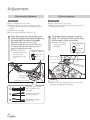
Adjustment ......................................................................... 16
z
Horizontal balance ................................................. 16
z
Stylus pressure ....................................................... 16
z
Anti-skating ............................................................ 17
z
Tone arm height ..................................................... 18
z
Armlift height ......................................................... 19
z
Adjusting the turntable startup/brake speed .......... 19
z
Playing back
Playing records .................................................................... 20
Pitch control (fine adjustment to pitch) ................................ 22
z
Maintenance
Maintenance ....................................................................... 23
Troubleshooting guide ........................................................ 24
Updating the firmware ........................................................ 24
Specifications ...................................................................... 25
Limited Warranty (ONLY FOR U.S.A.) .................................. 26
Limited Warranty (ONLY FOR CANADA) .............................. 27

English
(6)
6
IMPORTANT SAFETY INSTRUCTIONS
Warning
Caution
AC power supply cord
z
The power plug is the disconnecting device.
Install this unit so that the power plug can be
unplugged from the socket outlet immediately.
z
Ensure the earth pin on the power plug is securely
connected to prevent electrical shock.
- An apparatus with CLASS I construction shall be
connected to a power socket outlet with a protective
earthing connection.
Unit
z
To reduce the risk of fire, electric shock or product
damage,
- Do not expose this unit to rain, moisture, dripping or
splashing.
- Do not place objects filled with liquids, such as vases,
on this unit.
- Use only the recommended accessories.
- Do not remove covers.
- Do not repair this unit by yourself.
Refer servicing to qualified service personnel.
Read these operating instructions carefully before using
the unit. Follow the safety instructions on the unit and
the applicable safety instructions listed below.
Keep these operating instructions handy for future
reference.
1 Read these instructions.
2 Keep these instructions.
3 Heed all warnings.
4 Follow all instructions.
5 Do not use this apparatus near water.
6 Clean only with dry cloth.
7 Do not block any ventilation openings. Install in
accordance with the manufacturer’s instructions.
8 Do not install near any heat sources such as
radiators, heat registers, stoves, or other apparatus
(including amplifiers) that produce heat.
9 Do not defeat the safety purpose of the polarized
or grounding-type plug. A polarized plug has two
blades with one wider than the other. A grounding type
plug has two blades and a third grounding prong.
The wide blade or the third prong are provided for your
safety. If the provided plug does not fit into your outlet,
consult an electrician for replacement of the obsolete
outlet.
10 Protect the power cord from being walked on or
pinched particularly at plugs, convenience receptacles,
and the point where they exit from the apparatus.
11 Only use attachments/accessories specified by the
manufacturer.
12 Use only with the cart, stand,
tripod, bracket, or table specified
by the manufacturer, or sold with
the apparatus. When a cart is used,
use caution when moving the cart/
apparatus combination to avoid injury
from tip-over.
13 Unplug this apparatus during lightning storms or when
unused for long periods of time.
14 Refer all servicing to qualified service personnel.
Servicing is required when the apparatus has been
damaged in any way, such as power-supply cord or
plug is damaged, liquid has been spilled or objects
have fallen into the apparatus, the apparatus has
been exposed to rain or moisture, does not operate
normally, or has been dropped.
Unit
z
Do not place sources of naked flames, such as lighted
candles, on this unit.
Placement
z
To reduce the risk of fire, electric shock or product
damage,
- Do not install or place this unit in a bookcase, built-in
cabinet or in another confined space.
Ensure this unit is well ventilated.
- Do not obstruct this unit’s ventilation openings with
newspapers, tablecloths, curtains, and similar items.
z
Keep your speakers at least 10 mm (
13
/
32
”) away from
the system for proper ventilation.

Before use
English
(7)
7
THE FOLLOWING APPLIES ONLY IN THE U.S.A.
FCC Note:
This equipment has been tested and found to comply with
the limits for a Class B digital device, pursuant to Part 15
of the FCC Rules.
These limits are designed to provide reasonable protection
against harmful interference in a residential installation.
This equipment generates, uses and can radiate radio
frequency energy and, if not installed and used in
accordance with the instructions, may cause harmful
interference to radio communications.
However, there is no guarantee that interference will
not occur in a particular installation. If this equipment
does cause harmful interference to radio or television
reception, which can be determined by turning the
equipment off and on, the user is encouraged to try to
correct the interference by one or more of the following
measures:
z
Reorient or relocate the receiving antenna.
z
Increase the separation between the equipment and
receiver.
z
Connect the equipment into an outlet on a circuit
different from that to which the receiver is connected.
z
Consult the dealer or an experienced radio/TV
technician for help.
Any unauthorized changes or modifications to this
equipment would void the user’s authority to operate
this device.
This device complies with Part 15 of the FCC Rules.
Operation is subject to the following two conditions:
(1) This device may not cause harmful interference, and
(2) this device must accept any interference received,
including interference that may cause undesired
operation.
Responsible Party:
Panasonic Corporation of North America
Two Riverfront Plaza, Newark, NJ 07102-5490
Support Contact: http://www.panasonic.com/contactinfo
The following mark and symbols are located on
bottom of the unit.
Conforms to UL STD 60065.
Certified to CAN/CSA STD C22.2 No.60065.
THE FOLLOWING APPLIES ONLY IN CANADA.
CAN ICES-3(B)/NMB-3(B)
Information on Disposal in other
Countries outside the European Union
This symbol is only valid in the European
Union.
If you wish to discard this product, please
contact your local authorities or dealer and
ask for the correct method of disposal.
5
English
IMPORTANT SAFETY INSTRUCTIONS
Read these operating instructions carefully before using the unit. Follow the
safety instructions on the unit and the applicable safety instructions listed
below. Keep these operating instructions handy for future reference.
1 Read these instructions.
2 Keep these instructions.
3 Heed all warnings.
4 Follow all instructions.
5 Do not use this apparatus near water.
6 Clean only with dry cloth.
7 Do not block any ventilation openings. Install in accordance with the
manufacturer’s instructions.
8 Do not install near any heat sources such as radiators, heat registers,
stoves, or other apparatus (including amplifiers) that produce heat.
9 Do not defeat the safety purpose of the polarized or grounding-type plug. A
polarized plug has two blades with one wider than the other. A grounding-
type plug has two blades and a third grounding prong. The wide blade or the
third prong are provided for your safety. If the provided plug does not fit into
your outlet, consult an electrician for replacement of the obsolete outlet.
10 Protect the power cord from being walked on or pinched particularly at plugs,
convenience receptacles, and the point where they exit from the apparatus.
11 Only use attachments/accessories specified by the manufacturer.
12 Use only with the cart, stand, tripod, bracket, or table
specified by the manufacturer, or sold with the apparatus.
When a cart is used, use caution when moving the
cart/apparatus combination to avoid injury from tip-over.
13 Unplug this apparatus during lightning storms or when
unused for long periods of time.
14 Refer all servicing to qualified service personnel.
Servicing is required when the apparatus has been damaged in any way,
such as power-supply cord or plug is damaged, liquid has been spilled or
objects have fallen into the apparatus, the apparatus has been exposed
to rain or moisture, does not operate normally, or has been dropped.
Unit
≥ To reduce the risk of fire, electric shock or product damage,
– Do not expose this unit to rain, moisture, dripping or splashing.
– Do not place objects filled with liquids, such as vases, on this unit.
– Use only the recommended accessories.
– Do not remove covers.
– Do not repair this unit by yourself. Refer servicing to qualified service personnel.
– Do not place heavy items on this unit.
AC power supply cord
≥ The power plug is the disconnecting device.
Install this unit so that the power plug can be unplugged from the socket
outlet immediately.
Unit
≥ Do not place sources of naked flames, such as lighted candles, on this unit.
≥ Do not put any objects on this unit. This unit becomes hot while it is on.
≥ Do not touch the output terminals of the speakers with your hands or other
objects while the speakers are in use. Depending on the conditions of use,
doing so may expose you to high voltage.
Placement
≥ To reduce the risk of fire, electric shock or
product damage,
– Do not install or place this unit in a bookcase,
built-in cabinet or in another confined space.
Ensure this unit is well ventilated.
– Do not obstruct this unit’s ventilation openings
with newspapers, tablecloths, curtains, and
similar items.
≥ More than one person is required to move or
carry the unit.
≥ Ensure that the placement location is sturdy
enough to accommodate the weight of this unit
(> 15).
≥ Do not lift or carry this unit by holding any of its
knobs. Doing so may cause this unit to fall,
resulting in personal injury or malfunction of this
unit.
WARNING
CAUTION
Conforms to UL STD 60065.
Certified to CAN/CSA STD C22.2 No.60065.
THE FOLLOWING APPLIES ONLY IN THE U.S.A.
FCC Note:
This equipment has been tested and found to comply with the limits for a
Class B digital device, pursuant to Part 15 of the FCC Rules.
These limits are designed to provide reasonable protection against harmful
interference in a residential installation. This equipment generates, uses, and
can radiate radio frequency energy and, if not installed and used in accordance
with the instructions, may cause harmful interference to radio communications.
However, there is no guarantee that interference will not occur in a
particular installation. If this equipment does cause harmful interference to
radio or television reception, which can be determined by turning the
equipment off and on, the user is encouraged to try to correct the
interference by one or more of the following measures:
≥ Reorient or relocate the receiving antenna.
≥ Increase the separation between the equipment and receiver.
≥ Connect the equipment into an outlet on a circuit different from that to
which the receiver is connected.
≥ Consult the dealer or an experienced radio/TV technician for help.
FCC Caution: To assure continued compliance, follow the attached
installation instructions and use only shielded interface cables when
connecting to peripheral devices.
Any changes or modifications not expressly approved by the party
responsible for compliance could void the user’s authority to operate this
equipment.
This device complies with Part 15 of the FCC Rules.
Operation is subject to the following two conditions:
(1) This device may not cause harmful interference, and
(2) this device must accept any interference received, including
interference that may cause undesired operation.
Responsible Party:
Panasonic Corporation of North America
Two Riverfront Plaza, Newark, NJ 07102-5490
Support Contact: http://www.panasonic.com/contactinfo
THE FOLLOWING APPLIES ONLY IN CANADA
CAN ICES-3(B)/NMB-3(B)
Information on Disposal in other Countries outside
the European Union
This symbol is only valid in the European Union.
If you wish to discard this product, please contact your local
authorities or dealer and ask for the correct method of disposal.
The lightning flash with arrowhead symbol, within an
equilateral triangle, is intended to alert the user to the
presence of uninsulated “dangerous voltage” within
the product’s enclosure that may be of sufficient
magnitude to constitute a risk of electric shock to persons.
CAUTION
The exclamation point within an equilateral triangle is
intended to alert the user to the presence of important
operating and maintenance (servicing) instructions in
the literature accompanying the appliance.
RISK
OF
ELECTRIC
SHOCK
DO
NOT
OPEN
TO REDUCE THE RISK OF ELECTRIC
SHOCK, DO NOT REMOVE SCREWS.
NO USER-SERVICEABLE PARTS INSIDE.
REFER SERVICING TO QUALIFIED
SERVICE PERSONNEL.
CAUTION :
(5)
SE-R1-SQT0505_PP_mst.book 5 ページ 2015年1月23日 金曜日 午前9時51分

English
(8)
8

Before use
English
(9)
9
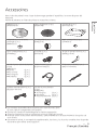
Accessories
In order to prevent damage during shipping some of the equipment has been disassembled.
Please check and identify the supplied accessories.
Turntable (1 pc.)
(RYQ1618-X)
Turntable mat (1 pc.)
(RGS0008)
Dust cover (1 pc.)
(RYF1035-Q)
EP record adaptor (1 pc.)
(RMX0551)
Balance weight (1 pc.)
(RXQ2316)
Auxiliary weight small (1 pc.)
(TPAKK61)
Auxiliary weight big (1 pc.)
(TPAKK62)
Head shell (1 pc.)
(RFA3670)
Overhang gauge (1 pc.)
(RMR2210-W)
Screw set for cartridge (1 set)
(RXQ2315)
z
Nuts (2 pc.)
z
Screws-short (2 pc.)
z
Screws-long (2 pc.)
z
Washers (2 pc.)
PHONO cable (1 pc.)
(K2KYYYY00257)
PHONO earth lead (1 pc.)
(K4EY1YY00160)
AC power supply cord (1 pc.)
(K2CG3YY00191)
Screw set for turntable (1
set
)
(RXQ2343)
z
Screws-long (3 pc.)
z
Washers (3 pc.)
z
Belleville springs (3 pc.)
z
The model numbers of the accessories are as of March 2016.
They are subject to change without notice.
z
Dispose of the packaging materials in an appropriate manner.
z
Follow the local regulations when disposing of the product.
z
Do not use any other AC power supply cord, PHONO cable and PHONO earth lead except the
supplied one.
z
Keep the cartridge, auxiliary weight, nuts, screws and washers out of reach of children to prevent
swallowing.

English
(10)
10
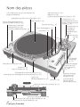
Parts Name
Balance weight
(
13)
Stylus pressure
control (
16)
Arm lock
(
18)
Arm-height
control ring
(
18)
Anti-
skating
control
(
17)
Pitch range select
button (
22)
Arm clamp (
16)
Arm rest (
16)
Cue lever (
16)
Speed select buttons (
20)
Turntable (
12)
Turntable mat (
12)
Stylus light (
21)
Stylus light switch (
21)
EP record adaptor (
20)
Center spindle (
12)
Insulator (
15)
START-STOP button (
20)
ON/OFF (power) (
20)
Strobo light (
22)
RESET button (
21)
PITCH ADJ control
(
22)
Auxiliary
weight
mounting
location (
13)
Head shell (
11)
Locking nut (
13)
Tone arm (
13)
PHONO earth terminal (
14)
AC input terminal (
14)
Dust cover fitting part (
15)
PHONO output terminal (
14)
Back
Numbers such as (
20) indicate reference pages.

Before use Getting started
English
(11)
11
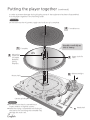
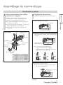
Putting the player together
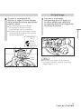
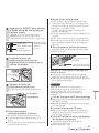
1
Attach a cartridge (store-bought)
tentatively.
Follow the cartridge’s instructions to
correctly attach it to the head shell, and
tighten the screws lightly.
z
If the mounting screws are included in
the cartridge, use them.
z
When playing SP records, use a cartridge
for SP records.
z
Use a commercially available mini flat
screwdriver (4 mm
[
5
/
32
”
]
).
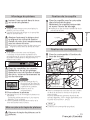
Attaching the cartridge
Fit the overhang gauge to the head shell.
l
Tighten the screw for cartridge.
The overhang can be adjusted optimally.
Screw for
cartridge
Overhang gauge
Head
shell
Head shell
Lead wire
Cartridge
Stylus
(Lead wire) (Terminal)
Red
R+ (Red)
Green
R- (Green)
White
L+ (White)
Blue
L- (Blue)
Screw for cartridge
Terminal
(Example)
52 mm
2
Adjust the overhang.
Use the included overhang gauge.
k
Move the cartridge to line the stylus tip up
with the end of the gauge.
z
The cartridge should be parallel on
the shell head when viewed from the
top and side (the illustration is the top
view).
z
Be careful not to allow the cartridge to
slip out of place.
Stylus tip
(2-3/64“)
Nuts
Washers

English
(12)
12
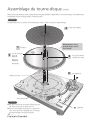
Putting the player together
(continued)
In order to prevent damage during shipping some of the equipment has been disassembled.
Put the player together in the following order.
Do not connect the AC power supply cord until set up is complete.
Attention
Turntable mat
Turntable
Center spindle
Rotor shaft
Balance weight
Head shell
Handle carefully as
this is heavy.
6
4
1
3
Mounting
screw for
turntable
Belleville
spring
Washers
Rotor shaft fix
hole
2
Attention
z
Do not use an electric screwdriver or
impact wrench to tighten screws.
z
Note that using a screwdriver not fitting to
the screws for mounting the turntable may
damage the main unit.
5

Getting started
English
(13)
13
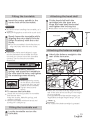
Fitting the turntable
1
Insert the center spindle in the
center hole of the turntable.
Attention
z
Be careful when handling the turntable, as it
is heavy.
z
Wipe off fingerprints or dirt with a soft cloth.
2
Slowly lower the turntable while
aligning the rotor shaft fix holes
(three locations) with the rotor
shafts.
z
Turn the turntable in both directions to
align the holes with the rotor shafts.
Attention
z
If the rotor shafts are misaligned, a gap
remains between the turntable and main
unit and you cannot mount the turntable
correctly. Do not force the turntable
downward.
3
Attach the washers, belleville
springs, and screws for turntable to
the rotor shaft fix holes, and tighten
the mounting screws securely.
To remove the turntable
Loosen the mounting screws for turntable
and remove them.
- Keep the screws, belleville springs, and
washers carefully.
k
Hold the turntable with both hands and
slowly pull it straight up.
Fitting the turntable mat
4
Lay the turntable mat on the
turntable.
Attention
z
When tightening screws,
do not allow screw heads
to protrude from the top
surface of the turntable.
z
Tighten three screws
evenly.
Attaching the head shell
5
Fit the head shell with the
cartridge into the tone arm.
Keep the head shell horizontal
and tighten the locking nut.
z
Be careful not to touch the stylus tip.
Locking nut
Head shell
Attaching the balance weight
6
Attach the balance weight to the
rear of the tone arm.
Balance weight
Auxiliary weight
z
The inside of the balance weight is greased.
Note
z
Attach the included auxiliary weight to the
rear of the tone arm according to the weight
of your cartridge.
For adjustable cartridge weight ranges, see
"Applicable cartridge weight range". (
25)

English
(14)
14
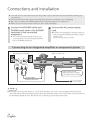
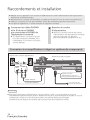
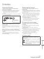
Connecting to an integrated amplifier or component system
Connections and installation
z
Turn off all units and disconnect the AC power supply cord from the outlet before making any
connections.
z
Connect the AC power supply cord only after all other connections are completed.
z
Be sure to connect the PHONO earth lead. Otherwise mains hum may occur.
z
Refer also to the instruction manual of the connected device.
1
Connect the PHONO cables and
PHONO earth lead to the PHONO
terminals of the connected
equipment.
z
You will not have adequate volume or
sound quality if the connected amplifier
has no PHONO terminals.
2
Connect the AC power supply
cord.
z
Confirm the wattage of the AC outlet on
the connected equipment before using it
for this unit.
(This unit consumes 14 W.)
z
Although the AC power switch is in the "OFF" position, the unit is not completely disconnected
from the mains. Remove the plug from the main electrical outlet if you will not be using the unit for
an extended period of time. Place the unit so the plug can be easily removed.
Note
Amplifier(not included)
PHONO
PHONO
LR
LR
Insert the AC power
supply cord up to a point
just before the round hole.
Back of main unit
To a household
mains socket

Getting started
English
(15)
15
Installation
Install the unit on a horizontal surface
protected from vibrations.
Keep this unit as far as possible from speakers.
Adjusting the height to make the
unit horizontal
Raise the main unit to turn the insulators and
adjust the height.
z
Clockwise: Reduces the height.
z
Anti-clockwise: Increases the height.
Attention
z
Do not turn the insulators too far.
Doing so may cause them to come off or
damage them.
Notes for installation
z
Before you move the unit, remove all devices
connected and turn off the power supply.
z
Ensure the unit is not exposed to direct
sunlight, dust, humidity, and heat from a
heating appliance.
z
This unit may pick up interference from a
radio if there is one nearby.
Keep the unit as far as possible from a radio.
z
Do not install the unit on a heat source.
z
Avoid a place with large temperature variations.
z
Avoid a place with frequent condensation.
z
Avoid an unstable place.
z
Do not put an object on the unit.
z
Do not install the unit in a confined space
such as a book shelf.
z
Install the unit at a position well away from
walls or other devices to ensure effective
heat radiation from the inside of the unit.
z
Make sure that the material of the
installation location is sufficiently strong to
withstand the weight of this unit.
z
Note that the unit may be damaged by
cigarette smoke or moisture from an
ultrasonic humidifier.
Condensation
Think of taking out a cold bottle from a
refrigerator. If you leave it in a room for a while,
dewdrops will form on the bottle surface. This
phenomenon is called “condensation“.
z
Conditions causing condensation
Rapid temperature change (caused by
moving from a warm place to a cold place or
vice versa, rapid cooling or heating, or direct
exposure to cooled air)
High humidity in a room with much steam,
etc.
Rainy season
z
Condensation may damage the unit. If it
has occurred, turn the unit off and leave it
until it adapts to the ambient temperature
(approximately 2 to 3 hours).
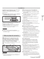
Fit the dust cover
1
Hold the dust cover with both
hands and insert it into the dust
cover fitting parts (
10) on the
player.
z
To remove the dust cover, keep it open
and lift it straight above.
Attention
z
Return the tone arm to the arm rest and fix
it with the arm clamp before you attach or
detach the dust cover.

English
(16)
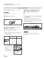
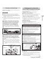
1
Turn the stylus pressure control
until “0“ comes to the center line
of the rear of the tone arm.
z
Hold the balance
weight still while
doing this.
Preparation
z
First, remove the dust cover.
z
Return the tone arm to the arm rest and fix it
with the arm clamp.
Stylus pressure
Adjustment
Balance weight
Arm clamp
Center line
Stylus pressure
control
Hold here
to turn
Note
16
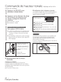
Anti-skating control
Arm clamp
Arm rest
Cue lever
1
Free the tone arm from the arm
rest and adjust horizontal balance
by turning the balance weight.
Hold the tone arm and turn the
balance weight in the arrow direction
to adjust the balance until the arm is
approximately horizontal.
z
Take care not to
allow the stylus tip
to touch the
turntable or main
unit.
Balance weight
Hold here
to turn
Horizontal balance
Preparation
z
First, remove the dust cover.
z
Remove the stylus cover, taking care not
to damage the stylus, then release the arm
clamp.
z
Lower the cue lever.
z
Turn the anti-skating control to “0”.
Balanced and the tone
arm is parallel to the
turntable.
The balance weight is
too far forward.
The balance weight is
too far back.
z
Refer to the user's guide for your stylus for
the appropriate stylus pressure.

Getting started
English
(17)
Anti-skating
1
Turn the anti-skating control to
adjust it to the same value as the
stylus pressure control.
2
Turn the balance weight to adjust
to the appropriate stylus pressure
for the cartridge.
z
The stylus pressure control will turn
together with the balance weight.
z
Turn until the center line points to the
appropriate stylus pressure.
Center line
Balance weight
Hold here
to turn
Turns
together
17
z
For stylus pressures 3
g
and above, adjust
anti-skating control to "3".
Note

English
(18)
Adjustment
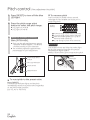
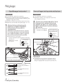
(continued)
Tone arm height
Make this adjustment only if the cartridge you
are using makes it necessary.
Preparation
z
Put a record on the turntable.
1
Release the arm lock.
Index line
Arm-height control
ring
Cartridge height
(H) in millimeters
Height control
position
17
18
19
20
21
22
23
0
1
2
3
4
5
6
Arm lock
(Released)
(Locked)
Use the chart below as reference to find the
appropriate position mark for the height of
your cartridge.
k
Turn the arm-height
control ring to align the
position mark with the
index line.
0 to 6 mm (0” to
15
/
64
”)
are marked on the arm
height control ring.
2
Adjust the height with the arm-
height control ring.
Adjust the arm height until the tone arm
becomes parallel to a record.
(For supplied head shell)
When you don't know the cartridge
height (H),
Remove the stylus cover, taking care not to
damage the stylus, then release the arm clamp.
Lower the cue lever, rest the stylus on a record
and adjust the height control until the tone arm
and record are parallel.
3
After arm height adjustment is
finished, lock the tone arm by
turning the arm lock knob.
Parallel to the turntable
Attention
z
Be careful not to damage the stylus tip.
z
Do not use the product with the arm lock
released.
18

Getting started
English
(19)
19
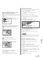
Armlift height
Make an adjustment according to your
cartridge if necessary.
Preparation
z
Put a record on the turntable.
z
Remove the stylus cover, taking care not
to damage the stylus, then release the arm
clamp.
z
Lift the cue lever and move the tone arm over
the record.
1
Check the armlift height (distance
between the stylus tip and record
surface).
If adjustment is needed, go to the
step
2
.
z
The armlift height is factory-adjusted to
8 to 13 mm
(
5
/
16
” to
33
/
64
”)
.
2
Return the tone arm to the arm
rest and fix it with the arm clamp.
Turn the adjustment screw.
z
Turning the screw clockwise lowers the
armlift.
z
Turning the screw anti-clockwise raises
the armlift.
Armlift
screw
Armlift
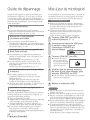
You can choose manual mode or auto mode.
(Factory setting: Auto mode)
Auto mode
We recommend auto mode that can maximize
performance of the product. It adjusts the
"startup speed" (described below) automatically.
(The set torque control is not reflected.)
Move the mode switch to [A] using a tool
such as a thin screwdriver.
Manual mode
Allows you to adjust the "startup speed" manually.
Move the mode switch to [M] using a tool
such as a thin screwdriver.
Startup speed
You can adjust the startup speed (the time for
the turntable to reach the constant speed) from
pressing [START-STOP] and the torque gain at
the constant speed.
Adjust the torque knob using a flat
screwdriver.
z
H direction: Fast startup
z
L direction: Slow startup
Brake speed
You can adjust the brake speed from pressing
[START-STOP] until the turntable stops.
(Adjustment is possible in both auto and
manual mode.)
Adjust the brake speed control knob using a
flat screwdriver.
z
S direction: Slow stop
z
F direction: Fast stop
S
BRAKE
TORQUE
F
H
L
M
A
Brake speed
control knob
Torque knob
Mode switch
Adjusting the turntable startup/
brake speed
Note
z
Use a commercially available mini flat
screwdriver (2.4 mm
[
3
/
32
”
]
) to adjust the
torque/brake speed control knob.
z
Do not turn the knob too far using an
excessive force.
19

English
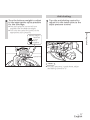
(20)
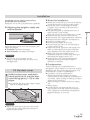
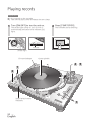
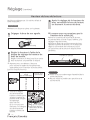
Playing records
1
Turn [ON/OFF] to turn the unit on.
The strobo light comes on. 33-1/3 r/min is
automatically selected and the indicator [33]
lights.
2
Press [START-STOP].
The turntable starts revolving.
Speed select buttons
Indicators
·
4
3
5
1
2
EP record adaptor
Center spindle
1
2
2
Preparation
1 Put a record on the turntable.
2 Take off the stylus cover and release the arm clamp.
33 45
78
START・STOP
33
・
・
・
+6.4
3.3
0
-
3.3
%
Strobo light
Indicator
20
La page est en cours de chargement...
La page est en cours de chargement...
La page est en cours de chargement...
La page est en cours de chargement...
La page est en cours de chargement...
La page est en cours de chargement...
La page est en cours de chargement...
La page est en cours de chargement...
La page est en cours de chargement...
La page est en cours de chargement...
La page est en cours de chargement...
La page est en cours de chargement...
La page est en cours de chargement...
La page est en cours de chargement...
La page est en cours de chargement...
La page est en cours de chargement...
La page est en cours de chargement...
La page est en cours de chargement...
La page est en cours de chargement...
La page est en cours de chargement...
La page est en cours de chargement...
La page est en cours de chargement...
La page est en cours de chargement...
La page est en cours de chargement...
La page est en cours de chargement...
La page est en cours de chargement...
La page est en cours de chargement...
La page est en cours de chargement...
La page est en cours de chargement...
La page est en cours de chargement...
La page est en cours de chargement...
La page est en cours de chargement...
-
 1
1
-
 2
2
-
 3
3
-
 4
4
-
 5
5
-
 6
6
-
 7
7
-
 8
8
-
 9
9
-
 10
10
-
 11
11
-
 12
12
-
 13
13
-
 14
14
-
 15
15
-
 16
16
-
 17
17
-
 18
18
-
 19
19
-
 20
20
-
 21
21
-
 22
22
-
 23
23
-
 24
24
-
 25
25
-
 26
26
-
 27
27
-
 28
28
-
 29
29
-
 30
30
-
 31
31
-
 32
32
-
 33
33
-
 34
34
-
 35
35
-
 36
36
-
 37
37
-
 38
38
-
 39
39
-
 40
40
-
 41
41
-
 42
42
-
 43
43
-
 44
44
-
 45
45
-
 46
46
-
 47
47
-
 48
48
-
 49
49
-
 50
50
-
 51
51
-
 52
52


Technics SL1210GREGK Le manuel du propriétaire
- Catégorie
- Équipement musical supplémentaire
- Taper
- Le manuel du propriétaire
- Ce manuel convient également à
dans d''autres langues
- English: Technics SL1210GREGK Owner's manual
Documents connexes
Autres documents
-
Panasonic Digital Wireless Stereo Headphones Mode d'emploi
-
Denon DP-300F Le manuel du propriétaire
-
Yamaha P-450 Le manuel du propriétaire
-
TEAC TN-350 Le manuel du propriétaire
-
-
Pioneer PLX-500-W Manuel utilisateur
-
Panasonic EAHTZ700E Mode d'emploi
-
Panasonic RBM300BE Manuel utilisateur
-
Panasonic SL1200GAEEG Le manuel du propriétaire
-
Panasonic SL1210M5G Le manuel du propriétaire