US Water Stenner Series SVP Manuel utilisateur
- Taper
- Manuel utilisateur

SVP Series
INSTALLATION AND
MAINTENANCE MANUAL
Metering Pumps
Manufactured Since 1957

www.stenner.com2
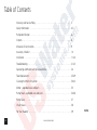
Table of Contents
Warranty and Service Policy . . . . . . . . . . . . . . . . . . . . . . . . . . . . . . . . . . . . . . . . 3
Safety Information . . . . . . . . . . . . . . . . . . . . . . . . . . . . . . . . . . . . . . . . . . . . . . . 4-5
Pump Identification . . . . . . . . . . . . . . . . . . . . . . . . . . . . . . . . . . . . . . . . . . . . . . 6-7
Outputs . . . . . . . . . . . . . . . . . . . . . . . . . . . . . . . . . . . . . . . . . . . . . . . . . . . . . . . 8
Materials of Construction . . . . . . . . . . . . . . . . . . . . . . . . . . . . . . . . . . . . . . . . . . 9
Accessory Checklist . . . . . . . . . . . . . . . . . . . . . . . . . . . . . . . . . . . . . . . . . . . . . . 10
Installation . . . . . . . . . . . . . . . . . . . . . . . . . . . . . . . . . . . . . . . . . . . . . . . . . . . . . 11-20
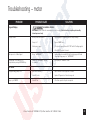
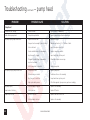
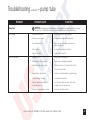
Troubleshooting . . . . . . . . . . . . . . . . . . . . . . . . . . . . . . . . . . . . . . . . . . . . . . . . . 21-23
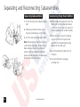
Separating and Reconnecting Subassemblies . . . . . . . . . . . . . . . . . . . . . . . . . . . 24
Tube Replacement . . . . . . . . . . . . . . . . . . . . . . . . . . . . . . . . . . . . . . . . . . . . . . . 25-29
Cleaning the Point of Injection . . . . . . . . . . . . . . . . . . . . . . . . . . . . . . . . . . . . . . 30-32
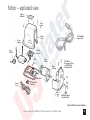
Motor – exploded view and parts . . . . . . . . . . . . . . . . . . . . . . . . . . . . . . . . . . . 33
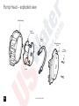
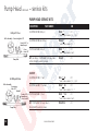
Pump Head – exploded view and parts . . . . . . . . . . . . . . . . . . . . . . . . . . . . . . . 34-36
Pump Tubes . . . . . . . . . . . . . . . . . . . . . . . . . . . . . . . . . . . . . . . . . . . . . . . . . . . . 37
Check Valves . . . . . . . . . . . . . . . . . . . . . . . . . . . . . . . . . . . . . . . . . . . . . . . . . . . 38
For Your Records . . . . . . . . . . . . . . . . . . . . . . . . . . . . . . . . . . . . . . . . . . . . . . . . 39
SVP06

US and Canada call 1.800.683.2378, other countries call 1.904.641.1666
3
Damaged or Lost Shipments
UPS and prepaid truck shipments: Check your order
immediately upon arrival. All damage must be noted on
the delivery r
eceipt. Call Stenner Customer Service at
800.683.2378 for all shortages and damages within
seven (7) days of receipt.
Returns
Stenner offers a 30-day return policy on factory direct
pur
chases. Except as otherwise provided, no material
will be accepted for return after 30 days from purchase.
To return merchandise at any time, call Stenner at
800.683.2378 for a Returned Goods Authorization
(RGA) number. A 15% re-stocking fee will be applied.
Include a copy of your invoice or packing slip with
your return.
Limited Warranty
Stenner Pump Company will for a period of one (1) year
f
rom the date of purchase (proof of purchase required)
repair or replace – at our option – all defective parts.
Stenner Pump Company is not responsible for any
removal or installation costs. Pump tube assemblies and
rubber components are considered perishable and
are not covered in this warranty. Pump tube will be
replaced each time a pump is in for service, unless
otherwise specified. The cost of the pump tube
replacement will be the responsibility of the customer.
Stenner Pump Company will incur shipping costs
for warranty products shipped from our factory in
Jacksonville, Florida. Any tampering with major
components, chemical damage, faulty wiring, weather
conditions, water damage, power surges, or products
not used with reasonable care and maintained in
accordance with the instructions will void the warranty.
Stenner Pump Company limits its liability solely to the
cost of the original product. We make no other warranty
expressed or implied.
Disclaimer
The information contained in this manual is not
intended for specific application purposes. Stenner
Pump Company r
eserves the right to make changes
to prices, products, and specifications at any time
without prior notice.
Warranty and Service Policy

www.stenner.com4
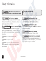
Safety Information
ELECTRIC SHOCK HAZARD:
Pump supplied with grounding power cord and attached plug.
To reduce risk of electrical shock, connect only to a properly
grounded, grounding type receptacle.
RISQUE DE CHOC ELECTRIQUE:
Cette pompe est équipée d’une fiche de mise à terre. Pour
réduire le risque de choc électrique, s’assurer que la fiche est
bien raccordée à une prise de courant avec une connexion de
mise à terre.
DO NOT alter the power cord or plug end.
DO NOT use receptacle adapters.
DO NOT use pump with a damaged or altered power
cord or plug. Contact the factory or an authorized service
facility for repair
.
HAZARDOUS VOLTAGE:
DISCONNECT power cord before removing motor cover for
service. Electrical service by trained personnel only.
EXPLOSION HAZARD:
This pump IS NOT explosion proof. DO NOT install or operate in
an explosive environment.
RISK OF FIRE HAZARD:
DO NOT install or operate on any flammable surface.
RISK OF CHEMICAL EXPOSURE:
Potential for chemical burns, fire, explosion, personal injury, or
property damage. To reduce risk of exposure, the use of proper
personal protective equipment is mandatory.
AVERTISSEMENT
Warns about hazards that CAN cause
death, serious personal injury, or property damage if ignored.
ELECTRIC SHOCK HAZARD

US and Canada call 1.800.683.2378, other countries call 1.904.641.1666 5
Safety Information continued
Warns about hazards that WILL or CAN
cause minor personal injury or property damage if ignored.
NOTICE: Indicates special instructions or general
mandatory action.
NOTICE: This metering pump and its components have
been tested for use with the following chemicals: Sodium
Hypochlorite (10-15%), Muriatic Acid (20-22 BAUME,
31.5% Hcl), and Soda Ash.
NOTE: Cette a pompe de dosage et ses composants ont
été testés pour utilisation avec les produits chimiques
suivants; Hypochlorite de Sodium (solution de 10-15%);
Acide Muriatique (20-22 Baume, 31.5% Hcl); Cendre
de Soude.
NOTICE: This metering pump is portable and designed
to be removable from the plumbing system without
damage to the connections.
This is the safety alert symbol. When displayed in
this manual or on the equipment, look for one of the
following signal words alerting you to the potential for
personal injury or property damage.
PUMP INTENDED FOR INDOOR USE.
Cette pompe est prévue pour utilisation à l’intérieur.
Electrical installation should adher
e to all national and local
codes. Consult a licensed professional for assistance with proper
electrical installation.
Pump uses a class 2 auto switching power supply for AC
input voltage rated 100-240VAC.

www.stenner.com6
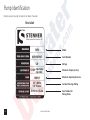
Pump Identification
Model
Serial Number
Maximum Output per Day
Suction/Discharge Tubing
Item Number for
Placing Order
Voltage
Identify your pump using the label on the box or the pump.
SVP4
02010503945
120
5/18.9
Adjustable
5/18.9 Ajustable
100/6.9
1/4" White
1/4" Blanco
SVP4H1A1SUAA
Box Label
5/18.9
Maximum Operating Pressure

US and Canada call 1.800.683.2378, other countries call 1.904.641.1666 7
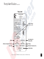
Pump Identification continued
Item Number for
Placing Or
der
Voltage
Maximum Output per Day
SVP4
SVP4H1A1SUAA
100 psi / 6.9 bar
120VAC / 60Hz
1.5 amp
5 GPD / 18.9 LPD
02010503945
Pump Label
Model
Maximum Operating Pressure
Agency Listings
(varies by model)
Serial Number
Amp Draw
STENNER PUMP COMPANY

www.stenner.com8
Variable Speed Maximum Pump Tube range gallons range liters range gallons range liters range ounces range milliliters
Series Pressure Number per day per day per hour per hour per minute per minute
Variable Speed
SVP1* 100 psi/6.9 bar #1
SVP1 25 psi/1.7 bar #1
w/4-20mA Input
SVP4* 100 psi/6.9 bar
SVP4 25 psi/1.7 bar
Variable Speed
SVP1* 100 psi/6.9 bar
SVP1 25 psi/1.7 bar
w/4-20mA Input
SVP4* 100 psi/6.9 bar
SVP4 25 psi/1.7 bar
Variable Speed
SVP1* 100 psi/6.9 bar
w/4-20mA Input
SVP4* 100 psi/6.9 bar
Variable Speed
SVP1 25 psi/1.7 bar
w/4-20mA Input
SVP4 25 psi/1.7 bar
Variable Speed
SVP1 25 psi/1.7 bar
w/4-20mA Input
SVP4 25 psi/1.7 bar
Variable Speed
SVP1 25 psi/1.7 bar
w/4-20mA Input
SVP4 25 psi/1.7 bar
Approx. Outputs @ 50 & 60 Hz
#1
#2
#3
#4
#7
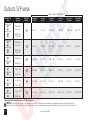
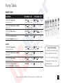
0.3 to 5.0 1.1 to 18.9 0.01 to 0.21 0.05 to 0.79 0.03 to 0.44 0.76 to 13.13
0.8 to 17.0 3.0 to 64.4 0.03 to 0.71 0.13 to 2.68 0.07 to 1.51 2.08 to 44.65
2.0 to 40.0 7.6 to 151.4 0.08 to 1.67 0.32 to 6.31 0.18 to 3.55 5.27 to 105.14
2.0 to 40.0 7.6 to 151.4 0.08 to 1.67 0.32 to 6.31 0.18 to 3.55 5.27 to 105.14
#5
3.0 to 60.0 11.4 to 227.1 0.13 to 2.5 0.48 to 9.46 0.27 to 5.33 7.92 to 157.71
4.3 to 85.0 16.3 to 321.8 0.18 to 3.54 0.68 to 13.40 0.38 to 7.55 11.32 to 223.40
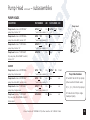
Outputs SVP series
NOTICE: The information within this chart is solely intended for use as a guide. The output data is an approximation based on pumping water under a controlled testing environment.
Many variables can affect the output of the pump. Stenner Pump Company recommends that all metering pumps undergo field calibration by means of analytical testing to confirm their outputs.
*pump supplied with injection check valve for 26-100 psi applications

US and Canada call 1.800.683.2378, other countries call 1.904.641.1666 9
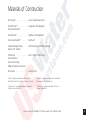
Materials of Construction
All Housings* . . . . . . . . . . . . . . . . . Lexan
®
Polycarbonate Plastic
Peristaltic Tube** . . . . . . . . . . . . . . Santoprene
®
FDA Approved
Check Valve Duckbill
Peristaltic Tube
†
. . . . . . . . . . . . . . . Tygothane
®
FDA Approved
Check Valve Duckbill
††
. . . . . . . . . . Pellathane
®
Suction/Discharge Tubing . . . . . . . . LDPE Polyethylene-NSF/FDA Approved
Ferrules (1/4" & 6mm)
Tube Fittings . . . . . . . . . . . . . . . . . Type 1 Rigid PVC-NSF Listed
Connecting Nuts
Check Valve Fittings
Weighted Suction Line Strainer
All Fasteners . . . . . . . . . . . . . . . . . Stainless Steel
*Lexan
®
is a registered trademark of General Electric.
Consult General Electric for chemical resistance of Lexan
®
.
**Santoprene
®
is a registered trademark of Advanced
Elastomer System, Akron, OH.
†
Tygothane
®
is a registered trademark of Saint-Gobain
Performance Plastics, Pittsburgh, PA.
††
Pellathane
®
is a registered trademark of The Dow
Company, Midland, MI.

www.stenner.com10
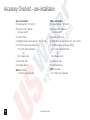
25 psi unit includes:
(3) Connecting Nuts (1/4" or 3/8")
(3) Ferrules w/1/4" & 6mm or
(2) Ferrules w/3/8"
(1) Injection Fitting
(1) W
eighted Suction Line Strainer 1/4", 3/8", or 6mm
(1) 20' Roll of Suction & Discharge Tubing
1/4" or 3/8" white or UV black
OR
6mm (Europe) white
(1) Spare Pump Tube
(1) Installation Manual
SVP4 also includes:
(1) 4-20mA input signal cor
d
100 psi unit includes:
(3) Connecting Nuts (1/4" or 3/8")
(3) Ferrules w/1/4" & 6mm or
(2) Ferrules w/3/8"
(1) Injection Check V
alve
(1) Weighted Suction Line Strainer 1/4", 3/8", or 6mm
(1) 20' Roll of Suction & Discharge Tubing
1/4" or 3/8" white or UV black
OR
6mm (Europe) white
(1) Spare Pump Tube
(1) Installation Manual
SVP4 also includes:
(1) 4-20mA input signal cord
Accessory Checklist – pre-installation

US and Canada call 1.800.683.2378, other countries call 1.904.641.1666 11
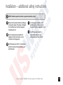
Installation – additional safety instructions
Read all safety hazards before installing or
servicing the pump. The pump is designed
for installation and service by properly
trained personnel.
Use all required personal protective
equipment when working on or near
a chemical metering pump.
Install the pump so that it is in compliance
with all national and local plumbing and
electrical codes.
Use the proper product to treat
potable water systems, use only
chemicals listed or approved for use.
Install the pump to work in
conjunction with pool, spa,
well pump, or system controls.
NOTICE: Indicates special instructions or general mandatory action.

www.stenner.com12
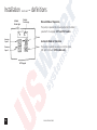
Installation continued – definitions
Manual Mode of Operation
The pump is operated by manually adjusting the motor
speed with the keypad. SVP1 and SVP models.
Automatic Mode of Operation
The pump is paced by an external 4-20mA signal,
LED light illuminate. SVP4 models only.
4-20mA
Mode Light
Increase
Speed
Decrease
Speed
Output
Percentage
Power
Prime
SVP Keypad

US and Canada call 1.800.683.2378, other countries call 1.904.641.1666 13
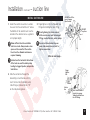
Select mounting surface.
Select a dry location (to avoid water
intrusion and pump damage) above the
solution tank.
To prevent pump damage in the event of
a pump tube leak, never mount the pump
vertically with the pump head up.
To avoid chemical damage from fumes,
do not mount pump directly over an
open solution tank. Keep tank covered.
Avoid flooded suction or pump mounted
lower than the solution container.
Draw solution from the top of the tank.
If pump is installed with a flooded
suction, a shut-off valve or other device
must be provided to stop flow to pump
during service.
Do not allow water intrusion into the
motor or corrosion and damage will occur.
Installation continued – mount pump
MOUNT PUMP

www.stenner.com14
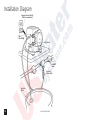
Grounded Power Outlet
(GFIC recommended)
Out
(Discharge)
In (Suction)
Shut-Off
Valve
Injection
Check Valve
Solution
Tank
Installation Diagram

US and Canada call 1.800.683.2378, other countries call 1.904.641.1666 15
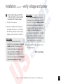
Installation continued – verify voltage and power
To prevent motor damage, verify with
a volt meter that the receptacle voltage
corresponds with the pump voltage.
1. Plug cord into receptacle.
2. Depress the ON/OFF button located on
the keypad to verify the unit is tur
ned on.
Red LED display will light up when supply
voltage is present and unit is turned ON.
SVP1 models:
The SVP1 does not have 4-20mA
capabilities and only operates in manual
mode of operation. The output can be
incremented thr
ough its available speed
range by utilizing the UP/DOWN keys on
the keypad. Depress the ON/OFF button
once again to turn the pump off. Proceed
to t
he Install Suction Line steps.
SVP4 models:
In the manual mode of operation, the
metering pump functions identically to
the SVP1. To change to automatic mode
of operation, simultaneously depress both
the UP and DOWN keys and h
old for two
seconds. The mode of operation will
change and be indicated by a small LED
light located at the left side of the
display. Any settings entered in the variable
speed mode will remain in memory.
3. Depress ON/OFF button again to turn the
metering pump off.
More on next page…

www.stenner.com16
Installation continued – verify voltage and power
RISK OF EQUIPMENT MALFUNCTION
OR DAMAGE:
DO NOT connect input signal cord to any AC electrical supply.
DO NOT exceed 48VDC input signal.
Pump is not a sour
ce or power supply for the 4-20mA signal
loop. Refer to input signal specifications.
Pump and input signal must be “OFF” prior to connecting input
signal. Failure to follow this war
ning may result in microcontroller
corruption and erratic operation.
Failure to connect input signal with proper polarity will result in
the pump not responding to the input signal.
The LED display can vary if the pump is exposed to a 9-30MHz
signal when operating in the “automatic” mode.
RISQUE DE DEFAUT DE
FONCTIONNEMENT OU DE
DOMMAGES A L’EQUIPEMENT:
NE JAMAIS connecter le cordon du signal d’entrée à n’importe
quelle sour
ce de courant alternatif.
Ne pas excéder le signal d’entrée 48VDC.
La pompe n’est pas une source ni une alimentation en courant
pour la boucle de signal 4 à 20mA. Consulter les spécifications
du signal d’entrée.
Mettre sur Arrêt (“OFF”) la pompe et le signal d’entr
ée, avant
d’effectuer la connexion du cordon du signal d’entrée. Si cette
précaution n’est pas prise, la micro-contrôleur risque d’être
corrompu et le fonctionnement irrégulier.
Si le signal d’entrée n’est pas connecté à la polarité appropriée,
la pompe ne réagira pas à ce signal.
L’afficheur LED peut varier si la pompe est exposée à un signal
9-30MHz en fonctionnant en mode “automatique.”
SVP4 models:
If using the automatic mode of operation (4-20mA DC analog
signal), plug the input signal connector (gray jacketed 6' cable)
to the receptacle located on the front of the pump beneath
the pump head. Connect the jacketed cable to the supply
conductor (4-20mA source) ensuring proper polarity. Red is
positive, black is negative.
AVERTISSEMENT

US and Canada call 1.800.683.2378, other countries call 1.904.641.1666 17
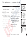
1. Uncoil the suction line and cut a section
to assure that the end will be 2-3" above
the bottom of the solution tank. Use the
outside of the solution tank as a guide to
cut to proper length.
Allow sufficient slack to avoid kinks
and stress cracks. Always make a clean
square cut to assure that the suction
line is burr free. Normal maintenance
requires trimming.
Suction lines that extend to the bottom
of the tank can result in debris pickup
leading to clogged injectors and possible
tube failure.
2. Slide the suction line through the
connecting nut and ferrule and fully
insert the line into the bottom pump
tube fitting as indicated by the “IN”
on the tube housing cover
.
3. Finger tighten nut to the threaded tube
fitting while holding the tube fitting.
Over tightening the ferrule and nut
with a wrench may result in damaged
fittings, crushed ferrules, and air pickup.
Do not use thread sealant tape on
pump tube connections or tools to
tighten connections.
Installation continued – suction line
DO NOT use Teflon
tape on pump
tube threads.
DO NOT
use pliers.
More on next page…
INOUT
Suction
line
Ferrules
Finger
tighten
nut
Note: Beveled ends of
ferrules face pump.
Tubing should bottom
into all fittings.
INSTALL SUCTION LINE

www.stenner.com18
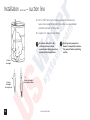
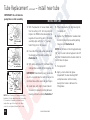
Strainer
w/weight
Strainer w/weight
(disassembled view)
Strainer
w/weight
(closeup view)
4. Drill a 17/64" hole into the lid or bung cap of the solution tank.
Secure strainer weight to the end of the suction line as per provided
instructions and feed it into the hole.
5. Suspend 2-3" above the tank bottom.
Installation continued – suction line
Do not mix chemicals in the
solution container. Follow
recommended mixing procedures
according to the manufacturer.
Do not operate pump unless
chemical is completely in solution.
Turn pump off when replenishing
solution.

US and Canada call 1.800.683.2378, other countries call 1.904.641.1666 19
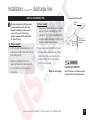
Installation continued – discharge line
HAZARDOUS PRESSURE:
Shut off water or circulation system
and bleed off any system pressure.
1/4'' or 1/2''
FNPT Reduction
Bushing
Injection
Check
Valve
Shut-Off
V
alve
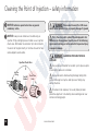
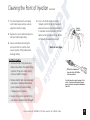
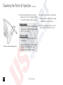
Typical Point of Injection
The injection point and fitting require
periodic maintenance to clean any
deposits or buildup. To allow quick
access to the point of injection,
Stenner recommends the installation
of shut-off valves.
26-100 psi models:
• Prior to making tubing connection, test
check valve and NPT threads for leaks by
pressurizing system.
• Tighten an additional 1/4 turn if
necessary. Make final tube connection
as instructed in Install Suction Line
instructions.
0-25 psi models:
Low-pressure models do not have a check
valve and check valve body. Insert the
tubing 3/4" to 1" into the injection fitting
and make tubing connection as instructed
in Install Suction Line instructions.
1. Depress and hold the PRIME button on
the keypad and allow the pump to fully
prime. The Prime key will operate the
pump at 100% but will not display
100% on the keypad.
More on next page…
INSTALL DISCHARGE LINE

www.stenner.com20
Installation continued – discharge line
SVP1 models:
Use the manual mode of operation to set the metering pump
to the desired speed required for the application. This is the
initial setting. Check the entire system for leaks. Proceed to
Step 2.
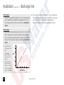
SVP4 models:
For automatic mode of operation, verify that the 4-20mA LED
light is displayed on the keypad. Provide the required signal
for the automatic mode of operation. The pump will respond
to the 4-20mA input signal and pace accordingly. Proceed to
Step 2.
• 4.0-4.7mA = OFF or
Zero (0) percent motor
speed.
• 4.8-19.9mA: the
pump will operate in
1% increments every
0.16mA.
• Above 19.9mA the
pump will operate at
100% motor speed.
• The pump’s minimum
speed is 5% @ 4.8mA.
2. After a suitable amount of dosing time, verify the application
with test equipment. Perform final adjustments to the pump
settings to provide the required residual or results as
determined through adequate test equipment or analysis.
ed Rate %
mA Input Signal
100%
75%
50%
25%
5%
4.9 12
20
Feed
Rate %
mA Input Signal
La page est en cours de chargement...
La page est en cours de chargement...
La page est en cours de chargement...
La page est en cours de chargement...
La page est en cours de chargement...
La page est en cours de chargement...
La page est en cours de chargement...
La page est en cours de chargement...
La page est en cours de chargement...
La page est en cours de chargement...
La page est en cours de chargement...
La page est en cours de chargement...
La page est en cours de chargement...
La page est en cours de chargement...
La page est en cours de chargement...
La page est en cours de chargement...
La page est en cours de chargement...
La page est en cours de chargement...
La page est en cours de chargement...
La page est en cours de chargement...
-
 1
1
-
 2
2
-
 3
3
-
 4
4
-
 5
5
-
 6
6
-
 7
7
-
 8
8
-
 9
9
-
 10
10
-
 11
11
-
 12
12
-
 13
13
-
 14
14
-
 15
15
-
 16
16
-
 17
17
-
 18
18
-
 19
19
-
 20
20
-
 21
21
-
 22
22
-
 23
23
-
 24
24
-
 25
25
-
 26
26
-
 27
27
-
 28
28
-
 29
29
-
 30
30
-
 31
31
-
 32
32
-
 33
33
-
 34
34
-
 35
35
-
 36
36
-
 37
37
-
 38
38
-
 39
39
-
 40
40


US Water Stenner Series SVP Manuel utilisateur
- Taper
- Manuel utilisateur
dans d''autres langues
Autres documents
-
Gilson Minipuls 3 Manuel utilisateur
-
LMI XRD141-A76VCN7PN Guide de démarrage rapide
-
-
Bradford White BMGH1600 Manuel utilisateur
-
CTX BOMBAPRO PH-RX Operating
-
ClimateMaster Dedicated Outside Air Systems Le manuel du propriétaire
-
Danfoss Application Handbook - Automatic Controls for Industrial Refrigeration Systems Mode d'emploi
-
 Ismatec ISM918A Mode d'emploi
-
Wacker Neuson Pureheat Manuel utilisateur
-
Wacker Neuson E1250B Manuel utilisateur
