
Pulse-Free Flow Peristaltic Pump
USER’S GUIDE

ENGLISH
- 3 -- 2 -
1 SAFETY
Read this section before installing and operating the pump.
Symbols and Notices
The following internationally recognized electronic and hazard symbols may appear on the instrument:
Symbol Explanation
Direct current Courant continu Gleichstrom
Protective conductor terminal Borne de terre de protection Schutzleiteranschluss
| Electrical power ON Sous tension Netzschalter ein
O Electrical power OFF Hors tension Netzschalter aus
Caution Attention Vorsicht
Mechanical hazard Danger méchanique Mechanische Gefährdung
The following safety notices may appear in this document:
WARNING indicates a potentially hazardous situation which, if not avoided, may result in serious injury
CAUTION indicates a potentially hazardous situation which, if not avoided, may result in minor or moderate injury
NOTICE indicates a potentially hazardous situation which, if not avoided, may result in equipment damage
Trademarks
PharMed® and Iso-Versinic® are registered trademarks of
Saint Gobain Performance Plastics.
Teflon®, Tefzel®, and Viton® are registered trademarks of
E.I. du Pont de Nemours & Co, Inc.
Table of ConTenTs
1 SAFETY 3
Symbols and Notices 3
Intended Use 4
Safety Cover 4
Operating Conditions 4
Solvents 4
Replacement Parts 4
2 SÉCURITÉ 5
Symboles et avertissements 5
Utilisation prévue 6
Capot de protection 6
Conditions de fonctionnement 6
Solvants 6
Pièces détachées 6
3 INTRODUCTION 7
Unpacking 7
Customer Service 7
Description 8
4 SETUP 11
Electrical 11
Install or Change the Pump Head 12
Tubing - Selection and Fitting 13
Safety Cover Installation 16
Recommendations 19
Gilson Connectors and Couplers 19
5 OPERATION 21
Keypad Functions 21
Initialization 21
Autostart Function 22
Maintenance and Troubleshooting 24
6 REMOTE CONTROL 26
Electrical Contact Control 26
Control by Gilson Devices 27
GSIOC Control 27
7 APPENDIX 33
Part Numbers 33
Standard Accessory Package 33
Additional Accessories 34
Technical Specifications 37

ENGLISH
- 5 -- 4 -
Intended Use
The pump is intended to be used in the laboratory, or similar indoor environment, by trained technical personnel.
The instrument must not be directly connected to humans for any purpose.
For safe and proper use of this instrument, it is required that both operating and service personnel follow the
instructions contained in this guide when installing, cleaning, and maintaining the instrument.
The following safety precautions must be observed during all phases of operation, service, and repair of the
instrument. Failure to comply with these precautions or with specific warnings elsewhere in this user’s guide
violates safety standards of design, manufacture, and intended use of the instrument. Gilson assumes no liability
for the customer’s failure to comply with these requirements.
The MINIPULS 3 Peristaltic Pump has been certified to safety standards required in Canada, Europe, and the
United States. Refer to the instrument rear panel label and the Declaration of Conformity document for the
current standards to which the instrument has been found compliant.
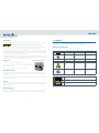
Safety Cover
A safety cover is installed on each pump head.
The safety cover protects the user from the mechanical hazard present when
the pump head is rotating.
Do not operate the pump without the safety cover installed.
Operating Conditions
Access to the rear panel is necessary because the instrument must be detached from all voltage sources before
service, repair, or exchange of parts. Allow a minimum of 2.54 cm (1 in.) space behind the instrument for proper
fan operation.
Operate the instrument using the approved power supply provided and only at the voltage specified on the
rear panel label of the instrument.
Solvents
Observe safe laboratory practices when handling solvents. If dangerous liquids are used, adequate protection
such as proper ventilation, safety glasses, etc., should be used. Refer to the Material Safety Data Sheets for the
solvents before use.
Replacement Parts
Be sure to use only replacement parts specified in this user’s guide. Do not repair or change parts which are not
listed in this user’s guide. If it is necessary to change parts not listed, please contact your local Gilson representative.
2 SÉCURITÉ
Merci de lire ces instructions avant toute installation ou utilisation de MINIPULS 3.
Symboles et avertissements
Les symboles suivants sont susceptibles d’apparaître sur l’instrument:
Symbole Signification
Direct current Courant continu Gleichstrom
Protective conductor terminal Borne de terre de protection Schutzleiteranschluss
| Electrical power ON Sous tension Netzschalter ein
O Electrical power OFF Hors tension Netzschalter aus
Caution Attention Vorsicht
Mechanical hazard Danger mécanique Mechanische Gefährdung
Les consignes de sécurité suivantes peuvent apparaître dans ce document:
AVERTISSEMENT signale une situation potentiellement dangereuse qui, si elle n’est pas évitée, peut entraîner
des blessures graves
ATTENTION signale une situation potentiellement dangereuse qui, si elle n’est pas évitée, peut entraîner
des blessures mineures ou légères
AVIS signale une situation potentiellement dangereuse qui, si elle n’est pas évitée, peut entraîner
des dommagesmatériels
R2 Pump Head with Installed Safety Cover

ENGLISH
- 7 -- 6 -
3 INTRODUCTION
Gilson’s MINIPULS 3 Peristaltic Pump was specifically designed to meet process laboratory liquid handling needs.
The MINIPULS 3 combines microprocessor speed control with a high-torque stepper motor. Chemical-resistant
pump heads, equipped with 5 or 10 stainless steel rollers, set the performance standard in producing smooth,
low-pulse flow and reproducible flow rates at higher pressures.
This user’s guide describes how to set up and operate a Gilson MINIPULS 3 Peristaltic Pump. It also describes
some of the methodology required to obtain accurate reproducible results.
Unpacking
Upon receipt of your MINIPULS 3, unpack it and check that all of the parts are included even if it is not for
immediate use. Report any loss or damage immediately. Keep the original packaging in case the MINIPULS 3
must be returned to the factory.
After unpacking the box, you should have the following:
speed control module
standard accessory package
external power supply
documentation
A pump head is required, but ordered separately.
Customer Service
Gilson, Inc. and its worldwide network of authorized representatives provide customers with the following types
of assistance: sales, technical support, applications, and instrument repair.
If you need assistance, please contact your local Gilson representative. Specific contact information can be found
at www.gilson.com. To help us serve you quickly and efficiently, please refer to Before Calling Us on page 25.
Utilisation prévue
Cet instrument est destiné à être utilisé dans un environnement de laboratoire, par un personnel technique
qualifié.
L’instrument ne doit en aucun cas être relié directement au corps humain.
Pour une utilisation correcte et en toute sécurité, il est nécessaire que le personnel qui utilise et réalise la
maintenance de l’instrument, suive les instructions contenues dans ce guide lors de l’installation, le nettoyage
et la maintenance de l’instrument.
Les consignes de sécurité suivantes doivent être respectées durant toutes les phases de fonctionnement,
d’entretien ou de réparation de l’instrument. Le non-respect de ces précautions ou des avertissements spécifiques
mentionnés dans ce guide compromet les normes de sécurité de conception, de fabrication et d’utilisation prévue
de l’instrument. Gilson décline toute responsabilité en cas d’’incapacité du client à se conformer à ces exigences.
MINIPULS 3 a été certifiée conformément aux normes de sécurité en vigueur au Canada, en Europe et aux
Etats-Unis. Merci de vous reporter aux indications mentionnées sur le panneau arrière de l’instrument ainsi
qu’au document de Déclaration de Conformité aux normes pour lesquelles l’instrument a été déclaré conforme.
Capot de protection
Un capot de protection est installé sur chaque tête de pompe.
Il protège l’utilisateur des risques mécaniques présents dès lors que
la tête de pompe tourne.
Ne pas faire fonctionner la pompe sans son capot de protection.
Conditions de fonctionnement
L’accès au panneau arrière doit être libre car l’instrument doit pouvoir
être déconnecté de sa source d’alimentation avant toute opération d’entretien, de réparation ou de remplacement
de pièces.
Ne faîtes fonctionner l’appareil qu’en utilisant le bloc d’alimentation fourni et uniquement à la tension indiquée
sur l’étiquette située à l’arrière de l’instrument.
Solvants
Respectez les Bonnes Pratiques de Laboratoire lors de la manipulation de solvants. Si des liquides dangereux sont
utilisés, assurez-vous que la ventilation est adéquate et portez en permanence un équipement de protection
individuelle (EPI), tel que : lunettes, gants et vêtements de protection.
Reportez-vous aux Fiches de Données de Sécurité pour les solvants avant toute utilisation.
Pièces détachées
Assurez-vous de n’utiliser exclusivement que les pièces détachées préconisées dans ce guide. Ne tentez pas de
réparer ou remplacer des pièces ne figurant pas dans ce guide.
Si le remplacement de pièces ne figurant pas dans ce guide s’avérait nécessaire, merci de contacter votre
représentant Gilson local.
Tête de pompe R2 équipée de son capot de protection

ENGLISH
- 9 -- 8 -
Description
Gilson’s MINIPULS 3 is a peristaltic pump, designed for transferring fluids with a high level of speed stability and
a low pulsation level. It has many applications, including the following:
transferring solutions, emulsions, suspensions, and gases at up to 200°C.
pumping liquids through chromatographic systems against a back pressure of up to 0.5 MPa (72.5 psi)
when controlled by a Gilson fraction collector, for example.
automation of biological analyses by proportionally mixing a sample with several reagents
(flow injection analysis).
continuously sampling the components of a production process (reactors, fermenters, etc.).
formation of gradients (concentration, pH, etc.).
Control of the MINIPULS 3 is from a computer via GSIOC and Gilson TRILUTION LH software, remote control by
contact closure, or manual control by front panel operation.
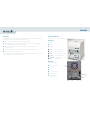
Speed Control Module
The figure shows a general view of a MINIPULS 3, before the head is installed.
Front Panel
The front panel consists of:
a keypad
a display
Slower Decrease the pump speed
Faster Increase the pump speed
Rabbit Set speed to 48 rpm for priming
Forwards Start the pump clockwise
Backwards Start the pump counter-clockwise
Stop Stop the pump
Rear Panel
The rear panel consists of:
a power on/off switch
a DC input
a fan
a contact input port
a 9-pin GSIOC port
a USB device port
(for service use only)
GSIOC
Fan
Power
on/off
switch
Contact input port
DC
input
USB device
Display
Keypad

ENGLISH
- 11 -- 10 -
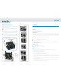
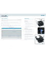
Pump Head with Safety Cover
Pump heads are composed of a rotor with idle stainless steel rollers
that press a flexible piece of tubing against a cam. In this way liquids
are pumped by a peristaltic effect.
There are two types of pump heads: the MP (standard) and the
HF (High Flow) series.
MP models have one, two, four, or eight channels (R1, R2,
R4, and R8), ten rollers, and accept tubing size from 0.2 mm
to 4 mm (internal diameter). The maximum back pressure is
0.5 MPa (72.5 psi).
HF models have two or four channels (R2/HF and R4/HF),
five rollers, and accept peristaltic tubing from 2 mm to 8 mm
(because of the V-clamp locking system). The maximum back
pressure is 0.3 MPa (43.5 psi).
R1 Pump Head
R2 Pump Head
R4 Pump Head
R8 Pump Head
R2/HF Pump Head
R4/HF Pump Head
Adjustment screwLocking key
Compression cam
Mobile retaining bar
Fixed bar
Trigger key
Fixed bar
Note: The
images above
and at left are
shown without
safety covers
for clarity.
4 SETUP
This chapter contains detailed information relating to fitting the tubing, flow rate selection, and which connectors
or couplings should be used.
Electrical
Remote Control Connections
Electrical Contacts
The MINIPULS 3 can be started and stopped remotely using electrical inputs. The direction of rotation and pump
speed may also be changed. The electrical contacts are made using the terminal block on the rear panel. The
contacts, which are numbered 1 through 8, have the functions listed below. Contacts 2, 4, and 8 are ground
connections.
Pair 1-2 is a contact input that changes the pumping direction.
Pair 3-4 is a contact input that starts/stops the pump.
Pair 5-6 is not used.
Pair 7-8 controls the speed of the pump using an analog voltage signal. For more information, refer to
Pump Speed (Analog Input) on page 26.
Making Connections
The following are needed to make connections:
2-conductor cable (20–26 gauge for each wire)
wire insulation stripper
A 6-foot piece of suitable cable (part number 709910206) is available for purchase from Gilson.
To make connections with the 2-conductor cable:
1 Cut the cable into pieces of appropriate length.
2 Strip about 8 mm of insulation from each end of the cable.
3 Remove the terminal block connector from the pump.
4 Press in the spring-loaded retainer for the appropriate terminal on the terminal block connector. Insert each
wire into the appropriate terminal on the terminal block connector and then release the spring-loaded
retainer.
5 Reconnect the terminal block connector to the liquid handler. Push the connector in as far as it will go. It
is designed to fit snugly into its receptacle.
6 Connect the opposite ends of the wires to the other device(s). Be sure to match ground connections.
7 Label each cable to identify the purpose of the connection.

ENGLISH
- 13 -- 12 -
Computer Control
To control the MINIPULS 3 from a computer, connect an appropriate Gilson interface module, or a Gilson RS-232
adapter to the computer.
Next, connect a Gilson Serial Input/Output Channel (GSIOC) cable between the interface module (or adapter)
and the MINIPULS 3, and any other Gilson devices that are controlled from the same computer.
The 9-position female plug on the GSIOC cable connects directly into the male socket on the MINIPULS 3 rear panel.
The type of interface module used, and details of how the various units in the system are interconnected,
depend on the complexity of the system.
Refer to the appropriate user’s guide, and to 6 - REMOTE CONTROL beginning on page 26, for more details relating
to GSIOC connections and commands.
Install or Change the Pump Head
Follow these procedures to install or replace a pump head.
The safety cover must be installed on the pump head before operating
the pump. Failure to do so presents a mechanical hazard to the user.
Safety cover installation instructions are provided on page16.
Remove Cover
1 Unscrew the two screws securing the cover to the pump head
until the cover can be lifted off the pump head.
2 Lift the cover off the pump head.
Open Pump Head
1 Unlock each channel of the head by pressing the trigger key
towards the roller barrel.
2 Swing the compression cam out.
Install Pump Head
1 Place the two mounting screws (part number 4011564204,
supplied in the accessory kit) through the pump head.
2 Install the pump head on top of the speed control module in
the desired position; four are possible. Do not position it with
the drain tube to the front.
3 Turn the roller shaft so that the slot at the bottom of the shaft
aligns with the tab of the rubber coupler in the speed control
module. Turning the shaft gently back and forth can help the user to engage it with the tab. When these
two parts are properly engaged, the base of the pump head rests on top of the speed control module.
4 Slide the pump head so that the two screws fall into their inserts and then tighten the screws, but do not
over-tighten.
Tubing - Selection and Fitting
Introduction
There is a small Iso-Versinic® drain tube inside the MINIPULS 3, with
an outlet at the base of the pump. The tube, which limits the risks
resulting from a rupture of the peristaltic tubing, is connected to the
motor assembly to prevent liquid from seeping inside the instrument.
All other tubing is fitted to the pump head. Gilson supplies two types
of tubing:
peristaltic tubing with two retaining stops,
connection tubing without retaining stops.
In normal operations, short lengths of peristaltic tubing are placed in the pump head. With MP pump heads, it
is essential that peristaltic tubing with two retaining stops is used. The calibrated stops ensure that the tubing
is correctly tensioned when fitted to the head.
HF models can use either type of tubing. The user then links the MINIPULS 3 with other hydraulic components
of the system (for example chromatographic columns) using connection tubing, connectors, and couplers of
appropriate diameter and material.
Type of Material
Tubing made of various materials and
with different internal diameters is
available from Gilson. The tubing sizes
and materials, recommended for MP
and HF pump heads are shown in the
table. Tubing sizes are specified as
internal diameter (ID) in millimeters (mm).
Maximum flow rates are specified in
milliliters/minute.
For any given type of pump head, the type of solution pumped determines the type of peristaltic tubing to be
used. For more information, refer to Recommended Tubing (by Application) on page 14.
More rigid materials, such as PVC, produce smaller pulsations. For example, when pumping water at 45 rpm
(pressure = 0.1 MPa or 14.5 psi) typical values for pressure pulsations are 5% with 6 mm (ID) PVC tubing and
20% with 6 mm (ID) silicone tubing.
MP Models HF Models
Flow Connecting Flow Connecting
Type mL/min mm (ID) mL/min mm (ID)
PVC up to 26 0.25 to 3.2 up to 236 2 to 8
Fluoroelastomer up to 38 0.5 to 4 - 2 to 6
Silicone up to 45 0.6 to 2.8 up to 200 2 to 7
Polypropylene up to 14 0.5 to 2 up to 171 2 to 6.4
Recommended Tubing (by Flow Rate)
Trigger key
Compression cam
Safety cover

ENGLISH
- 15 -- 14 -
Diameter and Flow Rate
Select the peristaltic tubing diameter that gives the desired flow rate after referring to Flow Rate Selection and
Adjustment on page 16. These graphs represent the values obtained in laboratory tests, where the liquid was
allowed to flow freely from the tubing against atmospheric pressure only. There was no additional back pressure
(e.g., a chromatographic column).
The selection of peristaltic tubing is a compromise between minimizing the pulsations and maximizing the
lifetime of the tubing. When making this choice, the following points should be considered:
the smaller the diameter, the smaller the pulsations and the faster the head has to rotate, leading to a
reduction of peristaltic tubing lifetime
the bigger the diameter, the bigger the pulsations, and the slower the head has to rotate, leading to
increased peristaltic tubing lifetime. That is, the pulsations increase when the flow rate decreases, and
when the internal diameter of the tubing increases.
Material PVC Silicone Polypropylene Iso-Versinic® (Viton®)
Composition Polyvinyl chloride Silicone elastomer Polypropylene-based Fluorinated elastomer
material with plasticizer
Physical characteristics Transparent, clear, rigid Translucent, beige Opaque, beige Opaque, black
Temperature range Up to 94°C Up to 230°C -60 to 135°C -20 to 200°C
Standard FDA food quality (FDA 21 CFR
177.26000 USP class VI)
Gas permeability Low High Low Impermeable to most gases
Sterilization Autoclaving Autoclaving or irridiation Autoclaving Autoclaving
Range of internal diameter 0.25 to 8 mm 0.64 to 7 mm 0.5 to 6.4 mm 0.5 to 6.0 mm
Other features Low cost Excellent biocompatibility Long service life Excellent resistance to strong acids,
Not recommended with strong oxidizing agents, aromatic and
acids, bases or solvents chlorinated solvents
Applications General use Biological Pharmaceutical and food Where high chemical resistance
is required (e.g., ICP)
Recommended Tubing (by Application)
Fitting the Tubing
Before fitting the tubing, remove the safety cover.
Install the safety cover before operating the pump.
MP Pump Heads
Only peristaltic tubing with retaining stops can be
fitted to MP pump heads.
1 Unlock each channel of the head by pressing the
trigger key (A) towards the roller barrel.
2 Position the tubing around the rollers; it is kept in
place by the plastic stops (B).
3 Swing the compression cam back and snap the
locking key. Do this one-by-one for pump heads
with more than one channel.
HF Pump Heads
Peristaltic Tubing with Retaining Stops:
1 Unlock each channel of the head by pressing the
trigger key (A) towards the roller barrel.
2 Position the tubing around the rollers; they are
kept in place by the plastic stops (B).
3 One by one, swing the compression cams back
and close the locking keys.
Peristaltic Tubing without Retaining Stops:
The peristaltic tubing is kept in place by clamps. The
movable retaining bar (C) must be fitted in such a
way that the large triangular pathways are on the
side of the fixed bar. To fit the tubing, use the same
procedure as above.
Because the R2/HF and R4/HF pumps are equipped
with 5 rollers rather than the 10 rollers as on the
other heads, pulsations may be observed at the end
of the tubing.
Adjustment screw
Locking key
Compression cam
Trigger key
Adjustment screwLocking key
Movable retaining bar
Fixed bar
Trigger key

ENGLISH
- 17 -- 16 -
Safety Cover Installation
1 Place the cover.
2 Align the screws with their inserts as shown in the image at right.
3 Tighten the screws.
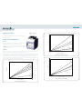
Flow Rate Selection and Adjustment
Selection
The following charts may be used to
select the approximate pump head
speed
(rpm) that is required to achieve the desired flow rate.
If it is possible to choose between tubings of different sizes (refer to the
7 - APPENDIX beginning on page 33), select a middle range tubing that
gives a middle range speed.
Adjustment
Adjust the cam pressure on the tubing to the minimum necessary to ensure pumping of the liquid. The
compression cam pressure can be adjusted using the adjustment screw.
Slowly tighten the screw until the pump starts pumping liquid inside the peristaltic tubing, and then tighten
again approximately 1/8 turn. Take care not to over-tighten the screws; it is advisable to limit pressure on tubing
to the minimum necessary for pumping liquid. Carry out final adjustment after 15 minutes of operation.
If the pump is used with a system that provides a back pressure (e.g., a chromatographic column), tighten the
screw by one or two extra turns to obtain the required flow rate.
Speed/Flow Rate Chart (Small Sized Tubing)
50
40
30
2010
0
0
1
2
P
V
C
0
.
2
m
m
P
V
C
0
.
5
m
m
F
l
u
o
r
o
e
l
a
s
t
o
m
e
r
0
.
5
m
m
Pump Head Speed (RPM)
Flow (mL/min)
0
1
2
MP Model - Small Sized Tubing
0.5
0.5
1.5 1.5
S
i
l
i
c
o
n
e
0
.
6
m
m
P
o
l
y
p
r
o
p
y
l
e
n
e
0
.
5
m
m
Speed/Flow Rate Chart (Medium Sized Tubing)
50
40
30
20
10
0
0
5
10
15
20
25
30
PVC 1 mm
PVC
2 mm
PVC
3
mm
Pump Head Speed (RPM)
Flow (mL/min)
0
10
20
30
MP Model - Medium Sized Tubing
5
15
25
Polypropylene 1 mm
Polypropylene 2 mm
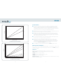
Speed/Flow Rate Chart (Large Sized Tubing)
50
40
30
20
10
0
Pump Head Speed (RPM)
Flow (mL/min)
PVC 5
mm
PVC 6 m
m
PVC
8
m
m
HF Model - Large Sized Tubing
300
200
100
0
50
150
250
Polypropylene 6.4 mm
300
200
100
0
50
150
250

ENGLISH
- 19 -- 18 -
Speed/Flow Rate Chart (Fluoroelastomer Sized Tubing)
50
4030
20
10
0
3 mm
4 mm
Pump Head Speed (RPM)
Flow (mL/min)
0
10
20
30
40
HF Model - Fluoroelastomer Tubing
0
10
20
30
40
Speed/Flow Rate Chart (Silicone Sized Tubing)
5040
30
20100
3 mm
5 mm
6 mm
Pump Head Speed (RPM)
Flow/mL/min)
0
100
200
HF Model - Silicone Tubing
50
150
0
100
200
50
150
7 mm
2 m
m
Recommendations
To ensure that consistent and accurate flow rates are maintained, systematically replace peristaltic
tubing as soon as it appears to be worn. You can reduce wear on the tubing by running at slower
speeds, by using tubing of a larger diameter, or by loosening the adjustment screws. Conversely, you
should tighten the adjustment screws to reduce the level of pulsations, which may also be reduced by
applying some back pressure, or by selecting a more rigid tubing material, like PVC.
When the pump is not in use, release the compression cams by pressing on the bevelled corners of the
trigger key and slacken the tubing. This increases the life of the tubing.
A small piece of Iso-Versinic® tubing is supplied in the standard accessory package. Fit one piece to
the pump head by pushing it onto the drain. The purpose of the drain is to remove liquid from the
pump head if the flow tubing breaks; it limits the risk of liquid seeping into the speed control module,
which contains the motor and electronic circuitry.
To prevent liquid from leaking in the event of a tube breaking, install the pump at a higher level than
the tank and collector. This arrangement eliminates gravitational flow.
If the pump is used as part of a system where a back pressure is present (for example, against a
chromatographic column), the adjustment screw must be tightened by one or two extra turns to
enable the liquid to flow. Where back pressure is present, the maximum flow rates are less than the
values that can be measured from the charts, which are plots of values measured at atmospheric
pressure (refer to Flow Rate Selection and Adjustment beginning on page 16).
Use the RABBIT key to prime the tubing (fill it with liquid); see 5 - OPERATION, beginning on page 21.
Gilson Connectors and Couplers
Gilson can supply connectors for linking peristaltic tubing with connection tubing, and couplers for other
equipment, such as low-pressure liquid chromatography columns. Refer to the 7 - APPENDIX, beginning on
page 33, for part numbers.
Connectors
Tubings are connected by simply pushing the tubings onto either end of a connector.
Plastic connectors are used for the larger diameter tubings. Three types are available:
F1179941, small bore (1 to 2 mm) to small bore,
F1179931, small bore (1 to 2 mm) to large bore (2 to 3 mm),
F1179951, large bore (2 to 3 mm) to large bore.
Metal sleeve connectors are used for very small bore tubing. Three sizes are available from Gilson for connecting
tubing from 0.25 mm ID to 0.8 mm ID.

ENGLISH
- 21 -- 20 -
Tubing ID 0.25 0.3–0.5 0.6–0.8 1–2 2–3
0.25 Sleeve
(0.6 OD)
0.3–0.5 Sleeve
(0.8 OD)
0.6–0.8 Sleeve
(1.1 OD)
1–2 Plastic Plastic
2–3 Plastic
Coupling Kits
These are used to connect the
peristaltic tubing to PTFE tubing
having flanged ends, or to connect the
peristaltic tubing to Low Pressure Liquid
Chromatography (LPLC) systems. The
coupling kit consists of a connection
screw and a cone. The figure shows a
typical connection to an LPLC system.
A Tefzel® connector
(part number 495051) is available for
connecting flexible tubing (ID 1 to 3 mm)
to tubing connection screws at Gilson
chromatography column outlets.
Couplers
Two types of couplers are available.
F1410050 consists of a set of five PVDF couplers for linking two
standard Gilson connection screws (1/4"-28 TPI).
495036 consists of one Teflon® coupler for linking connection
screws of different sizes (1/4"-28 TPI to 10 mm standard thread).
5 OPERATION
Install the pump and make the required hydraulic and electrical connections. Refer to 4 - SETUP beginning on
page 11.
Switch the pump on using the rear-panel switch.
Then refer to the following sections, which describe how to use the keypad to control the pump, or to
6 - REMOTE CONTROL beginning on page 26, if the pump is to be controlled remotely.
Keypad Functions
The keypad has six keys plus a 3-digit and 2-symbol
Liquid Crystal Display unit. The keypad functions are
summarized below.
Slower Decrease the pump speed
Faster Increase the pump speed
Rabbit Set speed to 48 rpm for
priming
Forwards Start the pump clockwise
Backwards Start the pump
counter-clockwise
Stop Stop the pump
Initialization
The safety cover must be installed on the pump head before operating
the pump. Failure to do so presents a mechanical hazard to the user.
1 Install tubing as described in 4 - SETUP beginning on page 11.
2 Make sure that the MINIPULS 3 is connected to the external power supply and that the external power
supply is connected to a power source, using the appropriate power cord for your line voltage.
3 Switch the pump ON using the rear panel switch. The speed is set at 12.5 rpm at delivery. The last speed
set before switching off is shown in rpm on the keypad display.
4 Select the desired speed by pressing:
the (-) key to decrease the displayed value,
the (+) key to increase the displayed value.
Pressing either key once changes the right-hand digit by one; pressing the key continuously makes the
speed vary at an increasing rate.
Display
Keypad

ENGLISH
- 23 -- 22 -
5 To start the pump, press the or the key, depending on the desired direction of rotation. A (+) sign or
a (-) sign is then displayed to the left of the speed value.
Press the RABBIT key to purge or to prime the tubing. The RABBIT key cannot be used until either the
or the key has been pressed. The direction of pumping can be changed without stopping the pump.
Pressing the RABBIT key gives the maximum speed of 48 rpm in the previously selected direction.
When pressed, the display shows (+ - - -) or (- - - -), but the previous speed is stored in memory.
If pressed a second time, the pump rotates at the preset speed; the same is applicable if either
the or the key is pressed.
The STOP key stops the pump and stores the displayed speed for the next start up command. If the key is
pressed when the pump is revolving at the RABBIT speed, the last speed selected before RABBIT selection
is
stored for the next start up command.
When the pump is remote-controlled,
a symbol is displayed above the (+) or (-) sign.
Autostart Function
The Autostart Function enables the pump to restart pumping at power on, in a predetermined way. When the
power is restored, the pump idles regardless of its status when the power was cut. The display flashes until any
key is pressed.
The Autostart Function has three modes, as described in the next three paragraphs; mode selection is described
in the following paragraph.
Non-autostart Mode
During mode selection, this mode is indicated by a dash “-” to the left of the identification number. In this mode,
each time the speed is changed, the current speed is stored in non-volatile memory (provided no other key
is pressed within three seconds of selecting the speed). Subsequently, when the pump is switched on, the
previously selected speed is shown on the display. The pump operates at this speed when either the or the
key is pressed.
Autostart Mode
During mode selection, this mode is indicated by a letter “A” to the left of the identification number. In this mode,
the last speed and direction are stored in non-volatile memory (provided no other key is pressed within three
seconds of selecting the speed or direction).Subsequently, when the pump is switched on, the pump operates
in the way that it did before it was switched off.
Hold Mode
During mode selection, this mode is indicated by a letter “H” to the left of the identification number. In this mode,
although speed and direction changes are effective at the time that they are made, the non-volatile memory
is not updated. When the pump is switched on again, the pump operates in a way that is pre-determined by
the user, regardless of any changes that were made before it was switched off.
To set the pre-determined values that are effective when the pump is switched on, proceed as follows.
1 Put the pump in the “Autostart” mode (see Mode Selection).
2 Set the speed and direction, wait for five seconds, and then switch off.
3 Switch on while pressing the STOP key, then select the “Hold” mode using the RABBIT key.
4 Press the STOP key to exit the configuration program.
The values set in this mode are preserved until the mode is changed to either Autostart or Non-autostart.
Mode Selection
To select the mode:
1 Turn the power off.
2 Press the STOP key, and while holding it, turn the power on again.
3 The display then shows one of three symbols to indicate the current mode (“A”, “H”, or “-”) followed by a
2-digit identification number (see Changing the Unit ID).
4 Press the RABBIT key until the symbol indicating the required mode appears.
5 Press the STOP key to validate the selection.
Changing the Unit ID
The unit ID identifies each instrument to Gilson software packages that can issue GSIOC commands to the
instrument. There is no need to change this number unless it is the same as that assigned to another Gilson
instrument that’s also connected along the GSIOC.
At the factory, Gilson set the unit ID for the MINIPULS 3 to 30.
To change the unit ID, turn the power OFF. Turn the power ON again while pressing the STOP key. The display
shows “A30”. Using the “+” and “-” keys, select the desired ID number. Then, press the STOP key to quit.

ENGLISH
- 25 -- 24 -
Maintenance and Troubleshooting
Routine maintenance
The only routine maintenance required is to clean up any spilled liquids and periodically to clean the outside
of the MINIPULS 3 with a damp cloth.
Replace tubing when it shows signs of wear, such as flatness or cracking. Damaged tubing can cause excessive
pulsations and erratic flow.
Troubleshooting
Problem Solution
Blank Display If the display is blank when the pump is turned ON, proceed as follows:
If the fan does not run.
Check the power connection and (if necessary) replace the power supply. If the display remains blank, contact your
local Gilson representative.
If the fan runs.
Check the electronics by pressing the or key. If the pump head does not rotate, there could be a problem
with the electronics (faulty board). Contact the service agency.
Dead Keypad If the “+” and the “-” keys have some effect, the pump is probably under remote control. If not, the keypad could
need replacing. Contact the service agency.
No GSIOC Response Check the GSIOC ID number, GSIOC cables, connectors, and GSIOC interface module. If these actions fail to correct
the problem, there could be a problem with the electronics (faulty board). Contact your local Gilson representative.
Worn or Faulty Pump Head
Replace the pump head.
Repair and Return Policies
Before Calling Us
Your local Gilson representative will be able to serve you more efficiently if you have the following information:
• serial number and model number of the instruments involved.
The serial number for the MINIPULS 3 is located on the rear panel near the fan.
• installation procedure you used
• list of concise symptoms
• list of operating procedures and conditions you were using when the problem arose
• list of all instruments in the configuration and the connections to those instruments
• list of other electrical connections in the room
Warranty Repair
Units covered under warranty will be repaired and returned to you at no charge. If you have any questions about
applicability, contact your local Gilson representative.
Non-Warranty Repair
For out-of-warranty repairs, contact your local Gilson representative who will discuss service options with you
and can assist in making arrangements to return the equipment, if necessary.
Return Procedure
Contact your local Gilson representative to obtain authorization before returning any Gilson equipment. To
return a piece of equipment:
Carefully pack the unit to prevent damage in transit. Check with your local Gilson representative regarding proper
method of shipment. No responsibility is assumed by Gilson or your local Gilson representative for damage
caused by improperly packaged instruments. Indicate the authorization on the carton and on the packing slip.
Always insure for the replacement value of the unit.
Include a description of symptoms, your name, address, phone number, and purchase order to cover repair
costs, return and shipping charges, if your institution requires it.
Unit End-of-Life
When a unit reaches the end of its useful life, refer to www.gilson.com for directions and information
on the end-of-life policy. This is in accordance with the European Union Directive 2002/96/EC on
Waste Electrical and Electronic Equipment (WEEE).

ENGLISH
- 27 -- 26 -
START
STOP
ANALOG
INPUT (0-5 V)
0-5 V, giving 0 - 100%
of the selected speed
0 V Active (Start)
0 V Active (CCW)
5 V Inactive (CW)
5 V Inactive (Stop)
Pump Speed
Start/Stop
Direction
Control
0
9
6 REMOTECONTROL
Remote contact control is not available if the MINIPULS 3 is already under GSIOC or keypad control. To transition
from keypad control to remote control, the pump must be in an idle state.
Electrical Contact Control
There are two contact inputs and one
analog input available on the 8-pin
terminal block connector. These TTL
low-level active inputs (0–5V) have a
threshold of 2 Volts and are pulled up
to 5 Volts with a high impedance. The
connection diagram is shown at right.
Start/Stop Input
(ContactInput)
The pump can be started by closing the
start/stop input, and stopped by opening it. The input is closed by shorting pin 3 to ground (pin 2, 4, or 8).
Closing this input starts the pump in the direction selected by the Direction Control input at the speed defined
by the Analog Input. When the pump is started using this input, the keypad has no effect until the Start/Stop
contact is opened again.
Direction Control (Contact Input)
When the Direction Control contact is opened, the pump rotates in the forward direction (clockwise). When
this contact is closed, the pump rotates in the reverse direction (counter-clockwise). The direction of rotation
may be changed while the pump is running, in which case the transition is immediate.
Pump Speed (Analog Input)
A DC voltage (0–5V) or a resistance (resistor or potentiometer) between pin 7 and ground can be used to change
the rotation speed as described below.
Voltage control: Effective Speed = (Selected Speed x Applied Voltage)/5 Volts
The Applied Voltage is expressed in Volts.
The Selected Speed is displayed before the Start/Stop input is activated.
The Effective Speed is displayed after the Start/Stop input is activated.
Resistance control: Effective Speed = (Reference Speed x Resistance)/(Resistance + 68)
The resistance is expressed in kOhms.
The Reference Speed is obtained with an infinite resistance (open circuit).
Control by Gilson Devices
Please refer to the respective technical manuals. For more details, please contact your local Gilson representative.
GSIOC Control
Gilson systems feature a two-way communication interface between the computer and most Gilson instruments.
Communication occurs along the Gilson Serial Input Output Channel (GSIOC).
Each instrument is identified by a unique unit ID, designated by a number between 0 and 63.
The default unit ID of the MINIPULS 3 is 30.
Using the computer and software, you:
• specify the instrument you want to control
• issue commands that set operating parameters, control operation, or request information from that instrument
GSIOC Commands
There are two kinds of commands that you can send over the GSIOC:
• Buered commands send instructions to the instrument. These commands are executed one at a time.
• Immediate commands request status information from the instrument. These commands are executed
immediately, temporarily interrupting other commands in progress.
For more information on GSIOC, refer to the GSIOC Technical Manual (part number LT2181).
Control Modes
The MINIPULS 3 offers two levels of digital control mode: Keypad and Remote.
The Keypad mode is the default. The MINIPULS 3 normally works through the keypad and responds
to immediate commands through GSIOC. It is similar to the local mode of some computer-controlled
devices.
In the Remote mode, the keypad is locked and the unit receives commands and key-codes from the
GSIOC. Contact inputs are disabled.

ENGLISH
- 29 -- 28 -
Command Type Mode Function
% I Keypad and Remote Request Module Identification
? I Keypad and remote Request Mode Status
$ I Keypad and remote Master Reset
I I Keypad and remote Request Contact Input Status
K B Remote Input Remote Keystroke
K I Keypad and remote Request Keypad Status
R B Remote Set Speed
R I Keypad and remote Read Display
S B Keypad and remote Set External Mode
V I Keypad and remote Request Analog Input Status
Command Descriptions
Below is the list of available commands in
alphabetical order. This list may be used as a quick
reference guide.
A detailed description of each command is provided.
The default response given in some of the following
descriptions is the response returned by the
MINIPULS 3 when an immediate command is sent
at power on, or after a master reset. The response
to a buffered command is a period (.).
Because the controller command buffer is 40
characters long, buffered command strings can be
as long as 39 characters, the last character being the
CR (Carriage Return) ASCII code.
Command %
Type Immediate
Mode Keypad and Remote
Function Module identification
Response format “312Va.b.c.d” where
a.b.c.d identifies the software version
Command ?
Type Immediate
Mode Keypad and Remote
Function Request Mode Status
Response format “K” for keypad, “R” for remote
Default response “K”
Command $
Type Immediate
Mode Keypad and Remote
Function Master reset
Response format $ is echoed
Command I
Type Immediate
Mode Keypad and Remote
Function Request Contact Input Status
Response format “ab” where
“a” reflects pin 3 (START/STOP input)
“b” reflects pin 1 (CW/CCW input)
“a” and “b” take values of either 0 or 1
“1” is an inactive or high input (open)
“0” is an active or low input (closed)
Default response “11”
Command K
Type Buffered
Mode Remote
Function Input remote keystrokes. Mimic key actions.
Syntax K codes
Parameters String of characters as follows:
“<” = backwards (CCW)
“>” = forwards (CW)
“+” = faster
“-” = slower
“H” = stop
“&” = rabbit
Comments All other characters are ignored. A buffered “K” command must be the last in a command string.
Note: To make this command work properly, the MINIPULS 3 should not be disconnected from the system master until the buffer is empty. To ensure that
this is true the master should send another command (such as an empty string) immediately after any string containing a “K” command. Completion of the
first string is implied as soon as the second is accepted

ENGLISH
- 31 -- 30 -
Command K
Type Immediate
Mode Keypad and Remote
Function Request keypad status
Response format “cs” where
“c” is the code of the last key pressed.
“<” = backwards (CCW)
“>” = forwards (CW)
“+” = faster
“-” = slower
“H” = stop
“&” = rabbit
“s” is the key’s status
“!” if the key was pressed after the last request
“-” if the key remains pressed after the last request
“ ” a space means that no key was pressed
Default response “$”
Command R
Type Buffered
Mode Remote
Function Set speed
Syntax Rrrrr
Parameter rrrr is the new speed in hundredths of a revolution per minute (ranging between 0 and 4800)
Comment An input of “R” is interpreted as “R0”
Command R
Type Immediate
Mode Keypad and Remote
Function Read Display
Response format “dXX.XXca” where
“d” is the direction status
“ ” a space if stopped
“+” if CW “-” if CCW
“XX.XX” is the speed status in rpm
“—.—” at full speed (rabbit)
“c” is the control status
“K” if started through the keypad
“R” if started through the contacts or set to remote mode through GSIOC
“a” is the autostart condition
“*” if in autostart condition (display flashing)
“ ” a space if not in autostart
Default response “12.50K” when the pump is new
Command S
Type Buffered
Mode Keypad and Remote
Function Set External Control Mode. Switches between modes.
Syntax Sm
Parameter “m” = “K” for keypad or “R” for remote mode
Command V
Type Immediate
Mode Keypad and Remote
Function Request Analog Input Status
Response format “vvv” where “vvv” is a three-character code (range 000 - 255)
Default response “255” (255 corresponds to 5 V, or open circuit)

ENGLISH
- 33 -- 32 -
Examples
Example 1:
To set the speed at 25 rpm.
Command Comment
(I) $ ; Master Reset
(B) SR ; Set remote mode
(B) R2500 ; Set speed to 25.00 rpm
This sets the speed without starting the pump; it does not rotate.
Example 2:
To mimic the key entry sequence CCW+FULL SPEED.
Command Comment
(I) $ ; Master Reset
(B) SR ; Set remote mode
(B) K< ; Select CCW direction
(B) K& ; Full speed (rabbit)
Pump Head
Model R1 R2 R4 R8 R2/HF R4/HF
F117604 F117800 F117606 F117608 F117830 F117831
Speed Control Module
Model MP1 MP2 MP4 MP8 MP2/HF MP4/HF
Channels 1 2 4 8 2 4
F155001
Item Qty Part Number
Peristaltic tubing pack 1 F117930
- 1 x PVC tubing (i.d. 0.4 mm) for MP models
- 1 x PVC tubing (i.d. 3.2 mm) for MP and HF models
- 1 x silicone tubing (i.d. 7 mm) for HF models
(Each tubing is just over 0.4 m long and is tted with retaining stops)
Drain tubing (Isoversinic, 200 mm x 10 mm x 7 mm) 1 F155081
Pump head screw 2 4011564204
Power cord for 220-240 V for external power supply 1 7080316106
Power cord for 100-120 V for external power supply 1 7080318107
24V external power supply 1 549512025
Terminal block connector (8-pin) 1 6383087203
User’s Guide 1 LT801121
7 APPENDIX
This chapter contains part numbers and technical data (specifications).
Part Numbers
Six pump heads are available: four
standard models (1, 2, 4, or 8 channels)
and two HF models (2 or 4 channels).
Pump heads are ordered separately. A
speed control module is also required
and is supplied with an accessory
package. Refer to the tables for part
numbers.
Standard Accessory Package
Refer to the table for a listing of the items
included in the standard accessory package.

ENGLISH
- 35 -- 34 -
Part No. Description
F117985 Set of 5 Stainless steel connectors 0.6 mm OD
F117986 Set of 5 Stainless steel connectors 0.8 mm OD
F117987 Set of 5 Stainless steel connectors 1.1 mm OD
Part No. Description
F1179931 Set of 10, PVDF connectors for 1-2 mm id tubing to 2-3 mm
F1179941 Set of 10, PVDF connectors for 1-2 mm id tubing to 1-2 mm
F1179951 Set of 10, PVDF connectors for 2-3 mm id tubing to 2-3 mm
Part No. Description
F117932 Set of 12 PVC Flow tubes of 0.25 mm id
F117933 Set of 12 PVC Flow tubes of 0.38 mm id
F117934 Set of 12 PVC Flow tubes of 0.51 mm id
F117936 Set of 12 PVC Flow tubes of 0.76 mm id
F117938 Set of 12 PVC Flow tubes of 1.02 mm id
F117940 Set of 12 PVC Flow tubes of 1.30 mm id
F117942 Set of 12 PVC Flow tubes of 1.52 mm id
F117943 Set of 12 PVC Flow tubes of 1.65 mm id
F117945 Set of 12 PVC Flow tubes of 2.06 mm id
F117946 Set of 12 PVC Flow tubes of 2.29 mm id
F117948 Set of 12 PVC Flow tubes of 2.79 mm id
F117949 Set of 12 PVC Flow tubes of 3.16 mm id
Part No. Description
F1825054 Set of 5 (screw & cone) for 1.0-1.65 mm id tubing (3 mm max. OD)
F1825056 Set of 5 (screw & cone) for 2.0-2.3 mm id tubing (4 mm max. OD)
Part No. Description
495036 One PTFE coupler to connect high presure tube-end fittings between
1/4”-28 TPI and 10 mm standard thread.
F1410050 Set of 5 PVDF couplers for linking two standard Gilson connection
screws (1/4”-28 TPI).
Additional Accessories
Additional accessories such as tubing and connectors can be supplied by Gilson. These items are described in
4 - SETUP beginning on page 11, and are listed below.
Connectors
Metal Sleeve Connectors for Small Bore
Tubing
Polyvinylchloride (PVC) Connection
Tubing
Part No. Description
F117952 3 meters tubing 0.25 mm id
F117953 3 meters tubing 0.38 mm id
F117954 3 meters tubing 0.51 mm id
F117956 3 meters tubing 0.76 mm id
F117958 3 meters tubing 1.02 mm id
F117960 3 meters tubing 1.30 mm id
F117962 3 meters tubing 1.52 mm id
F117963 3 meters tubing 1.65 mm id
F117965 3 meters tubing 2.06 mm id
F117966 3 meters tubing 2.29 mm id
F117968 3 meters tubing 2.79 mm id
F117969 3 meters tubing 3.16 mm id
Part No. Description
F117970 3 meters PVC tubing 4 mm id
F117980 3 meters PVC tubing 5 mm id
F117981 3 meters PVC tubing 6 mm id
F117982 3 meters PVC tubing 8 mm id
Part No. Description
F1817741 Set of 4 Isoversinic flow tubes 0.5 mm id
F1817743 Set of 4 Isoversinic flow tubes 1.0 mm id
F1817745 Set of 4 Isoversinic flow tubes 2.0 mm id
F117747 Set of 4 Isoversinic flow tubes 3.0 mm id
F117749 Set of 4 Isoversinic flow tubes 4.0 mm id
Part No. Description
F117740 3 meters Isoversinic tubing 0.5 mm id
F117742 3 meters Isoversinic tubing 1.0 mm id
F117744 3 meters Isoversinic tubing 2.0 mm id
F117746 3 meters Isoversinic tubing 3.0 mm id
F117748 3 meters Isoversinic tubing 4.0 mm id
F117750 3 meters Isoversinic tubing 6.0 mm id
Polyvinylchloride (PVC) Connection
Tubing (HF)
For use with high flow pump heads only.
Plastic Connectors for Large Bore Tubing
Connector Kits for Flanged Tubing
Couplers
Polyvinylchloride (PVC) Tubing
For use with medium concentration aqueous
solutions (acidic or basic).
Polyvinylchloride (PVC) Calibrated
Peristaltic tubing
0.4 meter lengths of PVC peristaltic tubing
(with stops)
Fluoroelastomer Tubing
(Iso-Versinic®/Viton®)
For use with strong acids, oils, aromatic and
chlorinated solvents.
Iso-Versinic Calibrated Peristaltic tubing
0.40 meter lengths of Iso-Versinic peristaltic
tubing (with stops).
Iso-Versinic Connection Tubing

ENGLISH
- 37 -- 36 -
Reference Description
F1825111 Set of 4 Silicone flow tubes 0.6 mm id
F1825112 Set of 4 Silicone flow tubes 1.0 mm id
F1825113 Set of 4 Silicone flow tubes 2.0 mm id
F1825114 Set of 4 Silicone flow tubes 2.8 mm id
Part No. Description
F1825131 3 meters Silicone tubing 0.6 mm id
F1825132 3 meters Silicone tubing 1 mm id
F1825133 3 meters Silicone tubing 2 mm id
F117975 3 meters Silicone tubing 3 mm id
F117976 3 meters Silicone tubing 4 mm id
F117977 3 meters Silicone tubing 5 mm id
F117978 3 meters Silicone tubing 6 mm id
F117979 3 meters Silicone tubing 7 mm id
Part No. Description
F1825101 Set of 4 Polypropylene Flow tubes of 0.5 mm id
F1825102 Set of 4 Polypropylene Flow tubes of 1.0 mm id
F1825103 Set of 4 Polypropylene Flow tubes of 2.0 mm id
Part No. Description
F1825121 3 meters Polypropylene tubing 0.5 mm
F1825122 3 meters Polypropylene tubing 1.0 mm
F1825123 3 meters Polypropylene tubing 2.0 mm
F1825124 3 meters Polypropylene tubing 3.2 mm
F1825125 3 meters Polypropylene tubing 6.4 mm
Part No. Description
6383087203 CONN, TERM BLK 8PIN 2.5MM
Silicone Tubing
Silicone Calibrated Peristaltic tubing
0.40 meter lengths of Silicone peristaltic tubing
(with stops).
Silicone Connection Tubing
Polypropylene (PharMed®) Tubing
For use in the pharmaceutical and food
industries.
Polypropylene Calibrated Peristaltic
Tubing
0.4 meter lengths of peristaltic tubing
(with stops).
Polypropylene Connection Tubing
Electrical Connector
Technical Specications
Operating Temperature: 4–40°C
No warm-up time is required before operation
Position: Upright only (vertical ±5°).
Head Speed: 0.01 to 48 rpm
Torque: Greater than 3 Nm at any speed below 25 rpm, at or above the nominal voltage (24V DC)
Motor Speed Stability: 0.5% for any variation, torque, or temperature
Continuous Speed Adjustment: From 0 to 48 rpm by 0.01 increments up to 9.99 rpm, above 9.99 rpm by
0.1 increments
Flow Rate Range:
Maximum: MP model 40 mL/min (1.8 L/h, 4 mm tubing), HF model 250 mL/min (15 L/h, 8 mm tubing)
Minimum: 0.3 µL/min (0.25 mm tubing)
Maximum Back Pressure: 0.5 MPa (72.5 psi) for MP models, 0.3 MPa (43.5 psi) for HF models
Peristaltic Tubing Diameter: 0.25 to 4 mm (ID) for MP models, 2 to 8 mm (ID) for HF models
Power Requirements: External Power Supply
Voltage Input 100–240V AC, 50 to 60 Hz
Voltage Output 24V DC, 1.7A, 41W
Dimensions without pump heads (W x D x H): 15.0 x 17.5 x 18.5 cm (5.9 x 6.9 x 7.3 in.)
Humidity: Up to 80%
Weight: 2.5 kg (5.5 lbs.)
Altitude: Up to 2000 m

LT801121-16 ©2013 Gilson, Inc. | All rights reserved.
Gilson, Inc.
PO Box 620027 | Middleton, WI 53562-0027, USA
Tel: 800-445-7661 or 608-836-1551 | Fax: 608-831-4451
Gilson S.A.S.
19, avenue des Entrepreneurs | BP 145, F-95400 Villiers-le-Bel, France
www.gilson.com
-
 1
1
-
 2
2
-
 3
3
-
 4
4
-
 5
5
-
 6
6
-
 7
7
-
 8
8
-
 9
9
-
 10
10
-
 11
11
-
 12
12
-
 13
13
-
 14
14
-
 15
15
-
 16
16
-
 17
17
-
 18
18
-
 19
19
-
 20
20


dans d''autres langues
- English: Gilson Minipuls 3 User manual
Documents connexes
Autres documents
-
 Hach TPM870 Manuel utilisateur
-
lbx instruments LBX P10 Manuel utilisateur
-
US Water Stenner Series SVP Manuel utilisateur
-
CTX MyPOOL Series Operating
-
 Hach SIP 10 User Instructions
-
 Hach Lachat QuikChem Manuel utilisateur
-
 Hach SIP 10 kit User Instructions
-
 FibaTape FDW8645-U Guide d'installation
-
Thermo Scientific TSG Series Mode d'emploi
-
 Thermo Fisher Scientific TSG Series Manuel utilisateur


