La page est en cours de chargement...

TPM870 1
TPM870
Turbidity Pump Module
User’s Manual
Manuel d'Utilisation

TPM870 2
D21T069 . Printed by Radiometer Analytical SAS . France . 2008-11C

TPM870 3
General presentation
The TPM870 Turbidity Pump Module is used to interface a turbidimeter
fitted with an analogue measurement output (example the 2100AN IS
turbidimeter from Hach) and a Titration Workstation of the TIM8xx/
TIM9xx range or a ION450/ION570 Ion Analyser.
The TPM870 allows to automate turbidity measurements in association
with pH and conductivity measurements and a potentiometric titration
like water hardness determination for example.
With a PC connected to the Titration Workstation and the TitraMaster 85
PC software, the analysis can be fully automatised and the
measurements collected on the PC.
Présentation générale
Le Module Pompe Turbidité TPM870 est utilisé pour interfacer un
turbidimètre équipé d'une sortie de mesure analogique (exemple : le
turbidimètre 2100AN IS de chez Hach) avec une Station de Titrage de la
gamme TIM8xx/TIM9xx ou un Analyseur d'Ions ION450/ION570.
Le TPM870 permet d'automatiser la mesure de la turbidité en associa-
tion avec la mesure de pH, de conductivité et un titrage potentiométrique
comme la détermination de la dureté de l'eau par exemple.
Avec un PC connecté à la Station de Titrage et le logiciel PC
TitraMaster 85, l'analyse peut être entièrement automatisée et les
mesures récupérées dans le PC.

TPM870 4
ContentsContents
ContentsContents
Contents
1. Setting up ....................................................................... 5
1.1 Equipment used ........................................................................ 5
1.2 Hydraulics circuit ...................................................................... 6
1.3 Electrical connections ............................................................... 15
1.4 Preparing the measurement system .......................................... 17
2. Starting an application .................................................. 20
3. Running an analysis ......................................................26
4. Recommendations for use and maintenance ............. 29
Appendix A - Technical specifications ................................. 31
Appendix B - The "Selectors" switches ............................... 32
Appendix C - Packing list and accessories ......................... 35
1. Installation et montage .................................................. 37
1.1 Matériel utilisé ........................................................................... 37
1.2 Circuit hydraulique .................................................................... 38
1.3 Connexions électriques ............................................................. 47
1.4 Préparation du système de mesure ........................................... 49
2. Lancement d'une application ....................................... 52
3. Déroulement d'une analyse .......................................... 58
4. Conseils d'utilisation et d'entretien ............................. 61
Annexe A - Caractéristiques techniques ............................. 63
Annexe B - Les interrupteurs "Selectors" ........................... 64
Annexe C - Liste de colisage et accessoires ....................... 67
SommairSommair
SommairSommair
Sommair
ee
ee
e

TPM870 5
1. Setting up
The TPM870 instrument has been developed to meet the requirements of
electrochemical applications dedicated to water analysis. It is therefore
aimed at experienced users who have the knowledge required to operate
the instrument and implement the security instructions enclosed. We
accept no responsibility for using this measurement system (including
peripheral devices) under conditions that are not specified in this User's
Manual. This system must not, under any circumstances, be used to
perform tests on living beings.
1.1 Equipment used
. A TPM870 Turbidity Pump Module to add turbidity measure
automation to TitraLab or MeterLab system configurations (see table
below), R21T112 (in 230 V) or R21T113 (in 115V).
. A turbidimeter with an analogue measurement output (example:
2100AN IS turbidimeter from Hach).
. A manual Flow Cell Kit for 2100AN IS turbidimeter from Hach.
. < 0.1, 20, 200, 1000, 4000 and 7500 NTU standards.
. A Titration Workstation of the TIM8xx/TIM9xx range or an Ion
Analyser IONxxx. The TIM8xx, TIM9xx or IONxxx used depends on
the applications to be done.
English
ION450 TIM865
TIM9xx
TIM870ION570
pH measurements
Conductivity measurements -
ISE Direct measurements
Potentiometric titrations - -
-
. A SAC950 sample changer fitted with a 36-position turntable for
180 ml PP sample beakers.
. A PC fitted with TitraMaster 85 Titration Software.
TitraMaster 85, version 5.1.0 or higher.

TPM870 6
0 0 0
0 0 0 0 0
1
2
4
5
Rinsin
g
Sample
beaker
3
Waste
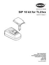
1.2 Hydraulics circuit
1.2.1 Operation principle
The sample is driven into the turbidity flow cell (3) with pump (2) after
electrovalve (1) has opened. The sample is evacuated to a waste.
Rinsing water is driven into the turbidity flow cell (3) with pump (2) after
electrovalve (4) has opened. Rinsing water is evacuated to a waste as
for the sample.
Electrovalves (1) and (6) and pump (2) are monitored via the TTL
commands of the instrument used for the electrochemical
measurements. Manual rinse can be triggered by pushing button (5).

TPM870 7
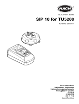
1.2.2 Setting up the hydraulics circuit
We recommend you to place the Hach 2100AN IS turbidimeter onto the
TPM870 and the Titration workstation or Ion Analyser on the left or right
side of these two instruments. The waste and rinse water containers can
be placed on the floor. Have in mind that around 150 ml of rinse water
are required per sample analysis. According to the number of samples to
analyse, it could be interesting to take the rinse water directly from an
ion exchanging column output.
Recommended position and space required
The Sample Changer can be placed on the right or on the left of the
system defined above. Place the extension burette (ABU52 or ABU62)
beside the Titration workstation or Ion Analyser.
TPM870
Turbidimeter
Titration
Workstation
or Ion
Analyser
110 cm
60 cm
English

TPM870 8
1. Setting up the pump head
Mount the peristaltic pump head (1) onto the front panel of the TPM870.
0
0 0 0
0 0 0 0 0
1
Pump
Manual Rinse
Power
Sample
Rinse
Turbidity
Meter
Power
Sample
Rinse
Turbidity
Meter
Pump
Manual Rinse
0
0 0 0
0 0 0 0 0
'Clic'
Pump
Manual Rinse
Power
Rinse Sample
Turbidity
Meter
0
0 0 0
0 0 0 0 0
Open the pump

TPM870 9
2. Setting up the pump head tubing
Softening silicone tubing (2)
Before a first time use, follow this procedure to soften the silicone
tubing (2) ∅ = 4.8/8.0 mm:
English
Pump
Pump
Manual Rinse
Power
Power
Power
Rinse Sample
Turbidity
Meter
2
Pump
Rinse
Turbidity
Meter
Perform 3 manual rinses
Manual Rinse
Sample
Rinse
Turbidity
Meter
Manual Rinse
Sample
0
0 0 0
0 0 0 0 0
0
0 0 0
0 0 0 0 0
Open the pump
Remove the tubing branch
Place this tubing branch
into the pump head and
close the pump
Adjust the tubing diameter
4.8
1.6

TPM870 10
Pump
Pump
Rinse
Turbidity
Meter
Perform 3 manual rinses
Manual Rinse
Sample
Rinse
Turbidity
Meter
Manual Rinse
Sample
0
0 0 0
0 0 0 0 0
Remove the tubing branch
Pump
Manual Rinse
Power
Power
Power
Rinse Sample
Turbidity
Meter
2
Place the other tubing branch into the pump
head then close the pump
0
0 0 0
0 0 0 0 0
Open the pump

TPM870 11
Place silicone tubing (2) ∅ = 4.8/8.0 mm into pump head (1). Note that
this Y-shaped tubing is fitted with 3 male couplers (a). Check the
presence and the correct positioning of these 3 couplers.
Pump
Manual Rinse
Power
Rinse Sample
Turbidity
Meter
2
Pump
Manual Rinse
Power
Sample
0
0 0 0
0 0 0 0 0
Rinse
Turbidity
Meter
a
a
Pump
Manual Rinse
Power
Rinse Sample
Turbidity
Meter
Adjust the tubing diameter
4.8
1.6
Note: Removing pump head
Pump
Manual Rinse
Power
Sample
Rinse
Turbidity
Meter
0
0 0 0
0 0 0 0 0
Press here
Pump
Manual Rinse
Power
Sample
Rinse
Turbidity
Meter
0
0 0 0
0 0 0 0 0
English

TPM870 12
Pump
Manual Rinse
Power
Sample
0
0 0 0
0 0 0 0 0
Rinse
Turbidity
Meter
To turbidity cell
To rinsing bottle
(demineralised water)
c
2
4
To sample beaker
b
b
b
3
d
5
3. Setting up the TPM870/turbidity cell tubing, suction tubing and
TPM870/rinse bottle tubing
Check the presence and correct positioning of the 3 female couplers (b),
strainer tip (c), and turbidimeter suction tube (d). Set up PVC tubings (3)
(L = 3.25 m, ∅ = 3/5 mm), (4) (L = 3 m, ∅ = 4/6 mm) and (5)
(L = 3 m, ∅ = 3/5 mm) by locking couplers (a) of tubing (2) into couplers
(b) of the 3 relevant tubings.

TPM870 13
English
4. Setting up the turbidity cell
Mount the end of tubing (4) (L = 3 m, ∅ = 4/6 mm) on the turbidity cell
"IN" input (6).
Set up the Y-shaped PVC tubing (7) (L = 50 cm, ∅ = 3/5 mm) between
the waste bottle and the 2 turbidity cell (6) "OUT" outputs.
Note:
Humidifying the tubing ends with water facilitates all these operations.
If required, adjust the configuration of your installation by cutting each
tubing to a suitable length.
Clean the cell following the procedures of the turbidimeter User's Manual.
6
IN
4
OUT
6
Waste bottle
or sink
7
4

TPM870 14
Remove the turbidimeter cover (9) as described in the turbidimeter
User's Manual.
Install the turbidity cell (6) in the sample compartment of the
turbidimeter. Fix the 3 cell tubings by pressing them into the slots
provided.
Cover the cell with the cell light cover (8).
8
9
6

TPM870 15
1.3 Electrical connections
English
TPM870
Mains socket
115
230
1 2 3 4
1 2 3 4
1 2 3 4
RS232C
Pump
Speed
12 4
Selectors
Analyser
Turbidimeter
Line Fuse T2A L 250V
115/230Vac 47.5-63Hz 200 VA
Power On
MADE IN FRANCE RADIOMETER ANALYTICAL SAS
I
O
SERIAL I/O
AIR PURGE
REMOTE
RECORDER
20 PSIG MAX
WARNING:
FOR CONTINUED PROTECTION
AGAINST FIRE HAZARD, REPLACE
ONLY WITH THE SAME TYPE AND RATING OF FUSE.
AVERTISSEMENT: POUR UNE PROTECTION
CONTINUE CONTRE LE FEU REMPLACER LE
FUSIBLE PAR UN DU MEME TYPE ET DE MEMES
CARACTERISTIQUES.
T, 1.6A, 250 V
Turbidimeter 2100AN IS
Titration Workstation
or Ion Analyser
12
10
11

TPM870 16
Cable Description Part no.
10 TPM870 Line cord A95S001 (230V)
A95S002 (115V)
11 Cable turbidimeter "Recorder" A95R251
analogue output socket to TPM870
"Turbidimeter" socket
Jack stereo 6.35/1.2 m/DIN-5m
12 Cable TPM870 "Analyser" output A95R252
to TIM8xx, TIM9xx or IONxxx
TTL 12V OUT / TTL 5V OUT / E1 sockets
MAB-6m/1.2 m/BNC+4 micro-banana

TPM870 17
1.4 Preparing the measurement
system
1.4.1 TPM870
Before switching on the TPM870, check on the rear panel that the
voltage selection switch setting (115 V or 230 V) corresponds to the
mains voltage.
Mains voltage = 230 V
Mains voltage = 115 V
Connect the TPM870 to the mains using the 3 lead connecting cord
supplied (see paragraph 1.3, cable 10).
Important:
The TPM870 must be connected to an earthed mains socket for
safety reasons.
The power supply connector on the rear panel must remain
accessible and close to the user (2 m maximum) so that you can
quickly disconnect the cables in case of emergency.
Switch on the TPM870 ("POWER ON" switch on the rear panel).
English
115
230
115
230

TPM870 18
1.4.2 Hydraulics circuit
On delivery, the useful volume of a 120 ml beaker is pumped in around
35 seconds. Although not recommended, the pump flow rate can be
decreased by turning the "Pump speed" screw potentiometer (see figure).
Please note that the factory tuning corresponds to the upmost position of
the screw potentiometer.
A 15 second manual rinse can be triggered by pushing a button. The
duration of a manual rinse is set on instrument delivery using set no. 1 of
switches (see figure). This duration can be changed but this operation is
not recommended (description in Appendix B).
Power On
1 2 3 4
1 = 2 = OFF
With this configuration, a "turbidimeter"
rinsing lasts 15 seconds
115
230
1 2 3 4
RS232C
Pump
Speed
24
Selectors
Analyser
Turbidimeter
Line Fuse T2 A L250V
115/230Vac 47.5-63Hz 200VA
Power On
MADE IN FRANCE RADIOMETER ANALYTICAL SAS
1 2 3 4
1 2 3 4
1
0 0
0
0 0 0
0 0
To SAC950
("Turbidimeter" suction tube)
Button used to start
a "turbidimeter" rinsing
Demineralised water
100 ml
To the turbidimeter
measurement cell

TPM870 19
1.4.3 Turbidimeter
1. Calibrate the turbidimeter as described in its user's manual.
2. Calibrate the turbidimeter analogue output
First select the minimum and maximum values:
Minimum value: 0.0000 RMn
Press key SETUP of the turbidimeter, display Mode = 14 using the
EDIT keys then press ENTER. Move the decimal point to the right
place using the right arrow key. Press ENTER twice then press
SETUP.
Maximum value: 20.0 RMx
Press key SETUP of the turbidimeter, display Mode = 15 using the
EDIT keys then press ENTER. Display 20.0 using the right arrow
key, press ENTER twice then press SETUP.
Calibration of the turbidimeter analogue output:
The turbidimeter outputs 1000 mV full scale and the TPM870 multiply
by 2 this value. Therefore, the calibration is performed from the
TPM870 and the "Measure" method of the TIM8xx, TIM9xx or
IONxxx workstation used. Connect the instruments as shown on
paragraph 1.3 and switch them on. On the workstation, select the
"Measure" method, call the Electrode window and press 2 to install
the electrode. Back in the Electrode window, press 5 to display the
mV measurement. For more information, refer to the workstation
short form reminders, part no. D21T047, D21T070, D21M070 or
D21M076.
Adjusting the zero of the analogue output
Press key SETUP of the turbidimeter, display Mode = 16 using the
EDIT keys then press ENTER. Use the turbidimeter up and down
arrow keys in order to read a measured value of 0.0 ± 2.0 mV on
the workstation display. Then, press key ENTER to confirm and
SETUP to quit.
Adjusting the maximum value of the analogue output
Press key SETUP of the turbidimeter, display Mode = 17 using the
EDIT keys then press ENTER. Use the turbidimeter up and down
arrow keys in order to read a measured value of 2000 ± 2 mV on
the workstation display. Then, press key ENTER to confirm and
SETUP to quit.
English

TPM870 20
2. Starting an application
The hydraulics circuit and the turbidity flow cell are installed. The
sample changer SAC950 is installed and fitted with the turntable and the
optional dynamic rinse module (if used). TitraMaster 85 is installed on
the PC.
1. Connect the instruments as shown on paragraph 1.3.
2. Connect the PC to the Titration Workstation or Ion Analyser: please
refer to the TitraMaster 85 Getting Started, part no. D21T052.
3. Switch on the instruments in the following order: Sample changer
SAC950, TPM870, Turbididity meter, workstation.
4. Start TitraMaster 85 on the PC.
5. In the User identification window, detect the workstation connected
to the PC (tick the Detect connected stations box and click OK).
/