
3
User’s Guide
Peristaltic Pump
User’s Guide


TABLE OF CONTENTS
MINIPULS® 3 PerIStaLtIc PUMP | USer'S GUIde
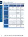
Table of Contents
Safety | 1
Symbols and Notices | 1
Intended Use | 2
Safety Cover | 3
Operating Conditions | 4
Solvents | 4
Replacement Parts | 4
Sécurité | 5
Symboles et avertissements | 5
Utilisation prévue | 6
Capot de protection | 7
Conditions de fonctionnement | 8
Solvants | 8
Pièces détachées | 8

taBLeOFcONteNtS| MINIPULS® 3 PerIStaLtIc PUMP
TABLE OF CONTENTS
CHAPTER 1 | Introduction | 9
Unpacking | 10
Customer Service | 10
Description | 11
Speed Control Module | 12
Front Panel | 12
Rear Panel | 14
Pump Head with Safety Cover | 15
CHAPTER 2 | Setup | 19
Electrical | 20
Remote Control Connections | 20
Install or Change the Pump Head | 23
Remove Cover | 23
Open Pump Head | 24
Install Pump Head | 25
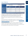
Tubing - Selection and Fitting | 26
Introduction | 26
Type of Material | 27
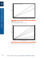
Diameter and Flow Rate | 28
Fitting the Tubing | 29
Safety Cover Installation | 33

MINIPULS® 3 PerIStaLtIc PUMP | USer'S GUIde
TABLE OF CONTENTS
Flow Rate Selection and Adjustment | 33
Selection | 33
Adjustment | 33
Recommendations | 37
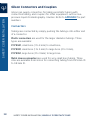
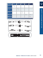
Gilson Connectors and Couplers | 38
Connectors | 38
Coupling Kits | 40
Couplers | 40
CHAPTER 3 | Operation | 41
Keypad Functions | 42
Initialization | 44
Autostart Function | 46
Non-autostart Mode | 46
Autostart Mode | 46
Hold Mode | 46
Mode Selection | 47
Changing the Unit ID | 48
Routine Maintenance | 48
Troubleshooting | 49
Repair and Return Policies | 50
Before Calling Us | 50
Warranty Repair | 50
Non-Warranty Repair | 50
Return Procedure | 51
Unit End-of-Life | 51

taBLeOFcONteNtS| MINIPULS® 3 PerIStaLtIc PUMP
TABLE OF CONTENTS
CHAPTER 4 | Remote Control | 53
Electrical Contact Control | 54
Start/Stop Input (ContactInput) | 54
Direction Control (Contact Input) | 54
Pump Speed (Analog Input) | 55
Control by Gilson Devices | 55
GSIOC Control | 55
GSIOC Commands | 56
Control Modes | 56
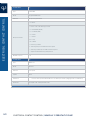
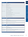
Command Descriptions | 57
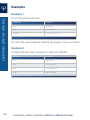
Examples | 62
Example 1 | 62
Example 2 | 62
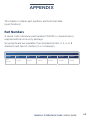
APPENDIX | 63
Part Numbers | 63
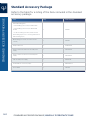
Standard Accessory Package | 64
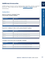
Additional Accessories | 65
Connectors | 65
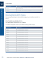
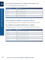
Polyvinylchloride (PVC) Tubing | 66
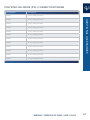
Fluoroelastomer Tubing (Iso-Versinic®/Viton®) | 68
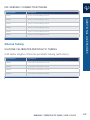
Silicone Tubing | 69
Polypropylene (PharMed®) Tubing | 70
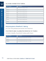
Electrical Connector | 71
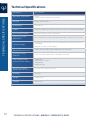
Technical Specifications | 72

Chapter 3 | SaFetY
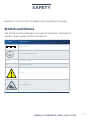
Read this section before installing and operating the pump.
Symbols and Notices
The following internationally recognized electronic and hazard
symbols may appear on the instrument:
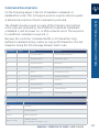
Symbol Explanation
Direct current
Protective conductor terminal
| Electrical power ON
O Electrical power OFF
Caution
Mechanical hazard
1
MINIPULS® 3 PERISTALTIC PUMP | USER'S GUIDE

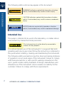
The following safety notices may appear in this document:
WARNING
WARNING indicates a potentially hazardous situation
which, if not avoided, may result in serious injury
CAUTION
CAUTION indicates a potentially hazardous situation
which, if not avoided, may result in minor or moderate
injury
NOTICE
NOTICE indicates a potentially hazardous situation
which, if not avoided, may result in equipment damage
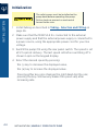
Intended Use
The pump is intended to be used in the laboratory, or similar indoor
environment, by trained technical personnel.
The instrument must not be directly connected to
humans for any purpose.
For safe and proper use of this instrument, it is required that both
operating and service personnel follow the instructions contained in
this guide when installing, cleaning, and maintaining the instrument.
The following safety precautions must be observed during all phases
of operation, service, and repair of the instrument. Failure to comply
with these precautions or with specific warnings elsewhere in this
user’s guide violates safety standards of design, manufacture, and
intended use of the instrument. Gilson assumes no liability for the
customer’s failure to comply with these requirements.
2
INTENDED USE | MINIPULS® 3 PERISTALTIC PUMP
INTENDED USE

The MINIPULS 3 has been certified to safety standards required in
Canada, Europe, and the United States. Refer to the instrument rear
panel label and the Declaration of Conformity document for the
current standards to which the instrument has been found compliant.
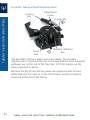
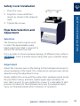
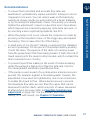
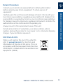
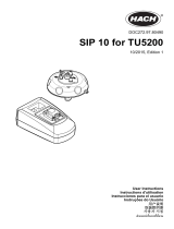
Safety Cover
A safety cover is installed on each pump
head.
The safety cover protects the user from
the mechanical hazard present when the
pump head is rotating.
Do not operate the pump without the
safety cover installed.
Figure 1
R2 Pump Head
with Installed
Safety Cover
3
MINIPULS® 3 PERISTALTIC PUMP | USER'S GUIDE
SAFETY COVER

Operating Conditions
Access to the rear panel is necessary because the instrument must be
detached from all voltage sources before service, repair, or exchange
of parts. Allow a minimum of 2.54 cm (1in.) space behind the
instrument for proper fan operation.
Operate the instrument using the approved power supply provided
and only at the voltage specified on the rear panel label of the
instrument.
Solvents
Observe safe laboratory practices when handling solvents. If
dangerous liquids are used, adequate protection such as proper
ventilation, safety glasses, etc., should be used. Refer to the Material
Safety Data Sheets for the solvents before use.
Replacement Parts
Be sure to use only replacement parts specified in this user’s guide.
Do not repair or change parts which are not listed in this user’s guide.
If it is necessary to change parts not listed, please contact your local
Gilson representative.
4
SOLVENTS | MINIPULS® 3 PERISTALTIC PUMP
SOLVENTS

Chapter 4 | SÉCUrItÉ
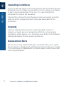
Merci de lire ces instructions avant toute installation ou utilisation de
MINIPULS 3.
Symboles et avertissements
Les symboles suivants sont susceptibles d’apparaître sur l’instrument:
Symbole Signification
Courant continu
Borne de terre de protection
| Sous tension
O Hors tension
Attention
Danger méchanique
5
MINIPULS® 3 PERISTALTIC PUMP | USER'S GUIDE

Les consignes de sécurité suivantes peuvent apparaître dans ce
document:
AVERTISSEMENT
AVERTISSEMENT signale une situation potentiellement
dangereuse qui, si elle n’est pas évitée, peut entraîner
desblessures graves
AT TENTION
ATTENTION signale une situation potentiellement
dangereuse qui, si elle n’est pas évitée, peut entraîner
desblessures mineures ou légères
AVIS
AVIS signale une situation potentiellement
dangereuse qui, si elle n’est pas évitée, peut entraîner
desdommagesmatériels
Utilisation prévue
Cet instrument est destiné à être utilisé dans un environnement de
laboratoire, par un personnel technique qualifié.
AT TENTION
L’instrument ne doit en aucun cas être relié directement
au corps humain.
Pour une utilisation correcte et en toute sécurité, il est nécessaire
que le personnel qui utilise et réalise la maintenance de l’instrument,
suive les instructions contenues dans ce guide lors de l’installation, le
nettoyage et la maintenance de l’instrument.
Les consignes de sécurité suivantes doivent être respectées
durant toutes les phases de fonctionnement, d’entretien ou de
réparation de l’instrument. Le non-respect de ces précautions ou des
avertissements spécifiques mentionnés dans ce guide compromet
les normes de sécurité de conception, de fabrication et d’utilisation
prévue de l’instrument. Gilson décline toute responsabilité en cas
d’’incapacité du client à se conformer à ces exigences.
6
UTILISATION PRÉVUE | MINIPULS® 3 PERISTALTIC PUMP
UTILISATION PRÉVUE

MINIPULS 3 a été certifiée conformément aux normes de sécurité
en vigueur au Canada, en Europe et aux Etats-Unis. Merci de vous
reporter aux indications mentionnées sur le panneau arrière de
l’instrument ainsi qu’au document de Déclaration de Conformité aux
normes pour lesquelles l’instrument a été déclaré conforme.
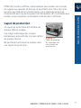
Capot de protection
Un capot de protection est installé sur
chaque tête de pompe.
Il protège l’utilisateur des risques
mécaniques présents dès lors que la tête
de pompe tourne.
Ne pas faire fonctionner la pompe sans
son capot de protection.
Figure 2
Tête de pompe
R2 équipée de
son capot de
protection
7
MINIPULS® 3 PERISTALTIC PUMP | USER'S GUIDE
CAPOT DE PROTECTION

Conditions de fonctionnement
L’accès au panneau arrière doit être libre car l’instrument doit pouvoir
être déconnecté de sa source d’alimentation avant toute opération
d’entretien, de réparation ou de remplacement de pièces.
Ne faîtes fonctionner l’appareil qu’en utilisant le bloc d’alimentation
fourni et uniquement à la tension indiquée sur l’étiquette située à
l’arrière de l’instrument.
Solvants
Respectez les Bonnes Pratiques de Laboratoire lors de la
manipulation de solvants. Si des liquides dangereux sont utilisés,
assurez-vous que la ventilation est adéquate et portez en
permanence un équipement de protection individuelle (EPI), tel que :
lunettes, gants et vêtements de protection.
Reportez-vous aux Fiches de Données de Sécurité pour les solvants
avant toute utilisation.
Pièces détachées
Assurez-vous de n’utiliser exclusivement que les pièces détachées
préconisées dans ce guide. Ne tentez pas de réparer ou remplacer
des pièces ne figurant pas dans ce guide.
Si le remplacement de pièces ne figurant pas dans ce guide s’avérait
nécessaire, merci de contacter votre représentant Gilson local.
8
SOLVANTS | MINIPULS® 3 PERISTALTIC PUMP
SOLVANTS

Chapter 1
CHAPTER 1 | INTRODUCTION
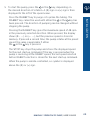
Gilson’s MINIPULS® 3 Peristaltic Pump was specifically designed
to meet process laboratory liquid handling needs. The MINIPULS 3
combines microprocessor speed control with a high-torque stepper
motor. Chemical-resistant pump heads, equipped with five or ten
stainless steel rollers, set the performance standard in producing
smooth, low-pulse flow and reproducible flow rates at higher
pressures.
This user’s guide describes how to set up and operate a MINIPULS 3.
It also describes some of the methodology required to obtain
accurate reproducible results.
IN THIS CHAPTER
• Unpacking on page 10
• Customer Service on page 10
• Description on page 11
• Speed Control Module on page 12
• Pump Head with Safety Cover on page 15
9
MINIPULS® 3 PERISTALTIC PUMP | USER'S GUIDE

Unpacking
Upon receipt of your MINIPULS 3, unpack it and check that all of the
parts are included even if it is not for immediate use. Report any loss
or damage immediately. Keep the original packaging in case the
MINIPULS 3 must be returned to the factory.
After unpacking the box, you should have the following:
• speed control module
• standard accessory package
• external power supply
• documentation
A pump head is required, but ordered separately.
Customer Service
Gilson, Inc. and its worldwide network of authorized representatives
provide customers with the following types of assistance: sales,
technical support, applications, and instrument repair.
If you need assistance, please contact your local Gilson
representative. Specific contact information can be found at www.
gilson.com. To help us serve you quickly and efficiently, please refer
to Repair and Return Policies on page 50.
10
UNPACKING | MINIPULS® 3 PERISTALTIC PUMP
UNPACKING

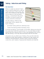
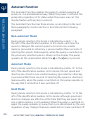
Description
Gilson’s MINIPULS 3 is a peristaltic pump, designed for transferring
fluids with a high level of speed stability and a low pulsation level. It
has many applications, including the following:
• transferring solutions, emulsions, suspensions, and gases at up
to 200°C.
• pumping liquids through chromatographic systems against a
back pressure of up to 0.5 MPa (72.5 psi) when controlled by a
Gilson fraction collector, for example.
• automation of biological analyses by proportionally mixing a
sample with several reagents (flowinjection analysis).
• continuously sampling the components of a production process
(reactors, fermenters, etc.).
• formation of gradients (concentration, pH, etc.).
Control of the MINIPULS 3 is from a computer via GSIOC and Gilson
TRILUTION® LH software, remote control by contact closure, or
manual control by front panel operation.
11
MINIPULS® 3 PERISTALTIC PUMP | USER'S GUIDE
DESCRIPTION

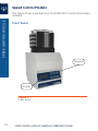
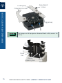
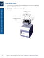
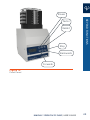
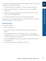
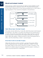
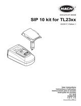
Speed Control Module
The figure shows a general view of a MINIPULS 3, before the head is
installed.
Front Panel
Display
Keypad
Figure 3
Front Panel
12
SPEED CONTROL MODULE | MINIPULS® 3 PERISTALTIC PUMP
SPEED CONTROL MODULE

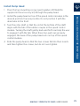
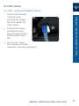
The front panel consists of:
• a keypad
• Slower - Decrease the pumpspeed
• Faster - Increase the pumpspeed
• Rabbit - Set speed to 48 rpm for priming
• Forwards - Start the pump clockwise
• Backwards - Start the pump counter-clockwise
• Stop - Stop the pump
• a display
13
MINIPULS® 3 PERISTALTIC PUMP | USER'S GUIDE
SPEED CONTROL MODULE

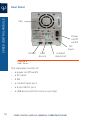
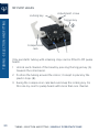
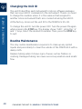
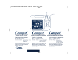
Rear Panel
GSIOC
Fan
Power
on/o
switch
Contact
input port
DC
input
USB
device
Figure 4
Rear Panel
The rear panel consists of:
• a power on/off switch
• a DC input
• a fan
• a contact input port
• a 9-pin GSIOC port
• a USB device port (for service use only)
14
SPEED CONTROL MODULE | MINIPULS® 3 PERISTALTIC PUMP
SPEED CONTROL MODULE
La page est en cours de chargement...
La page est en cours de chargement...
La page est en cours de chargement...
La page est en cours de chargement...
La page est en cours de chargement...
La page est en cours de chargement...
La page est en cours de chargement...
La page est en cours de chargement...
La page est en cours de chargement...
La page est en cours de chargement...
La page est en cours de chargement...
La page est en cours de chargement...
La page est en cours de chargement...
La page est en cours de chargement...
La page est en cours de chargement...
La page est en cours de chargement...
La page est en cours de chargement...
La page est en cours de chargement...
La page est en cours de chargement...
La page est en cours de chargement...
La page est en cours de chargement...
La page est en cours de chargement...
La page est en cours de chargement...
La page est en cours de chargement...
La page est en cours de chargement...
La page est en cours de chargement...
La page est en cours de chargement...
La page est en cours de chargement...
La page est en cours de chargement...
La page est en cours de chargement...
La page est en cours de chargement...
La page est en cours de chargement...
La page est en cours de chargement...
La page est en cours de chargement...
La page est en cours de chargement...
La page est en cours de chargement...
La page est en cours de chargement...
La page est en cours de chargement...
La page est en cours de chargement...
La page est en cours de chargement...
La page est en cours de chargement...
La page est en cours de chargement...
La page est en cours de chargement...
La page est en cours de chargement...
La page est en cours de chargement...
La page est en cours de chargement...
La page est en cours de chargement...
La page est en cours de chargement...
La page est en cours de chargement...
La page est en cours de chargement...
La page est en cours de chargement...
La page est en cours de chargement...
La page est en cours de chargement...
La page est en cours de chargement...
La page est en cours de chargement...
La page est en cours de chargement...
La page est en cours de chargement...
La page est en cours de chargement...
La page est en cours de chargement...
La page est en cours de chargement...
-
 1
1
-
 2
2
-
 3
3
-
 4
4
-
 5
5
-
 6
6
-
 7
7
-
 8
8
-
 9
9
-
 10
10
-
 11
11
-
 12
12
-
 13
13
-
 14
14
-
 15
15
-
 16
16
-
 17
17
-
 18
18
-
 19
19
-
 20
20
-
 21
21
-
 22
22
-
 23
23
-
 24
24
-
 25
25
-
 26
26
-
 27
27
-
 28
28
-
 29
29
-
 30
30
-
 31
31
-
 32
32
-
 33
33
-
 34
34
-
 35
35
-
 36
36
-
 37
37
-
 38
38
-
 39
39
-
 40
40
-
 41
41
-
 42
42
-
 43
43
-
 44
44
-
 45
45
-
 46
46
-
 47
47
-
 48
48
-
 49
49
-
 50
50
-
 51
51
-
 52
52
-
 53
53
-
 54
54
-
 55
55
-
 56
56
-
 57
57
-
 58
58
-
 59
59
-
 60
60
-
 61
61
-
 62
62
-
 63
63
-
 64
64
-
 65
65
-
 66
66
-
 67
67
-
 68
68
-
 69
69
-
 70
70
-
 71
71
-
 72
72
-
 73
73
-
 74
74
-
 75
75
-
 76
76
-
 77
77
-
 78
78
-
 79
79
-
 80
80


dans d''autres langues
- English: Gilson Minipuls 3 User manual
Documents connexes
Autres documents
-
 Hach TPM870 Manuel utilisateur
-
CTX MyPOOL Series Operating
-
US Water Stenner Series SVP Manuel utilisateur
-
 Hach Lachat QuikChem Manuel utilisateur
-
 Hach SIP 10 User Instructions
-
Buhler RC 1.1 Quick Manual
-
 Hach SIP 10 kit User Instructions
-
Franklin Electric 553676 Guide d'installation
-
 Compat DualFlo 199255 Mode d'emploi
-
lbx instruments LBX P10 Manuel utilisateur


