Metrologic MS700i Installation and User Manual
- Catégorie
- Lecteurs de codes à barres
- Taper
- Installation and User Manual

MS700i Series Laser Bar
Code Projection Scanner
Installation and User’s Guide
MLPN 2178
Printed in USA
October 1998

iii
Table of Contents
Introduction .................................................. 1
Unpacking List ................................................. 2
Scanner Connections to the Host ................................... 3
Configuration of the Scanner to the Host System ...................... 4
Cloning Feature ................................................ 5
Version 11 IBM 46XX Scanner ................................... 6
Configuring the Scanner .................................. 7
Configuring the IBM 46XX ............................... 8
IBM 4683 and 4693 Terminals Driven by a 46XX Store
Controller Running 4680.OS or 4690.OS ............ 8
IBM 4684 and 4694 Systems .............................. 8
Scanner Installation to a PC Keyboard Port ....................... 9, 10
PC Application Note ........................................... 11
Installation of the MS700 Series Stand ............................. 12
Attaching the Scanner to the Stand ................................ 13
MS700i and MS720i Features ................................... 14
Visual Indicators ........................................... 15-18
Volume Settings ............................................... 19
Labels ....................................................... 20
InfraRed (IR) Object Sensor ..................................... 21
Symbol Orientation ............................................ 22
Active Scan Region for the MS700i and MS715i Scanner ............. 23
Horizontal Scan Width vs. Distance for the MS700i and MS715i Scanner . 24

iv
Active Scan Region for the MS720i Scanner ........................ 25
Horizontal Scan Width vs. Distance for the MS720i Scanner ........... 26
Depth of Field for the MS700i and MS715i Scanner .................. 27
Depth of Field and Symbol Specification for the MS700i and MS715i . 28, 29
Depth of Field for the MS720i Scanner ............................ 30
Depth of Field and Symbol Specification for the MS720i ........... 31, 32
Maintenance .................................................. 33
Applications and Protocols ...................................... 33
Appendix A
Specifications ...................................... 34, 35
Appendix B
Default Settings ..................................... 36-41
Appendix C
Pin Assignments .................................... 42-46
Appendix D
Warranty and Disclaimer ............................. 47, 48
Appendix E
Notices ........................................... 49, 50
Appendix F
Patents ............................................... 51
Volume Control Card ....................................... 52, 53
Index .................................................... 53, 54

1
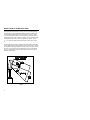
Introduction
The MS700i Series Scanners are high throughput projection scanners that
incorporate the latest in VLD (Visible Laser Diode) ASIC/VLSI and surface
mount technologies. Each scanner consumes only 8 watts of power and can
directly connect to many host systems that can support a scanning device. One
thoughtful feature is a “sleep mode” that turns the laser and motor off when not
in use. Other features include easy-to-see LED indicators that can be viewed
from the top or front and a volume control card that can be scanned to control
volume levels. There are two programming methods: through the
ScanSelect™ programming guide or through ScanSet™ (an IBM PC
compatible software program.)
With a scan speed of 2,000 lines per second, these scanners aggressively scan
poorly printed bar codes and read torn and bent UPC, EAN and JAN bar
codes immediately on the first pass at any roll angle. For close scanning, the
MS700i and MS715i’s depth of field of 0.0mm - 178mm (0" - 7") is ideal. To
accommodate applications where scanning items farther away from the scan
window is preferred, the MS720i’s depth of field of 178mm - 381mm (7" -
15") is ideal.

2
Unpacking List
The shipping carton should contain the following:
! Installation and User’s Guide (MLPN: 2178)
! ScanSelect™ Scanner Programming Guide (MLPN: 2186)
! Volume Control Card (MLPN: 2346)
! MS700i /MS715i or MS720i Laser Bar Code Projection Scanner
! Power Supply (optional)
! Communication cable with connection for power supply (optional) or
Communication Cable (optional)
! Stand #45483 (optional)

3
Scanner Connections to the Host
To maintain compliance with applicable standards, all circuits connected to the
scanner must meet the requirements for SELV (Safety Extra Low Voltage)
according to EN 60950. To avoid potential problems, do not power up the
scanner until the communication cable is secured to the host.
1. Turn off the host system.
2. Connect the 25-pin D-type connector on the scanner’s head cable to the
communication cable. Connect the other end of the communication
cable to the host device. (If the scanner will not receive power from a
transformer, skip to Step 5.)
3. If the scanner will receive power from an external power source, check
the AC input requirements of the transformer to make sure the voltage
matches the AC outlet. (A socket-outlet can be installed near the
equipment so it will be easily accessible.)
4. Plug the transformer into the side of the female D-type connector
located on the communication cable. Plug the transformer into the AC
outlet to supply power to the scanner.
5. Power up the host system.
Note: When the scanner first receives power, the LEDs will flash and
then the scanner will beep once. After the scanner performs this
startup sequence, the green LED will remain on for a specified
time indicating that the laser is on.

4
Configuration of the Scanner to the Host System
The scanner is shipped from the factory programmed to a set of default
conditions. These default conditions are in the Default Settings section of this
guide pages 36-41 and in the ScanSelect™ Scanner Programming Guide. The
default settings in the ScanSelect guide have an asterisk that appears before
the brief definition next to the bar code.
For the scanner to properly communicate with the host system, it needs to be
programmed to meet the specific scanning needs. Since each host system is
unique, configure the scanner to match the host system requirements.
Configure the scanner by entering program mode and scanning the appropriate
bar codes that appear in the ScanSelect Scanner Programming Guide. (When
using ScanSet™, refer to the ScanSet documentation for information on how
to configure the scanner.)
1. Connect the scanner to the host system (Refer to the Scanner
Connections to the Host section in this guide).
2. Enter program mode by scanning the ENTER/EXIT program mode bar
code as the first bar code after a power up cycle. (The unit will beep
three times)
3. Scan the appropriate bar code(s) that appear in the ScanSelect Scanner
Programming Guide. (Reveal only one bar code to the scanner each
time. With your hand, cover the bar code that is not to be scanned.)
4. Exit program mode by scanning the ENTER/EXIT program mode bar
code again. (The new options will be saved and the scanner is ready for
normal operation.)
Note: Non-RS-232 interfaces chosen in Section B of the ScanSelect
Programming Guide do not match the default settings loaded when
the same interface is selected with ScanSet.

5
CLONING
Cloning Feature
To program several scanners with the same settings, use the Cloning feature.
This is done by connecting the cloning cable (MLPN: #51544) between two
scanners.
1. Turn off both scanners.
2. Connect the cloning cable between the two scanners.
3. Turn both scanners on by plugging in the transformers.
4. Once each scanner is ready, scan the cloning bar code with the scanner
that has the settings that need to be transferred to the other scanner.

6
Version 11 IBM 46XX Scanner
Output Format: IBM RS-485 serial input/output for the 4680 and 4690
(46XX) point-of-sale terminals
The Version 11 46XX interface can be used in several different ways. Both the
46XX terminal and the scanner must be configured to match each other.
Warning: Power to the scanner and 46XX terminal should be turned off
before making physical connection.
The 4680 and 4690 series terminals have different types of physical ports for
connecting bar code scanners. Scanner ports include Port 5B, Port 17, and
Port 9? (? = A, B, C, or E). A Port 9 type connector is present on all versions
of the 46XX families of terminals. That is one reason it is the normal point of
connection for Metrologic scanners. Another reason is that there is enough 12
volt power available to operate many Metrologic scanners. If the terminal
configuration requires use of a different physical port for connecting bar code
scanners, contact Metrologic to get particular adaptor cable information.
No matter what port is in use for the physical connection, all devices use a
common communications bus inside the 46XX terminal. Each device uses a
different address when it must communicate. The terminal must be configured
to look for a device at a logical address.
The IBM 1520 mode/address was selected as a default because it was the first
IBM 46XX family scanner to support UPC/EAN, Code 39 and Interleaved 2
of 5. The Version 11 scanner formats Codabar, Code 128, and Code 93 using
the Code 39 function code designation supported by the IBM device driver for
this scanner type. Other emulation modes currently available are the IBM
3687-2 Port 17 fixed scanner and the Port 9B IBM 4500 CCD hand-held bar
code reader. One of these other emulation modes may be needed depending on
which operating system (4680.OS, 4690.OS, POS/DOS or DOS/RIPPS) is in
use at the site.
Note: The IBM 4683 and IBM 4684 terminals have a good proven track
record of supplying power to Metrologic scanners. The IBM 4693
and IBM 4694 terminals may be restricted from supplying power to
certain scanner models. Specifically, Metrologic currently
recommends using an external power supply for the scanner when
connecting to an IBM 4694. Metrologic has no recommendations at
this time for IBM 4693 terminals.

7
Configuring the Scanner
Located in the Version 11 scanner are two computer boards. One board is for
decoding and the other for 46XX IO processing. The decode board is
configured using ScanSet™ or ScanSelect™ while the IO board is configured
with an internal DIP Switch bank.
For UPC/EAN scanning, the decode board should be set as follows:
Enable IBM 4680 Communication
Enable UPC/EAN
Beep after Transmit
Enable Communication Timeouts
Transmit UPC-A Check Digit
Transmit UPC-E Check Digit
These settings configure the decode board to beep after transmitting the data to
the terminal device driver. If the data does not clear the communications buffer
within two seconds, it is discarded without giving the operator a good scan
indication. This accommodates newer versions of the IBM device drivers that
enable/disable scanning in many different situations.
The default setting of the interface board is to emulate the IBM 1520 hand
scanner that supports UPC/EAN and alphanumeric code types. The following
is a list of switch settings for the internal interface board that handles the
46XX SIOC communications.
There are eight DIP switches on the board that are both software and hardware
switches.
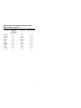
Switch 1 Switch 2 Emulation Mode
OFF OFF Port 5B, IBM 1520 Model 2 Laser Scanner
(default setting)
OFF ON Port 9B, CCD (IBM 4500/Opticon)
ON OFF Port 17, IBM 4014 Adaptor for 3687-2 to 468X
ON ON Reserved
Switch 3 Reserved (Should be OFF)
Switches 4, 5, 6, and 7 Must be ON
Switch 8 Should be OFF (Reserved)

8
Configuring the IBM 46XX
The 4683 and 4693 terminals are configured on the store controller. The 4684
and 4694 terminals are typically configured on the individual terminals.
Follow the appropriate guide for the type of equipment.
IBM 4683 and 4693 Terminals Driven by a 46XX Store Controller
Running 4680.OS or 4690.OS
Access the terminal configuration menu on the store controller. If not already
selected, select an IBM 1520 laser hand scanner (4680.OS Port 5B), an IBM
4500 hand-held bar code reader (CCD, 4680.OS Port 9B), or an IBM 3687-2
fixed scanner (4680.OS Port 17) that matches the configuration of the scanner.
Regarding the 4690.OS, at the time of this printing, Metrologic does not know
exactly which terminal port configuration screen is used for selecting scanners.
It should be listed under the Port 9A, 9B, 9C, or 9E sections. The 4693
terminal has a Port 5B that was originally used for the IBM 1520 scanner.
While IBM has withdrawn this product, it was not clear how terminal
configuration and device driver support would be provided for the installed
base of users.
Save the configuration and activate it for the desired terminals. Download the
configuration to the terminal(s) per standard procedures.
IBM 4684 and 4694 Systems
Initialize the RIPPS drivers for a hand scanner if hand scanner emulation was
selected. Initialize the RIPPS drivers for a "POS scanner" if the 3687-2
scanner has been selected.

9
Scanner Installation to a PC Keyboard Port
The MS700i/MS715i/MS720i/ scanner (version 17) provides keyboard
emulation by converting the scanned bar code data to the PC keyboard scan
code equivalent. The following are the supported keyboard and country types:
PC Type
! AT (includes IBM PS/2 and compatible models 50, 55, 60, 80)
®
! XT
! PS/2 (includes IBM PC and compatible models 30, 70, 8556)
Keyboard Country Type
! USA ! United Kingdom
! France ! Germany
! Italy ! Spain
! Belgium ! Swiss
The communication cable kit (MLPN: 45927) has a communication cable
with one (1) 5 Pos female DIN connector and one (1) 6 Pos male mini DIN
connector. The kit also includes an adaptor cable. This cable allows the
scanner to plug into an IBM PC XT or AT compatible computer or a PS/2
®
computer and keyboard.
With the appropriate communication cable, the scanner will also provide RS-
232 or light pen emulation interface. When configuring the scanner for one
interface versus another, change all necessary parameters for that particular
interface. For instance, to configure the scanner for keyboard wedge emulation,
recall defaults, select the PC type, keyboard country type and intercharacter
delay. For further information, refer to the ScanSelect™ Scanner Programming
Guide or ScanSet™ Scanner Configuration Guide.

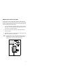
10
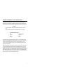
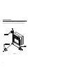
Figure 1
To maintain compliance with applicable standards, all circuits connected to the
scanner must meet the requirements for SELV (Safety Extra Low Voltage)
according to EN 60950.
1. When connecting to
a PS/2 computer,
attach to the com-
munication cable
(#51573) the 5M 6F
adaptor to the
female connector
and the 5F 6M
adaptor to the male
connector.
2. If the PC is on, exit
the application and
turn the PC off.
3. Disconnect the keyboard from the PC.
4. Plug the communication cable to the PC and the keyboard.
(Refer to Figure 1).
5. Connect the 25-pin D-type connector on the scanner’s head cable to the
communication cable.
6. Check the AC input requirements of the transformer to make sure the
voltage matches the AC outlet.
(A socket-outlet shall be installed near the equipment and shall be
easily accessible.)
7. Plug the transformer into the side of the female D-type connector
located on the communication cable. Plug the transformer into the AC
outlet to supply power to the scanner.
8. Turn the PC on.

11
PC Application Note:
For most applications, it will be desirable to disable linefeed transmission. For
non-USA keyboards, 10 mesc is probably the best intercharacter delay.
Network system installations, may require tuning of the intercharacter and
inter scan code options.
Note:
Once the scanner connects to the PC, the PC can be turned on and will operate
normally even if the scanner's transformer plug is not in. How-
ever, bar codes will not be read until the scanner receives power. When
the scanner first receives power, the LEDs will flash and then the scanner
will beep once. After the scanner performs this startup sequence, the
green LED will remain on for a specified time indicating the laser is on.

12
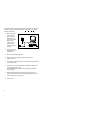
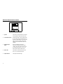
Figure 2
Installation of the MS700 Series Stand
The following are components used to build the MS700 Series stand
(MLPN: 45483):
1 Shoe Mount 4 Four Wood Screws
2 Stand Cover 5 One Machine (¼-20) Screw
3 Stand Base 6 Internal Lock Washer
7 Flexible Shaft
1. Use the 2½ inch x 2½ inch stand base to mark the position for pilot
holes.
2. Use the four wood screws to secure the base to the work surface.
3. Position the stand cover on top of the stand base.
4. Screw the flexible shaft to the stand base.
5. Place the internal lock washer on top of the flexible shaft and then
screw the shoe to the shaft with the machine screw.

13
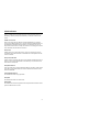
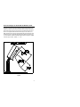
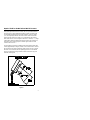
Figure 3
Attaching the Scanner to the Stand
Once the stand is securely mounted to the work surface, attach the scanner.
The scanner has a “foot” that is at the bottom of the scanner. This foot fits into
the “shoe” attached to the top of the stand. This construction helps prevent the
scanner from being knocked from the stand.
1. To prevent obstruction when sliding the scanner into place, loosen the
small screw (A) located in the center of the long part of the shoe with a
3/32" hex key wrench. (Refer to Figure 3)
2. Align the foot of the scanner with the shoe of the stand and slide the
scanner into position.
3. Tighten the small screw (A) located at the center of the long part of the
shoe. This screw holds the scanner in place.
Note: Fasten the stand to the work surface before adjusting the angle of
the flexible shaft. To adjust the angle, firmly hold the shaft and
push the shaft to a north, south, east, or west direction.

14
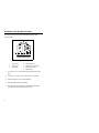
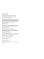
Figure 4
MS700i and MS720i Series Features
1 Speaker The sound of a beep emits from here when the
scanner performs a good read of a bar code.
2 Green and Red LEDs When the green LED is on, this indicates that
the unit is receiving power and the laser is on.
When the red LED flashes on, the scanner has
read a bar code successfully. When the red
light turns off, communication to the host is
complete.
3 InfraRed Object When a specified time has elapsed
Sensor without any scanning, the unit will enter a
“standby” mode. The scanner will not return
to scanning until an object or a wave your
hand is passed in front of the IR sensor.
4 Head Cable This cable can connect directly to the host
device or to a communication cable.
5 Output Window This aperture emits laser light.

15
Visual Indicators
There is a red LED and a green LED located on the scanner. When the scanner is on,
the flashing or stationary activity of the LEDs alert you to the status of the scan and
scanner.
No Red or Green LED
There are two reasons why the LEDs will not be illuminated. First, if the scanner is
receiving power and the LEDs are not on, then the scanner has remained dormant for a
specified period of time and the laser has turned off. To reactivate the unit, wave an
object in front of the IR sensor. Secondly, if the scanner is not receiving power from the
host or transformer, then the LEDs will not turn on.
Steady Green
When the laser is on, the green LED is also on. This occurs when an object is in the
scan field. The green LED will remain on until the IR time-out has elapsed or until the
scanner is turned off.
Steady Green; Red Flash
When the scanner successfully reads a bar code, the red LED will flash followed by one
beep. If you do not see the red LED flash or the scanner beep once, then the bar code
has not been successfully read.
Steady Red and Green
After a successful scan, the scanner transmits the data to the host device. When the host
is not ready to accept the information, the scanner’s red LED will remain on until the
data can be transmitted.
Alternating Red and Green
This indicates the scanner is in program mode.
Steady Red
This indicates the scanner is in ScanSet mode.
Flashing Red
This indicates the scanner has experienced a laser subsystem failure. Return the unit for
repair at an authorized service center.

16
Signaux optiques
Sur la partie supérieure du scanner se trouvent une diode LED rouge et une diode LED
verte. Quand le scanner est sous tension, les diodes rouge et verte clignotantes ou
allumées vous informent sur l'état du scanner.
Ni la diode rouge, ni la diode verte n'est allumée
Il existe deux raisons possibles pour que les diodes ne s'allument pas. Premièrement: si
le scanner reçoit de l'énergie sans que les diodes ne s'allument, le scanner est resté sans
servir pendant une certaine période et le laser est désactivé. Pour le réactiver, passer un
objet devant le palpeur infrarouge. Deuxièmement: quand le scanner ne reçoit de
l'énergie ni de l'ordinateur central, ni du transformateur, les diodes restent éteintes.
La diode verte reste allumée
Quand le laser est en service, la diode verte s'allume également. C'est le cas quand un
objet se trouve devant le palpeur. La diode verte reste allumée tant que la temporisation
de l'infrarouge dure ou jusqu'à ce que le scanner soit désactivé.
La diode verte reste allumée; la diode rouge clignote
Après lecture avec succès d'un code à barres par le scanner, la diode rouge se met à
clignoter, suivie d'un bip sonore unique. Si la diode rouge ne clignote pas ou quand
aucun bip sonore n'est émis, cela signifie que le code à barres n'a pas pu être lu avec
succès.
Les diodes rouges et vertes restent allumées
Une fois la lecture effectuée avec succès, le scanner transmet les données à l'ordinateur
central. Si ce dernier n'est pas prêt à recevoir les données, la diode rouge du scanner
reste allumée jusqu'à ce que les données puissent être transmises.
Les diodes rouges et vertes clignotent en alternance
Indique que le scanner se trouve en mode de programmation.
La diode rouge reste allumée
Indique que le scanner se trouve en mode ScanSet.
Diode rouge clignotante
Indique une panne de laser pendant la lecture. Veuillez envoyer votre appareil chez un
concessionnaire pour réparation.

17
Optische Anzeigen
Auf dem Scanner befinden sich eine rote und eine grüne Leuchtdiode. Bei
eingeschaltetem Scanner geben Ihnen die blinkenden bzw. feststehenden
Leuchtdiodenanzeigen Aufschluß über den Abtast- und Scannerstatus.
Weder rote noch grüne Leuchtdiodenanzeige
Es gibt zwei mögliche Gründe, weshalb die Leuchtdiodenanzeigen nicht aufleuchten.
Erstens: Wenn der Scanner mit Energie versorgt wird und die Leuchtdiodenanzeigen
nicht aufleuchten, so ist der Scanner für einen bestimmten Zeitraum untätig geblieben,
und der Laser ist abgeschaltet. Zur Reaktivierung der Einheit sollten Sie ein Objekt vor
dem Infrarot-Sensor hin- und herbewegen. Zweitens: Wenn der Scanner weder vom
Hostrechner noch vom Transformator Energie erhält, so leuchten die
Leuchtdiodenanzeigen nicht auf.
Feststehende grüne Anzeige
Wenn der Laser in Betrieb ist, leuchtet die grüne Leuchtdiodenanzeige ebenfalls auf.
Dies ist dann der Fall, wenn sich ein Objekt im Abtastfeld befindet. Die grüne
Leuchtdiodenanzeige leuchtet solange auf, bis das Infrarot-Timeout abgelaufen ist, oder
bis der Scanner abgeschaltet wird.
Feststehende grüne Leuchtanzeige; rote Blinkanzeige
Nach erfolgreichem Lesen eines Barcodes durch den Scanner blinkt die rote
Leuchtdiodenanzeige auf, gefolgt von einem einmaligen Piep-Signal. Blinkt die rote
Leuchtdiodenanzeige nicht auf oder sendet der Scanner kein Piep-Signal aus, so konnte
der Barcode nicht erfolgreich gelesen werden.
Feststehende rote und grüne Leuchtanzeige
Nach erfolgreichem Abtasten überträgt der Scanner die Daten an das Hostgerät. Falls
das Hostgerät zur Datenannahme nicht bereit ist, leuchtet die rote Leuchtdiodenanzeige
des Scanners solange auf, bis die Daten übertragen werden können.
Alternierende rote und grüne Leuchtanzeige
Zeigt an, daß sich der Scanner im Programmiermodus befindet.
Feststehende rote Leuchtanzeige
Zeigt an, daß sich der Scanner im ScanSet-Modus befindet.
Aufblinkende rote Leuchtanzeige
Zeigt an, daß beim Scanner ein Laserausfall vorliegt. Bringen Sie das Gerät zur Reparatur in ein
Vertragsservicecenter.
La page est en cours de chargement...
La page est en cours de chargement...
La page est en cours de chargement...
La page est en cours de chargement...
La page est en cours de chargement...
La page est en cours de chargement...
La page est en cours de chargement...
La page est en cours de chargement...
La page est en cours de chargement...
La page est en cours de chargement...
La page est en cours de chargement...
La page est en cours de chargement...
La page est en cours de chargement...
La page est en cours de chargement...
La page est en cours de chargement...
La page est en cours de chargement...
La page est en cours de chargement...
La page est en cours de chargement...
La page est en cours de chargement...
La page est en cours de chargement...
La page est en cours de chargement...
La page est en cours de chargement...
La page est en cours de chargement...
La page est en cours de chargement...
La page est en cours de chargement...
La page est en cours de chargement...
La page est en cours de chargement...
La page est en cours de chargement...
La page est en cours de chargement...
La page est en cours de chargement...
La page est en cours de chargement...
La page est en cours de chargement...
La page est en cours de chargement...
La page est en cours de chargement...
La page est en cours de chargement...
La page est en cours de chargement...
La page est en cours de chargement...
-
 1
1
-
 2
2
-
 3
3
-
 4
4
-
 5
5
-
 6
6
-
 7
7
-
 8
8
-
 9
9
-
 10
10
-
 11
11
-
 12
12
-
 13
13
-
 14
14
-
 15
15
-
 16
16
-
 17
17
-
 18
18
-
 19
19
-
 20
20
-
 21
21
-
 22
22
-
 23
23
-
 24
24
-
 25
25
-
 26
26
-
 27
27
-
 28
28
-
 29
29
-
 30
30
-
 31
31
-
 32
32
-
 33
33
-
 34
34
-
 35
35
-
 36
36
-
 37
37
-
 38
38
-
 39
39
-
 40
40
-
 41
41
-
 42
42
-
 43
43
-
 44
44
-
 45
45
-
 46
46
-
 47
47
-
 48
48
-
 49
49
-
 50
50
-
 51
51
-
 52
52
-
 53
53
-
 54
54
-
 55
55
-
 56
56
-
 57
57


Metrologic MS700i Installation and User Manual
- Catégorie
- Lecteurs de codes à barres
- Taper
- Installation and User Manual
dans d''autres langues
- italiano: Metrologic MS700i
- English: Metrologic MS700i
Documents connexes
-
Metrologic IS421X ScanGlove Mode d'emploi
-
-
Metrologic TECH 7 MS770 Installation and User Manual
-
-
-
-
-
-
-
Autres documents
-
Metrologic Instruments MLPN 2159 Manuel utilisateur
-
-
Posiflex TS-2200 Manuel utilisateur
-
Motorola LS1203 Quick Reference Manual
-
Datalogic Laptop DLL2020-WO Manuel utilisateur
-
König CMP-BARSCAN21 spécification
-
NCR All in One Printer 7882 Manuel utilisateur
-
-
Konig Electronic CMP-BARSCAN40 Manuel utilisateur
-
Intermec Sabre 1551B Quick Reference Manual