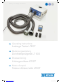
Lindab LTEST Operating Instructions Manual
- Catégorie
- Mesure
- Taper
- Operating Instructions Manual


2
EN
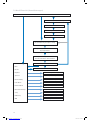
Contents
1 Description ............................. 4
2 Technical data .......................... 4
3 Controls ............................... 5
4 Test principle ........................... 5
5 Preparing a duct system for testing ......... 6
6 Test sequence .......................... 7
7 Using for the first time, and performing a test . 7
7.1 Control panel functions ................... 7
7.2 Menu description ........................ 8
7.3 First test ............................... 9
8 Expert mode .......................... 11
9 Messages ............................ 11
10 Main menu ............................ 12
10.1 Print ................................. 12
10.2 Chart ................................ 12
10.3 Save ................................. 12
10.4 Data admin ............................ 13
10.5 Laboratory mode ....................... 14
10.6 Custom airtightness class ................ 14
10.7 Differential pressure .................... 14
10.8 Setup ................................ 15
10.9 Units of measurement ................... 15
10.10 Calibration ............................ 15
10.11 Info .................................. 16
11 Content of report printout ................ 16
12 Software. . . . . . . . . . . . . . . . . . . . . . . . . . . . . . 17
13 Operation and maintenance .............. 17
14 Package contents ...................... 18
15 Available accessories and consumables .... 18
16 Declaration of conformity ................ 18
17 Warranty and service .................... 19
18 Appendix ............................. 20
DE
Inhaltsverzeichnis
1 Anwendungsbeschreibung ............... 22
2 Techn. Daten .......................... 22
3 Bedienelemente ........................ 23
4 Messprinzip ........................... 23
5 Vorbereitung eines zu prüfenden
Luftleitungssystems ..................... 24
6 Testablauf ............................ 25
7 Erste Inbetriebnahme und Durchführung
einer Messung ......................... 25
7.1 Bedienfeld-Funktionen .................. 25
7.2 Menü-Übersicht ........................ 26
7.3 Messung ............................. 27
8 Experten-Modus ....................... 29
9 Hinweismeldungen ..................... 29
10 Hauptmenü ........................... 30
10.1 Drucken .............................. 30
10.2 Diagramm ............................ 30
10.3 Speichern ............................. 30
10.4 Datenverwaltung ....................... 31
10.5 Labor-Modus .......................... 32
10.6 Benutzerdefinierte Dichtheitsklasse ........ 32
10.7 Differenzdruckanzeige ................... 32
10.8 Setup ................................ 33
10.9 Einheiten ............................. 33
10.10 Kalibrierung ........................... 33
10.11 Info .................................. 34
11 Inhalt des Protokoll-Ausdrucks ............ 34
12 Software. . . . . . . . . . . . . . . . . . . . . . . . . . . . . . 35
13 Betrieb und Wartung .................... 35
14 Lieferumfang .......................... 36
15 Erhältliches Sonderzubehör und Ver-
brauchsmaterial ........................ 36
16 Konformitätserklärung ................... 36
17 Gewährleistung und Service .............. 37
18 Anhang ............................... 38
manual-LTEST-1082_EN-DE-FR-SE.indd 2 2012-03-28 12:32:35

3
FR
Table des matières
1 Domaine d'application ................... 58
2 Caractéristiques techniques .............. 58
3 Organes de commande .................. 59
4 Principe de mesure ..................... 59
5 Préparation du réseau aéraulique à tester ... 60
6 Déroulement du test .................... 61
7 Première utilisation et réalisation d'une
mesure ............................... 61
7.1 Fonctions du panneau de commande ...... 61
7.2 Présentation des menus ................. 62
7.3 Mesure ............................... 63
8 Mode Expert .......................... 65
9 Messages d'avertissement ............... 65
10 Menu principal ......................... 66
10.1 Imprimer .............................. 66
10.2 Diagramme ........................... 66
10.3 Enregistrer ............................ 66
10.4 Gestion des données ................... 67
10.5 Mode Laboratoire ...................... 68
10.6 Classe d'étanchéité définie par l'utilisateur ...68
10.7 Affichage de la pression différentielle ....... 68
10.8 Configuration .......................... 69
10.9 Unités ................................ 69
10.10 Étalonnage ............................69
10.11 Informations ........................... 70
11 Contenu d'un protocole imprimé ........... 70
12 Logiciel ............................... 71
13 Utilisation et maintenance ................ 71
14 Contenu de la livraison .................. 72
15 Accessoires disponibles et consommables .. 72
16 Déclaration de conformité ................ 72
17 Garantie et service après-vente ........... 73
18 Annexe ............................... 74
SE
Innehållsförteckning
1 Användningsområde .................... 40
2 Tekn. data ............................ 40
3 Manöverelement ....................... 41
4 Mätprincip ............................ 41
5 Förberedelse av luftkanalsystem som ska
testas ................................ 42
6 Testmetod ............................ 43
7 Första idrifttagning och genomförande av
en mätning ............................ 43
7.1 Manöverfunktioner ..................... 43
7.2 Menyöversikt .......................... 44
7.3 Mätning .............................. 45
8 Expertläge ............................ 47
9 Informationsmeddelanden ............... 47
10 Huvudmeny ........................... 48
10.1 Utskrift ............................... 48
10.2 Diagram .............................. 48
10.3 Lagring ............................... 48
10.4 Datahantering ......................... 49
10.5 Laboratorieläge ........................ 49
10.6 Manuellt definierad täthetsklass ........... 50
10.7 Differenstryckvisning .................... 50
10.8 Konfigurering .......................... 51
10.9 Enheter ............................... 51
10.10 Kalibrering ............................ 51
10.11 Info .................................. 52
11 Innehåll i protokollutskrift ................ 52
12 Programvara .......................... 53
13 Drift och underhåll ...................... 53
14 Leveransomfattning ..................... 54
15 Tillbehör och förbrukningsmaterial ......... 54
16 Konformitetsförsäkran ................... 54
17 Garanti och service ..................... 55
18 Bilaga ................................ 56
manual-LTEST-1082_EN-DE-FR-SE.indd 3 2012-03-28 12:32:35

4
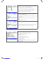
1. Description
• The Lindab leakage tester is designed to verify the
airtightness of duct systems, but can also be used
to test other enclosures (air conditioning units, cli-
mate chambers, electrical cabinets, furnaces, etc.).
• The device measures the flow rate that is necessary
in order to maintain the selected test pressure in an
enclosed system.
• The device uses a membrane keypad and an OLED
colour display to operate a menu-drive interface.
• The test results can be sent to a local thermal printer
(included) via a wireless infrared interface.
• The device can permanently store data, define cus-
tomers and measuring points, and transfer data to a
computer via a USB interface.
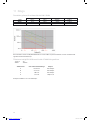
Airtightness class
DIN EN 13779
Airtightness class
in
EUROVENT 2/2
Airtightness class
in
DIN 24194 Part 2
Limit value for
leakage flow rate (fmax)
m³ s-1m-2
A A II 0.027 x pt0.65 x 10-3
B B III 0.009 x pt0.65 x 10-3
C C IV 0.003 x pt0.65 x 10-3
D 0.001 x pt0.65 x 10-3
2. Technical data
Test values:
• Pressure measurement:
Principle: Piezoresistive semiconductor sensor
Measuring range: ±7000 Pa
Resolution: 0.1 Pa to ±900 Pa, then 1 Pa
Accuracy: ± 0.5 Pa or ± 2.5 % of the test value,
whichever is greater
• Flow rate measurement (based on 1013 hPa and 20 °C):
Principle: Hot film anemometer
Measuring range: 0.0000 to 55.00 l/s (230 V, 50 Hz)
0.0000 to 40.00 l/s (110V, 60 Hz)
Resolution: 0.0001 l/s to 0.3000 l/s, 0.001 l/s
to 3.000 l/s, 0.01 l/s > 3.00 l/s
Accuracy: ± 0.0009 l/s or ± 5 % of the test
value, whichever is greater
• Multilingual user interface (German, English, French,
Swedish)
• The device directly displays the current flow rate
without the need for analysis.
• The airtightness is evaluated on the basis of the
airtightness classes defined in DIN EN 13779 (identi-
cal to DIN EN 12237, 1507, 15727). The table below
shows the corresponding classes in other (older)
standards.
• The Lindab leakage tester can be used to measure
positive and negative pressure – simply change the
Ø50 mm hose connector and select the relevant test
pressure.
• The LT 600 is not approved for continuous use for
long periods in an attempt to locate leakages.
• Measuring range of adapters (5% accuracy):
Adapter 0.3: 0.01 to 0.3000 l/s
Adapter 3.0: 0.300 to 3.000 l/s
No adapter: 3.01 to 55.00 l/s
• Electrical connection
Power supply:
230 V, 50 Hz
110 V, 60 Hz with reduced
flow rate (40 l/s)
Current consumption: max. 9 A
• Working temperature range: 5 °C to 40 °C
• Storage temperature range: - 20 °C to + 50 °C
• Weight: approx. 9.5 kg (without accessories)
manual-LTEST-1082_EN-DE-FR-SE.indd 4 2012-03-28 12:32:36

5
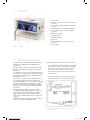
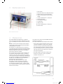
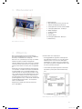
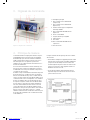
3. Controls
Figure 2: Controls
1 Power switch
2 Bayonet connection for test pressure (positive
pressure)
3 Connection for differential pressure (negative
pressure)
4 Infrared interface for TD600 thermal printer
5 50 mm diameter air connection - negative
pressure
6 OLED colour display
7 Rotating handle
8 Membrane keypad
9 USB port
10 50 mm diameter air connection - positive
pressure
11 Power supply
4. Measuring principle
Leakage testing is stipulated in the European Energy
Performance of Buildings Directive (EPBD) and in
standards like
DIN EN 13779, in order to save energy and to ensure
that air conditioning and ventilation systems operate
efficiently.
The airtightness of duct systems is tested by bringing
the system to a constant test pressure, then measuring
the leakage flow rate that must be supplied in order to
maintain this pressure.
This flow rate corresponds to the leakage rate of the
duct section being tested. The test conditions are
described in DIN EN 12237 for circular ducts and in DIN
EN 1507 for rectangular ducts. DIN EN 1751 contains
the test conditions for dampers and valves, and DIN
EN 15727 covers other air conditioning and ventilation
components.
The leakage tests should be carried out in situ as
described in DIN EN 12599 (usually at lower pressures
as described in the product standards) – "DIN EN
12599 Test procedures and measuring methods for
handing over installed ventilation and air conditioning
systems".
VOB C stipulates that acceptance testing must be car-
ried out in accordance with DIN EN 12599.
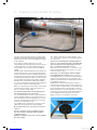
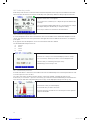
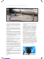
The diagram below illustrates the test setup concept.
• Two integrated fans blow/extract air through the Ø50
mm hose into/out of the connected duct system(s)
being tested. The air supply causes the pressure
in the duct system to increase. This pressure is
returned to the device via the connected pressure
measuring tube.
• In automatic mode, the device automatically brings
the system pressure to the selected test pressure.
Figure 2: Measuring principle, leakage test with the
Lindab LT 600
manual-LTEST-1082_EN-DE-FR-SE.indd 5 2012-03-28 12:32:37

6
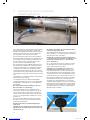
5. Preparing a duct system for testing
The duct system should be tested in accordance with
DIN EN 12237, DIN EN 1507, DIN EN 1507 and DIN EN
12599. A specific pressure may be stipulated as stated
in the standards.
Any positive or negative target pressure can be
selected within the measuring range. If the duct system
is particularly large or complex, leakage testing can
be restricted to sections of the system. (See DIN EN
12599)
DIN EN 12599 compliant leakage testing should be car-
ried out while the duct system is being installed, when
the ducts are still accessible (for example they have not
been insulated yet). The duct surface area being tested
should always be greater than 10 m². The duct surface
area should be measured and calculated as defined in
DIN EN 14239, and should be established in advance.
You are recommended to estimate the anticipated leak-
age flow rate in advance (see the appendix).
Before you start testing, seal off the duct section being
tested from the rest of the system. All openings, out-
lets, etc. must be carefully sealed.
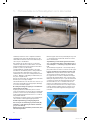
It is extremely important to seal properly around
the openings and the test connections.
The connecting points in the duct system being tested
must be defined in advance, for the 50 mm air hose as
well as the thin pressure measuring tube. The connect-
ing points should be about 2 m apart from each other
to prevent one affecting the other.
Use suitable joints to prepare the connections for the
50mm air hose and the pressure measuring tube.
Do not subject the hose connections to torsional
stresses.
Use the connection on the front (10) for positive
pressure, and the connection on the top (5) for
negative pressure.
Always use adapters on the front, even for negative
pressure testing.
Next, attach the thin pressure measuring tube to the
"+" connection (2) on the front, to the left above the 50
mm connection.
The pressure measuring tube is always attached
to the "+" connection (2). The device automatically
detects positive pressure and negative pressure.
The "-" connection (3) must be left clear.
A bayonet closure is used for the "+" connection of the
pressure measuring tube: turn clockwise to lock and
counterclockwise to open.
In principle, you should always start the leakage
test initially without an adapter. After you find out
the leakage flow rate, you can use the relevant adapter
to improve the measuring accuracy. See page 4. The
adapters have different names, indicating the maximum
measurable flow rate in l/s.
DIN EN 15727 compliant measurements usually use
lower flow rates and are carried out in the same way. It
is also possible to depart from the recommended spac-
ing of 2 m between the hose and the tube. In order to
take measurements on the pressure side for very small
components, the thin 4m tube can be plugged directly
into the adapter instead of the 50 mm hose, and a
nipple connection is used with the component.
Figure 3: Connection to the duct system
manual-LTEST-1082_EN-DE-FR-SE.indd 6 2012-03-28 12:32:38

7
6. Test procedure
If possible, the duct section being tested should be
brought to a positive or negative test pressure equal
to the operating pressure pdesign. The standards state
that the the pressure must be maintained to within ±
5% for five minutes*. The test cycle can be stopped at
any time.
The LT 600 automatically configures the test cycle in
normal operating mode.
In laboratory mode, you can use the arrow keys to
configure the test cycle yourself.
If the selected pressure cannot be reached, the
leakage flow rate can be tested at a lower pres-
sure in accordance with DIN EN 12599 and then
extrapolated for the higher pressure. The device
evaluates the lowest pressures itself.
You should then select a lower test pressure – the
device automatically performs the evaluation on the
basis of the airtightness class.
If the measured leakage flow rate is outside the meas-
uring range of the adapter used, change the adapter
(enter the change of adapter).
It is not necessary to correct the test values to take
account of different temperatures or the air pressure.
Please note the relevant recommendations and com-
ments in DIN EN 1507, DIN EN 12237, DIN EN 1507,
DIN EN 15727 and DIN EN 12599.
* This 5 minute requirement is now virtually obsolete
because modern test equipment is generally much
quicker to bring the test conditions to a stable state.
7. Using for the first time, and performing a test
Use the supplied power cable to connect the Lindab
LT 600 to the mains (230 V, 50 Hz or 110 V, 60 Hz) (11).
Switch on the device with the power switch (1). When
the device powers up, the firmware version appears in
the display. If this is the first time the device has been
used, the display shows the user prompts, otherwise
it shows the operating mode most recently selected in
setup.
7.1 Control panel functions
Note that the display (6) changes according to the
selected status. The display shows the test values and
the options that can be selected from the membrane
keypad (8).
Cursor up
Number input up
Letter input up
Scroll
Print
Back Cursor down Right
Menu Number input down Next
Cursor right Letter input down Select
Confirm
New
Stop
Press the MENU key once to go to the main menu and twice to open the input screen for a test.
manual-LTEST-1082_EN-DE-FR-SE.indd 7 2012-03-28 12:32:38

8
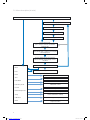
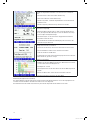
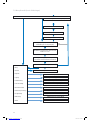
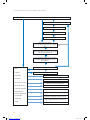
7.2 Menu description (in brief)
Display the bar chart
Permanently save the test
View saved tests
Manual fan control
Custom airtightness class
"Differential pressure measuring instrument"
Device and function settings
Calibration (password protected)
Usage information
Menu
Print
Chart
Save
Data admin
Laboratory mode
Custom
Differential pressure
Setup
Calibration
INFO
Print report
Results
Test in expert mode
(Go to Setup to make this the default
tartup mode)
Enter/change data or start the test using the
values displayed
The test (duration 5 min) runs after the
self test and ends automatically or if it is
cancelled
Select the airtightness class
Enter the test pressure
Enter the surface area being tested
Test in user prompt mode
Start screen
manual-LTEST-1082_EN-DE-FR-SE.indd 8 2012-03-28 12:32:38

9
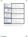
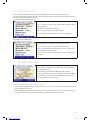
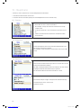
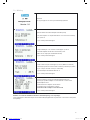
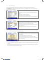
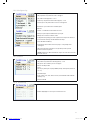
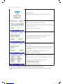
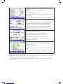
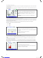
7.3 First test
Display Description
Start screen
Display of device type and firmware version
The device automatically starts in user prompt mode:
• Follow the prompts and select the airtightness class for the test using
the or key.
• Then press the Next key.
• Enter the duct surface area for the test using the or key
Calculated according to DIN EN 14239 or from a CAD system.
(Note: Not the m² calculated according to DIN 18379)
• Then press the Next key.
• Enter the test pressure you want using the or key. (Be careful with
the plus or minus sign)
• Attach the 50 mm air hose depending on the selected pressure (nega-
tive pressure > top of case, positive pressure > front of case).
• Always attach the pressure measuring tube to "+".
• Then press the Next key.
The preliminary calculation of the maximum permitted leakage flow rate
appears here.
The suggested adapter and the current adapter are shown.
• If necessary, change the adapter that is "In use" to the
suggested type using the or key.
Check the installed adapter.
• Then press the Next key.
From here the display is the same in user prompt mode and in expert mode.
Follow the further instructions or adjust the parameters as described in 9. Expert mode.
manual-LTEST-1082_EN-DE-FR-SE.indd 9 2012-03-28 12:32:39

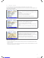
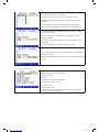
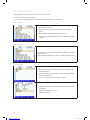
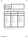
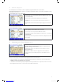
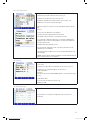
10
Shows the configured parameter and the maximum permitted leakage flow
rate.
• Press the to start the test.
• A self test is carried out before the test starts.
• The test starts once the selected pressure is reached, and continues for
five minutes.
• You can interrupt the test at any time by pressing Stop.
While the test is running, the achieved pressure and the current flow rate
are displayed.
• After the test duration of 300 s, the device stops automatically. (Stand-
ardised test duration) If you press Stop to end the test early, the results
are displayed.
• The device indicates whether the test has passed or failed with the
specified parameters.
• Press the Print key to print the report or press the New key to start a
new test.
Viewing the report before printing.
• You can use the or key to scroll through the report.
• Switch on the TD 600 printer and place it close to the IR window.
• Press OK to start printing.
• Note: The report is not permanently stored unless you select "Save" on
the menu.
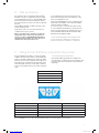
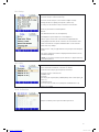
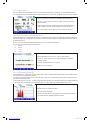
Chart:
• Press the MENU key and press the or key to select Chart from the
menu.
• Confirm by pressing the key.
• You can print the chart by pressing the Print key on the TD 600.
• To return to the menu press the Menu or New key once.
• To start a new test, press the Menu key twice.
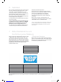
About the chart:
The bar chart shows the permitted leakage flow rate for the airtightness classes, with the specified m² and the actual
test pressure. The test value appears as a red line.
Compliant airtightness classes are shown with green bars. Non-compliant classes are shown with red bars.
manual-LTEST-1082_EN-DE-FR-SE.indd 10 2012-03-28 12:32:39

11
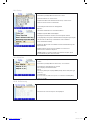
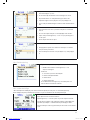
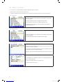
8. Expert mode
If you select expert mode in setup, the device displays the following input screen when it starts up.
You can enter your input or change the displayed parameters directly, as illustrated below using the airtightness class
and the surface area as examples:
Entering/changing the airtightness class:
• Use the or key to select a particular line (the airtightness class in
this example).
• Press the key to change the airtightness class.
• Press the or key to select another line.
• To start the test, select the bottom line and press the key.
Entering/changing the surface area:
• Use the key to select the digit directly for fast input.
• Press the or key to change the selected digit.
• To leave the current input line, press or until you reach the end of
the line.
• Press the or key to select the next input line you want to change.
9. Messages:
If the leakage flow rate calculated in advance exceeds the maximum
output of the device, the following message appears:
"Leakage flow rate too high. Reduce the surface area or the test pressure."
• Change the test conditions by pressing the Back button.
• Press the Next button to skip the message and start the test anyway.
Other messages include:
• "Sensor error" during self test. Switch off the device and restart it. If the error message appears again, the device
needs to be serviced,
• "Overheat" If the device is used for a long time at very high speeds, a safety cutout may be triggered. You can start
using the device again after it has cooled down.
manual-LTEST-1082_EN-DE-FR-SE.indd 11 2012-03-28 12:32:39

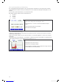
12
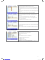
10. Main menu
• Press the or key to move to a different menu entry.
• Press the key to select a menu entry.
• Press the MENU key to open the input screen for a new test.
10.1 Print
• Print the report of the most recent test. Described above on page 11.
• Not available if the device has been switched off in the meantime.
• You can use the or key to scroll through the report.
• Press the Back key to exit the menu or press OK to start printing.
10.2 Chart
• Shows the chart for the most recent test. As described above on page
12.
Not available if device has been switched off in the meantime.
10.3 Save
• Press the key to choose Save from the menu – the customer admin
screen appears.
• On this screen you can create a new customer or save the current test
under existing customers.
• For example, press the key to select the New customer option.
• First create the customer, with any sequence/measuring point name.
• Change lines by pressing the and keys.
• Press the key to select a line.
manual-LTEST-1082_EN-DE-FR-SE.indd 12 2012-03-28 12:32:39

13
• Press the or key to move to the letter/digit you want to change.
Press the and keys to change the letter/digit.
• To exit, press the -or key to move to the end of the line.
• Specify the customer number and sequence name in the same way.
• Select the Create customer line again and press the key.
• Press the Back key to go to the list of customers.
• The new customer appears in the list of customers – select the new
customer by pressing the key.
• The display now shows the available sequences that have been created
for that customer.
• Press the and keys to select the sequence and press the key to
save.
• Saving takes a few seconds.
• The test date is displayed, to confirm that the data have been saved.
• You can create another new sequence in this input screen.
10.4 Data admin
Options for viewing/modifying saved data.
• Change lines by pressing the and keys.
Select a line with the key
Functions:
♦View/print report or chart
♦Select sequences/measuring points
♦Delete customer
♦Delete all customers
The individual functions are dialog-driven so they are not described
in more detail here.
manual-LTEST-1082_EN-DE-FR-SE.indd 13 2012-03-28 12:32:39

14
10.5 Laboratory mode
In laboratory mode, the test is carried out without automatic adjustment of the test pressure and without a time limit.
This mode allows the test to be shortened considerably, and is particularly suitable for taking rough measurements.
• After the self test, this screen appears.
• You can press the and keys to configure the pressure and flow rate
manually.
• You can change the adapter during the test – turn down the fan, change
the adapter and press the ADPT key to change the setting.
• Press Stop to end the test. Continue as described above.
10.6 Custom airtightness class
A custom leakage flow rate U can be selected in the start screen in addition to the standardised airtightness classifi-
cations. This means the tests can be performed in other applications that use different classifications, for example in
power plants.
U only appears when the airtightness classes are selected if the value ≠0 is defined.
The standardised air leakage classes are:
A 27 l/s m²
B 9 l/s m²
C 3 l/s m²
D 1 l/s m²
• Press the or key to move to the letter/digit you want to change.
• You can use the and keys to enter a custom leakage flow rate.
• Save the value you entered by pressing the key.
• Alternatively, press the key to exit.
10.7 Differential pressure
In the idle state after it is switched on, the LT 600 can be used as a differential pressure measuring instrument in order
to monitor a pressure curve over time.
The scale is self-scaling, showing a 120 s block that is continuously updated, overwriting the old test curve.
In this mode, you can use the "-" pressure connection (3) if you want to measure the differential pressure between two
test connections rather than using atmospheric pressure. (E.g. for iris diaphragms, filter pressure drops, etc.)
• Press the PD = 0 key to reset the display.
• Press the Back key to return to the menu.
• Press the Stop key to end the test. You can then press Print to print the
graph on the TD 600.
manual-LTEST-1082_EN-DE-FR-SE.indd 14 2012-03-28 12:32:40

15
10.8 Setup
• Press the and keys to scroll up and down.
• Press the key to select a menu entry.
• Press the and keys to select a letter or digit to change.
• Change the letter or digit by pressing the and keys.
• To exit, press the button until you reach the end of the line.
If necessary, the functions are dialog-driven.
Functions:
• The date/time functions are self-explanatory
• The Brightness option adjusts the screen brightness
• Various options for the units of measurement, explained below
• Setup adjustment allows the PI controller to be customised for auto-
matic measurement, if required. Standard values can be selected.
• Reset to factory settings
• Mode: use the key to toggle between user prompt mode and expert
mode
• The key switches the interface language between German, French,
Swedish and English
• LOGO: you can enter customer-specific text here, to appear at the top
of the report printout
10.9 Units
• Select the units of measurement for the display. The device always
bases its internal calculations on the units l/s and Pa.
• Select the menu entry by pressing the and keys.
• Press the key to select the unit
Available units:
Pressure:
pascal (Pa), hectopascal (hPa), millibar (mBar), water column (mm H2O
and “WC)
Leakage flow rate:
l/s, m³/h, l/min, l/h, CFM, l/s m² (leakage air standardised to 1 m²)
• Exit by pressing OK
10.10 Calibration
• Only accessible by service personnel with a password.
manual-LTEST-1082_EN-DE-FR-SE.indd 15 2012-03-28 12:32:40

16
10.11 Info
• Device information for service.
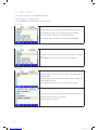
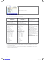
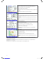
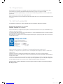
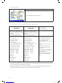
11. Content of report printout
Leakage test
**** Lindab LT600 ****
Version 1.0
Leakage test
**** Lindab LT600 ****
Version 1.0
Notes on the printout
Make and model of device
Firmware version
Test report ID# 148
DIN EN 12237 compliant leakage test
report for duct system
DIN EN 1507 and DIN EN 12599
Test report ID# 149
DIN EN 12237 compliant leakage test
report for duct system
DIN EN 1507 and DIN EN 12599
Consecutive test number
Test object information
Surface area: 121.2 m²
Airtightness class: B
Rate factor
RF: 9 l/s 1/m²
Adapter type: none
Pressure setting: 100 Pa
Test pressure: 99.3 Pa
Leakage flow rate: 11.20 l/s
Test duration: 117 sec
Limit for A: 64.86 l/s
Limit for B: 21.62 l/s
Limit for C: 7.20 l/s
Limit for D: 2.40 l/s
Result:
Test object
Test passed
Date: _20.01.2012
Time: 14:11.
Signature:
Test object information
Surface area: 121.2 m²
Airtightness class: U
Rate factor
RF: 8 l/s 1/m²
Adapter type: none
Pressure setting: --- Pa
Test pressure: 206.6 Pa
Leakage flow rate: 15.65 l/s
Test duration: 0 sec
Limit for A: 104.44 l/s
Limit for B: 34.81 l/s
Limit for C: 11.60 l/s
Limit for D: 3.86 l/s
Result:
Test object
Not passed
Date: _20.01.2012
Time: 14.11.
Signature:
Specified surface area
Selected airtightness class
Leakage flow rate used for analysis
Specified adapter type
Preset pressure (not in laboratory
mode)
Mean pressure actually achieved
Actual leakage flow rate in l/s
Test duration (not in laboratory mode)
Permitted leakage flow rates for
the pressure actually achieved – for
information only
Whether the tested system complies
with the airtightness class
• The printout on the left is an automatic test with airtightness class B, which was stopped after 117 s. (The auto-
matic test duration is 300 s)
• The printout on the right is a test in laboratory mode with a variable (non-standard) airtightness class of 8 l/s m²,
printed after an arbitrary test duration.
manual-LTEST-1082_EN-DE-FR-SE.indd 16 2012-03-28 12:32:40

17
12. Software
Lindab PC software is included as part of the package, and allows a PC to be used for data transmission and admin-
istration.
You can use the software to create customers and measuring points/sequences in advance and upload them to the LT
600.
The software can also be used to install updates of the LT 600 firmware as well as the PC software itself.
A USB cable is included for data transfer.
The software can also be used for other Lindab instruments, and a more detailed description is available separately.
13. Operation and maintenance
There are user serviceable parts inside the LT 600. The device should never be opened by the user.
Only specially trained personnel can open the device.
CAUTION - DANGER TO LIFE! max. 230V 50Hz
The device requires no maintenance apart from the occasional application of light grease on the round sealing ring on
the 50 mm connections. (Silicone grease included)
To change the main fuse, unplug the device from the mains and pull the fuse holder out from the upper edge. The fine-
wire fuses must only be replaced with another fuse of the same type.
The measuring accuracy and operation of the device should be checked regularly (annual checks are suggested) at
the factory or by a suitably equipped testing centre.
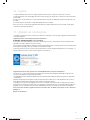
Figure 5: Nameplate and device no.
The device should always have a filter pad fitted in the air intake during operation.
The air intake and outlet must be protected from dirt and moisture. It is essential to prevent dust and water entering
the unit.
Replace the filter pad on a regular basis. A loss of power may indicate dirt at the intake.
The device should only be run from stable electricity networks, not from generators or other supplies that are unable
to deliver continuous power.
The LT 600 has been approved for use as a measuring instrument. It should not ordinarily be used as a way of locating
leakages in duct systems, a process that can sometimes take hours. However, if it is necessary to maintain pressure
for an extended period, you can avoid overloading the fan unnecessarily by not using an adapter.
If the intake is used to try to locate a leakage, no smoke cartridges or mist of any kind may be used.
There is a risk of damaging the device.
manual-LTEST-1082_EN-DE-FR-SE.indd 17 2012-03-28 12:32:41

18
14. Package contents
1 Plastic case containing the following:
1 LT 600
1 Adapter 3.0
1 Adapter 0.3
1 Lindab device software CD
1 USB cable
1 Mains cable 2.5 m 3x1.0
1 DIAMANT type silicone grease, 6 g tube
1 LT 600 filter pads in pack of 5
1 TD 600 high-speed thermal printer
with 1 roll of thermal paper and 4 AA batteries (LR6)
1 Calibration report
1 Operating instructions
1 Aluminium transport case, pilot case type, with carry strap containing the following:
1 Air measuring type 4 m for adapter 0.3 LT 600
2 Brass nipples
1 Hand pump with various adapters
5 Sealing balloons for ventilation systems size 3
5 Sealing balloons for ventilation systems size 5
5 Sealing balloons for ventilation systems size 10
15 Tube clamps for tubes with D 3.2 - 11 mm
1 Air test hose 3.75 m
1 Pressure measuring tube 10 m
1 Pack of thermal paper 57 mm wide, 10 rolls
15. Available accessories and consumables
10 m air test hose, flexible plastic hose, diameter 50 mm, with integrated fit-on cap, diameter 100 mm
1 Pack of thermal paper (10 rolls) for TD 600 thermal printer
Sealing balloon size 3, for diameter 100 to 250 mm
Sealing balloon size 5, for diameter 200 to 400 mm
Sealing balloon size 10, for diameter 315 to 630 mm
LT 600 filter pads in pack of 5
manual-LTEST-1082_EN-DE-FR-SE.indd 18 2012-03-28 12:32:41

19
16. Declaration of conformity
The manufacturer:
Lindab AB
SE-269 82 Båstad, Sweden
Phone +46 (0) 431 850 00
Fax +46 (0) 431 850 10
hereby declares on the basis of third-party testing, that the following product:
Product name: Leakage Tester
Model number: LT 600
conforms with the essential requirements as laid down in the Directive of the Council on the approximation of the laws
of the Member States relating to electromagnetic compatibility, 2004/108/EC, and low voltage, 2006/95/EC.
The following standards were used to evaluate the product with regard to electromagnetic compatibility:
EN 61000 (Electromagnetic Compatibility (EMC))
EN 55011, Class B, EN 55014, EN 55016, EN 55022 (Radio Interference)
Lindab AB Business Area Ventilation 02.03.2012
Torbjörn Bruzelius, Product Manager
manual-LTEST-1082_EN-DE-FR-SE.indd 19 2012-03-28 12:32:42

20
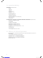
17. Appendix
Theoretical measuring range limits at 230 V 50 Hz
Airtightness class A Airtightness class B Airtightness class C Airtightness class D
20 Pa 290 m² 870 m² 2600 m² 7800 m²
200 Pa 65m² 195 m² 580 m² 1750 m²
2000 Pa 15 m² 44 m² 130 m² 390 m²
You can also download an Excel spreadsheet from www.lindab.ab containing a rough estimate of the anticipated leak-
age flow rate:
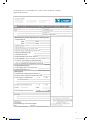
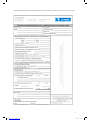
DIN EN 12599 compliant leakage test using the Lindab LT 600 Leakage Tester
Test pressure Surface area
200 Pa 75.00 m²
Airtightness class Max. permitted leakage
flow rate
Adapter
A63.40 l/s No adapter
B21.13 l/s No adapter
C7.0 4 l /s No adapter
D2.35 l/s Adapter 3.0
Example with 200 Pa and 75 m² duct surface area.
manual-LTEST-1082_EN-DE-FR-SE.indd 20 2012-03-28 12:32:42
La page est en cours de chargement...
La page est en cours de chargement...
La page est en cours de chargement...
La page est en cours de chargement...
La page est en cours de chargement...
La page est en cours de chargement...
La page est en cours de chargement...
La page est en cours de chargement...
La page est en cours de chargement...
La page est en cours de chargement...
La page est en cours de chargement...
La page est en cours de chargement...
La page est en cours de chargement...
La page est en cours de chargement...
La page est en cours de chargement...
La page est en cours de chargement...
La page est en cours de chargement...
La page est en cours de chargement...
La page est en cours de chargement...
La page est en cours de chargement...
La page est en cours de chargement...
La page est en cours de chargement...
La page est en cours de chargement...
La page est en cours de chargement...
La page est en cours de chargement...
La page est en cours de chargement...
La page est en cours de chargement...
La page est en cours de chargement...
La page est en cours de chargement...
La page est en cours de chargement...
La page est en cours de chargement...
La page est en cours de chargement...
La page est en cours de chargement...
La page est en cours de chargement...
La page est en cours de chargement...
La page est en cours de chargement...
La page est en cours de chargement...
La page est en cours de chargement...
La page est en cours de chargement...
La page est en cours de chargement...
La page est en cours de chargement...
La page est en cours de chargement...
La page est en cours de chargement...
La page est en cours de chargement...
La page est en cours de chargement...
La page est en cours de chargement...
La page est en cours de chargement...
La page est en cours de chargement...
La page est en cours de chargement...
La page est en cours de chargement...
La page est en cours de chargement...
La page est en cours de chargement...
La page est en cours de chargement...
La page est en cours de chargement...
La page est en cours de chargement...
La page est en cours de chargement...
La page est en cours de chargement...
La page est en cours de chargement...
-
 1
1
-
 2
2
-
 3
3
-
 4
4
-
 5
5
-
 6
6
-
 7
7
-
 8
8
-
 9
9
-
 10
10
-
 11
11
-
 12
12
-
 13
13
-
 14
14
-
 15
15
-
 16
16
-
 17
17
-
 18
18
-
 19
19
-
 20
20
-
 21
21
-
 22
22
-
 23
23
-
 24
24
-
 25
25
-
 26
26
-
 27
27
-
 28
28
-
 29
29
-
 30
30
-
 31
31
-
 32
32
-
 33
33
-
 34
34
-
 35
35
-
 36
36
-
 37
37
-
 38
38
-
 39
39
-
 40
40
-
 41
41
-
 42
42
-
 43
43
-
 44
44
-
 45
45
-
 46
46
-
 47
47
-
 48
48
-
 49
49
-
 50
50
-
 51
51
-
 52
52
-
 53
53
-
 54
54
-
 55
55
-
 56
56
-
 57
57
-
 58
58
-
 59
59
-
 60
60
-
 61
61
-
 62
62
-
 63
63
-
 64
64
-
 65
65
-
 66
66
-
 67
67
-
 68
68
-
 69
69
-
 70
70
-
 71
71
-
 72
72
-
 73
73
-
 74
74
-
 75
75
-
 76
76
-
 77
77
-
 78
78


Lindab LTEST Operating Instructions Manual
- Catégorie
- Mesure
- Taper
- Operating Instructions Manual
dans d''autres langues
- Deutsch: Lindab LTEST
- svenska: Lindab LTEST
Documents connexes
Autres documents
-
 METREL OmegaPATPlus MI 3305 Manuel utilisateur
-
Trox X-CUBE X2 Mode d'emploi
-
-
Aiwa AV-X120 Manuel utilisateur
-
 Hach ORBISPHERE 3650 Atex Manuel utilisateur
-
Appro Dionex UltiMate 3000 Series Mode d'emploi
-
Casella APEX Personal Sampling Pump Manuel utilisateur
-
Friedrich MD12Y3JM Mode d'emploi
-
YOKOGAWA MT300 Getting Started Manual
-
Cuckoo CRP-P1009S Le manuel du propriétaire

