www.mellanox.com
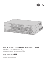
SwitchX® 64 Port SFP+ Ethernet Switch
Hardware User Manual
P/N: MSX1016X-2BFR, MSX1016X-2BRR
Rev 1.2

Document Number: 3727
Rev 1.2
Mellanox Technologies
2
Mellanox Technologies
350 Oakmead Parkway Suite 100
Sunnyvale, CA 94085
U.S.A.
www.mellanox.com
Tel: (408) 970-3400
Fax: (408) 970-3403
Mellanox Technologies, Ltd.
Beit Mellanox
PO Box 586 Yokneam 20692
Israel
www.mellanox.com
Tel: +972 (0)74 723 7200
Fax: +972 (0)4 959 3245
Mellanox®, Mellanox logo, BridgeX®, ConnectX®, CORE-Direct®, InfiniBridge®, InfiniHost®, InfiniScale®, PhyX®,
SwitchX®, Virtual Protocol Interconnect® and Voltaire® are registered trademarks of Mellanox Technologies, Ltd.
Connect-IB™, FabricIT™, MLNX-OS™, ScalableHPC™, Unbreakable-Link™, UFM™ and Unified Fabric Manager™ are
trademarks of Mellanox Technologies, Ltd. All other trademarks are property of their respective owners.
© Copyright 2012. Mellanox Technologies. All Rights Reserved.
NOTE:
THIS HARDWARE, SOFTWARE OR TEST SUITE PRODUCT (“PRODUCT(S)”) AND ITS RELATED
DOCUMENTATION ARE PROVIDED BY MELLANOX TECHNOLOGIES “AS-IS” WITH ALL FAULTS OF ANY
KIND AND SOLELY FOR THE PURPOSE OF AIDING THE CUSTOMER IN TESTING APPLICATIONS THAT USE
THE PRODUCTS IN DESIGNATED SOLUTIONS. THE CUSTOMER'S MANUFACTURING TEST ENVIRONMENT
HAS NOT MET THE STANDARDS SET BY MELLANOX TECHNOLOGIES TO FULLY QUALIFY THE
PRODUCTO(S) AND/OR THE SYSTEM USING IT. THEREFORE, MELLANOX TECHNOLOGIES CANNOT AND
DOES NOT GUARANTEE OR WARRANT THAT THE PRODUCTS WILL OPERATE WITH THE HIGHEST
QUALITY. ANY EXPRESS OR IMPLIED WARRANTIES, INCLUDING, BUT NOT LIMITED TO, THE IMPLIED
WARRANTIES OF MERCHANTABILITY, FITNESS FOR A PARTICULAR PURPOSE AND NONINFRINGEMENT
ARE DISCLAIMED. IN NO EVENT SHALL MELLANOX BE LIABLE TO CUSTOMER OR ANY THIRD PARTIES
FOR ANY DIRECT, INDIRECT, SPECIAL, EXEMPLARY, OR CONSEQUENTIAL DAMAGES OF ANY KIND
(INCLUDING, BUT NOT LIMITED TO, PAYMENT FOR PROCUREMENT OF SUBSTITUTE GOODS OR SERVICES;
LOSS OF USE, DATA, OR PROFITS; OR BUSINESS INTERRUPTION) HOWEVER CAUSED AND ON ANY
THEORY OF LIABILITY, WHETHER IN CONTRACT, STRICT LIABILITY, OR TORT (INCLUDING NEGLIGENCE
OR OTHERWISE) ARISING IN ANY WAY FROM THE USE OF THE PRODUCT(S) AND RELATED
DOCUMENTATION EVEN IF ADVISED OF THE POSSIBILITY OF SUCH DAMAGE.

SwitchX® 64 Port SFP+ Ethernet Switch Hardware User Manual Rev 1.2
Mellanox Technologies
3
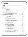
Contents
Contents. . . . . . . . . . . . . . . . . . . . . . . . . . . . . . . . . . . . . . . . . . . . . . . . . . . . . . . . . . 3
List of Figures . . . . . . . . . . . . . . . . . . . . . . . . . . . . . . . . . . . . . . . . . . . . . . . . . . . . . 5
List of Tables. . . . . . . . . . . . . . . . . . . . . . . . . . . . . . . . . . . . . . . . . . . . . . . . . . . . . . 6
Revision History . . . . . . . . . . . . . . . . . . . . . . . . . . . . . . . . . . . . . . . . . . . . . . . . . . . 7
About this Manual. . . . . . . . . . . . . . . . . . . . . . . . . . . . . . . . . . . . . . . . . . . . . . . . . . 8
Intended Audience . . . . . . . . . . . . . . . . . . . . . . . . . . . . . . . . . . . . . . . . . . . .8
Related Documentation . . . . . . . . . . . . . . . . . . . . . . . . . . . . . . . . . . . . . . . .8
Conventions . . . . . . . . . . . . . . . . . . . . . . . . . . . . . . . . . . . . . . . . . . . . . . . . .8
Mellanox Part Numbering Legend . . . . . . . . . . . . . . . . . . . . . . . . . . . . . . . .9
Chapter 1 Overview . . . . . . . . . . . . . . . . . . . . . . . . . . . . . . . . . . . . . . . . . . . . . . . 10
1.1 Features . . . . . . . . . . . . . . . . . . . . . . . . . . . . . . . . . . . . . . . . . . . . . . . . . .10
1.2 Serial Number and Product Version Information . . . . . . . . . . . . . . . . . . .11
Chapter 2 Installation Safety Warnings . . . . . . . . . . . . . . . . . . . . . . . . . . . . . . . 12
Chapter 3 Hardware Basic Operation and Installation. . . . . . . . . . . . . . . . . . . 15
3.1 Switch Platform Hardware Overview . . . . . . . . . . . . . . . . . . . . . . . . . . . .15
3.1.1 LED Assignments. . . . . . . . . . . . . . . . . . . . . . . . . . . . . . . . . . . . . . . . . . . 15
3.1.2 Port Connector LED Assignment . . . . . . . . . . . . . . . . . . . . . . . . . . . . . . . 18
3.2 Air Flow . . . . . . . . . . . . . . . . . . . . . . . . . . . . . . . . . . . . . . . . . . . . . . . . . . .18
3.3 SFP+ Cable Power Budget Classification . . . . . . . . . . . . . . . . . . . . . . . .18
3.4 Interfaces . . . . . . . . . . . . . . . . . . . . . . . . . . . . . . . . . . . . . . . . . . . . . . . . .19
3.4.1 Port Connector Interfaces. . . . . . . . . . . . . . . . . . . . . . . . . . . . . . . . . . . . . 19
3.5 Management and Firmware Updating Interfaces . . . . . . . . . . . . . . . . . . .19
3.5.1 RJ-45 Console Connector . . . . . . . . . . . . . . . . . . . . . . . . . . . . . . . . . . . . 19
3.5.2 Mini USB. . . . . . . . . . . . . . . . . . . . . . . . . . . . . . . . . . . . . . . . . . . . . . . . . . 19
3.5.3 RJ-45 Ethernet Connector . . . . . . . . . . . . . . . . . . . . . . . . . . . . . . . . . . . . 19
3.5.4 I2C Connector . . . . . . . . . . . . . . . . . . . . . . . . . . . . . . . . . . . . . . . . . . . . . 20
Chapter 4 Installation . . . . . . . . . . . . . . . . . . . . . . . . . . . . . . . . . . . . . . . . . . . . . 21
4.1 Package Contents and Installation . . . . . . . . . . . . . . . . . . . . . . . . . . . . . .21
4.1.1 Installing the Switch in the Rack. . . . . . . . . . . . . . . . . . . . . . . . . . . . . . . . 21
4.1.2 Power Connections and Initial Power On. . . . . . . . . . . . . . . . . . . . . . . . . 26
4.1.3 Grounding the Switch . . . . . . . . . . . . . . . . . . . . . . . . . . . . . . . . . . . . . . . . 27
4.1.4 Cable Installation . . . . . . . . . . . . . . . . . . . . . . . . . . . . . . . . . . . . . . . . . . . 27
4.1.5 Cable Orientation . . . . . . . . . . . . . . . . . . . . . . . . . . . . . . . . . . . . . . . . . . . 28
4.1.6 Supported Approved Cables . . . . . . . . . . . . . . . . . . . . . . . . . . . . . . . . . . 28
4.2 Disposal . . . . . . . . . . . . . . . . . . . . . . . . . . . . . . . . . . . . . . . . . . . . . . . . . .28
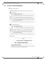
Chapter 5 Management and Tools Overview . . . . . . . . . . . . . . . . . . . . . . . . . . 29
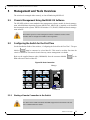
5.1 Chassis Management Using the MLNX-OS Software . . . . . . . . . . . . . . .29
5.2 Configuring the Switch for the First Time . . . . . . . . . . . . . . . . . . . . . . . .29
5.2.1 Starting a Remote Connection to the Switch . . . . . . . . . . . . . . . . . . . . . . 29
5.2.2 Upgrading Software . . . . . . . . . . . . . . . . . . . . . . . . . . . . . . . . . . . . . . . . . 30

Rev 1.2
Mellanox Technologies
4
Chapter 6 Troubleshooting. . . . . . . . . . . . . . . . . . . . . . . . . . . . . . . . . . . . . . . . . 31
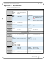
Appendix A Specification . . . . . . . . . . . . . . . . . . . . . . . . . . . . . . . . . . . . . . . . . . 33
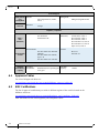
A.1 Approved Cables . . . . . . . . . . . . . . . . . . . . . . . . . . . . . . . . . . . . . . . . .35
A.2 EMC Certifications . . . . . . . . . . . . . . . . . . . . . . . . . . . . . . . . . . . . . . . .35
A.3 China CCC Warning Statement . . . . . . . . . . . . . . . . . . . . . . . . . . . . . .36
Appendix B Thermal Threshold Definitions . . . . . . . . . . . . . . . . . . . . . . . . . . . 37
Appendix C Transferring the Power Cord . . . . . . . . . . . . . . . . . . . . . . . . . . . . . 38
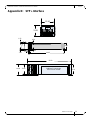
Appendix D SFP+ Interface . . . . . . . . . . . . . . . . . . . . . . . . . . . . . . . . . . . . . . . . . 40
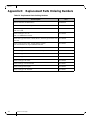
Appendix E Replacement Parts Ordering Numbers . . . . . . . . . . . . . . . . . . . . . 43
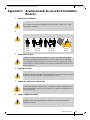
Appendix F Avertissements de sécurité d’installation (French) . . . . . . . . . . . 44
Appendix G Installation - Sicherheitshinweise (German) . . . . . . . . . . . . . . . . 47
Appendix H Advertencias de seguridad para la instalación (Spanish). . . . . . 51
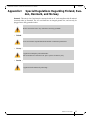
Appendix I Special Regulations Regarding Finland, Sweden, Denmark, and Norway 54

SwitchX® 64 Port SFP+ Ethernet Switch Hardware User Manual Rev 1.2
Mellanox Technologies
5
List of Figures
Figure 1: SX1016 Switch . . . . . . . . . . . . . . . . . . . . . . . . . . . . . . . . . . . . . . . . . . . . . . . . . .10
Figure 2: Generic Product label. . . . . . . . . . . . . . . . . . . . . . . . . . . . . . . . . . . . . . . . . . . . . .11
Figure 3: Management MAC Label . . . . . . . . . . . . . . . . . . . . . . . . . . . . . . . . . . . . . . . . . .11
Figure 4: Switch System Front Panel . . . . . . . . . . . . . . . . . . . . . . . . . . . . . . . . . . . . . . . . .15
Figure 5: Status LEDs. . . . . . . . . . . . . . . . . . . . . . . . . . . . . . . . . . . . . . . . . . . . . . . . . . . . .15
Figure 6: LED to Port Assignment. . . . . . . . . . . . . . . . . . . . . . . . . . . . . . . . . . . . . . . . . . . .18
Figure 7: Port Numbering . . . . . . . . . . . . . . . . . . . . . . . . . . . . . . . . . . . . . . . . . . . . . . . . . .19
Figure 8: Management Interfaces . . . . . . . . . . . . . . . . . . . . . . . . . . . . . . . . . . . . . . . . . . . .19
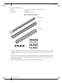
Figure 9: Rack Rail Kit Parts . . . . . . . . . . . . . . . . . . . . . . . . . . . . . . . . . . . . . . . . . . . . . . .22
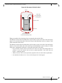
Figure 10: Placement of Switch in Rack . . . . . . . . . . . . . . . . . . . . . . . . . . . . . . . . . . . . . . . .23
Figure 11: Mounting Options . . . . . . . . . . . . . . . . . . . . . . . . . . . . . . . . . . . . . . . . . . . . . . . .24
Figure 12: Screwing on the Rail . . . . . . . . . . . . . . . . . . . . . . . . . . . . . . . . . . . . . . . . . . . . . .25
Figure 13: Inserting the Caged Nuts . . . . . . . . . . . . . . . . . . . . . . . . . . . . . . . . . . . . . . . . . . .25
Figure 14: Slide the Rail into the Rail Slide. . . . . . . . . . . . . . . . . . . . . . . . . . . . . . . . . . . . . .26
Figure 15: Cable Orientation for Insertion. . . . . . . . . . . . . . . . . . . . . . . . . . . . . . . . . . . . . . .28
Figure 16: Host Connection . . . . . . . . . . . . . . . . . . . . . . . . . . . . . . . . . . . . . . . . . . . . . . . . .29
Figure 17: Transfer Power Cord . . . . . . . . . . . . . . . . . . . . . . . . . . . . . . . . . . . . . . . . . . . . .38
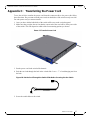
Figure 18: Put the Cord Through the Switch Slide Before Screwing it to the Switch . . . . . .38
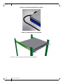
Figure 19: Screw the Switch Slide to the Switch. . . . . . . . . . . . . . . . . . . . . . . . . . . . . . . . . .39
Figure 20: Transfer Power Cord Finished . . . . . . . . . . . . . . . . . . . . . . . . . . . . . . . . . . . . . .39

Rev 1.2
Mellanox Technologies
6
List of Tables
Table 1: Revision History Table. . . . . . . . . . . . . . . . . . . . . . . . . . . . . . . . . . . . . . . . . . . . . 7
Table 2: Reference Documents . . . . . . . . . . . . . . . . . . . . . . . . . . . . . . . . . . . . . . . . . . . . . 8
Table 3: Switch Status LED Configurations . . . . . . . . . . . . . . . . . . . . . . . . . . . . . . . . . . 16
Table 4: Fan LED Configurations . . . . . . . . . . . . . . . . . . . . . . . . . . . . . . . . . . . . . . . . . . 16
Table 5: Bad Port LED Configurations . . . . . . . . . . . . . . . . . . . . . . . . . . . . . . . . . . . . . . 17
Table 6: Port Connector Physical and Logical Link Indications . . . . . . . . . . . . . . . . . . . 18
Table 7: Installation Kit According to Rack Size. . . . . . . . . . . . . . . . . . . . . . . . . . . . . . . . 21
Table 8: SX1016 Specification Data . . . . . . . . . . . . . . . . . . . . . . . . . . . . . . . . . . . . . . . . 33
Table 9: SFP+ Pinout. . . . . . . . . . . . . . . . . . . . . . . . . . . . . . . . . . . . . . . . . . . . . . . . . . . . 41
Table 10: Replacement Parts Ordering Numbers . . . . . . . . . . . . . . . . . . . . . . . . . . . . . . . 43

SwitchX® 64 Port SFP+ Ethernet Switch Hardware User Manual Rev 1.2
Mellanox Technologies
7
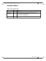
Revision History
Table 1 - Revision History Table
Date Revision Description
November 2012 Rev 1.2 Removed Updating FW section; not needed for Ethernet switches
October 2012 Rev 1.1 • Added China CCC Warning Statement
• Fixes to port to LED assignment
February 2012 Rev 1.0 Initial release

Rev 1.2
Mellanox Technologies
8
About this Manual
This manual describes the installation and basic use of the Mellanox SX1016 switch, which is
based on the SwitchX® switch device.
Intended Audience
This manual is intended for users and system administrators responsible for installing and setting
up the switch platforms listed above.
The manual assumes familiarity with Ethernet Networks and Architecture.
Related Documentation
Additional Documentation available from Mellanox:
Conventions
Throughout this manual, the name SX1016 and the term switch are used to describe the 64-port
SFP+ 10Gb/s switch unless explicitly indicated otherwise.
The following icons are used throughout this document to indicate information that is important
to the user.
Table 2 - Reference Documents
Switch Firmware and
Firmware Update
Tools
See
http://www.mellanox.com > Support > Download Firmware Tools
This symbol signals recommendations to the user.
This symbol indicates information that is helpful to the user.
This symbol indicates a situation that can potentially cause damage to hardware or
software.
BEWARE! This symbol indicates a situation that can potentially cause personal injury
or damage to hardware or software.

SwitchX® 64 Port SFP+ Ethernet Switch Hardware User Manual Rev 1.2
Mellanox Technologies
9
Mellanox Part Numbering Legend
Place Field Decoder
M Mellanox Technologies
SX System Type SwitchX® silicon
B Protocol (1, 2, 3, 4) = Ethernet
C Height of Unit 0 = 1U
1 = 1.5U
2 = 2U
FF # of 40Gb/s Ports equivalent 16
G Line rate of the fastest port X = 10GbE
- Separator
# Power supplies
number of power supplies
shipped with the basic sys-
tem
2 = 2 power supplies
M Depth of the Unit B = short depth
Y Air Flow direction R= Connector side to PSU side airflow
F= PSU side to connector side airflow
R Chip Generation R – SwitchX
S – SwitchX-2

Overview
Rev 1.2
Mellanox Technologies
10
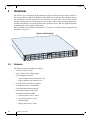
1 Overview
The SX1016 is an economical, high-performance 64-port 10GbE switch providing 1.28Tb/s of
line rate performance. Based on Mellanox’s SwitchX® silicon and innovative hardware design,
the switch packs 64 SFP+ interfaces in an ultra-dense 1U form factor. The SX1016 features
industry leading latency of 250ns and power of less than 1.0W per port, providing optimal per-
formance and efficiency for enterprise data center, financial services, Web 2.0, High Performance
Computing and cloud computing applications.
Basic installation and hardware maintenance is covered in “Hardware Basic Operation and
Installation” on page 15.
Figure 1: SX1016 Switch
1.1 Features
The SX1016 supports the following features:
• 64 SFP+ ports of 10 Gb/s
• up to 24 native Fiber Channel ports
• Two management options:
• Supports Mellanox PPC460 Mezzanine CPU
• Supports Mellanox X86 Mezzanine CPU
• 2 250W AC/DC fixed Power supplies
• 6 Fixed Fans with 5+1 redundancy
• On board temperature monitoring
• Reset Push button on front panel
• Front Panel indication LEDs:
• Status LED (Red / Yellow / Green)
• Fans Status LED (Red / Green)
• UID LED (Blue)
• Bad port LED (Yellow / Green)
RST
UID
S
X
1
0
1
6

SwitchX® 64 Port SFP+ Ethernet Switch Hardware User Manual Rev 1.2
Mellanox Technologies
11
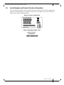
1.2 Serial Number and Product Version Information
The serial number and MAC for the switch are found on the back panel. The serial number and
product version information are found on the label seen in the figure below. Near this label is
another label with the management MAC.
Figure 2: Generic Product label
Figure 3: Management MAC Label
P/N:MSX1016X‐2BFR
Rev:X1
MadeinIsrael
MAC:0002C902004C
S/N:MT0924X00266
ManagementMAC:
0002C902004C

Installation Safety Warnings
Rev 1.2
Mellanox Technologies
12
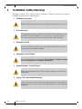
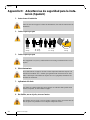
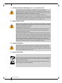
2 Installation Safety Warnings
Warnings in French can be found on page 43. Warnings in German can be found on page 46.
Warnings in Spanish can be found on page 50.
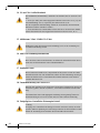
1. Installation Instructions
2. Over-temperature
3. Stacking the Chassis
4. Double pole / Neutral Fusing
5. During Lightning - Electrical Hazard
6. Copper Cable Connecting/Disconnecting
Read all installation instructions before connecting the equipment to the power source.
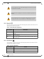
This equipment should not be operated in an area with an ambient temperature exceed-
ing the maximum recommended: 45°C (113°F). Moreover, to guarantee proper air
flow, allow at least 8cm (3 inches) of clearance around the ventilation openings.
The chassis should not be stacked on any other equipment. If the chassis falls, it can
cause bodily injury and equipment damage.
This system has double pole/neutral fusing. Remove all power cords before opening
the cover of this product or touching any internal parts.
During periods of lightning activity, do not work on the equipment or connect or dis-
connect cables.
Copper cables are heavy and not flexible, as such they should be carefully attached to
or detached from the connectors. Refer to the cable manufacturer for special warnings/
instructions.

SwitchX® 64 Port SFP+ Ethernet Switch Hardware User Manual Rev 1.2
Mellanox Technologies
13
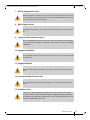
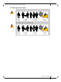
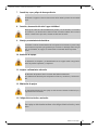
7. Rack Mounting and Servicing
8. High Leakage Current
9. Connect a Valid Ground to this Device
10. Equipment Installation
11. Equipment Disposal
12. Local and National Electrical Codes
13. Installation Codes
When this product is mounted or serviced in a rack, special precautions must be taken
to ensure that the system remains stable. In general you should fill the rack with equip-
ment starting from the bottom to the top.
WARNING: High leakage current; Earth connection essential before connecting sup-
ply.
Before connecting this device to the power line, the protective earth terminal
screws of this device must be connected to the protective earth in the building
installation.
This equipment should be installed, replaced, and/or serviced only by trained and qual-
ified personnel.
Disposal of this equipment should be in accordance to all national laws and regula-
tions.
This equipment should be installed in compliance with local and national electrical
codes.
This device must be installed according to the latest version of the country
national electrical codes. For North America, equipment must be installed in
accordance to the applicable requirements in the US National Electrical Code
and the Canadian Electrical Code.

Installation Safety Warnings
Rev 1.2
Mellanox Technologies
14
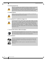
14. Interconnection Of Units
15. Suitable Enclosure
16. UL Listed and CSA Certified Power Supply Cord
17. Do Not Use the Switch as a Shelf or Work Space.
18. WEEE Directive
Cables for connecting to the unit RS232 and Ethernet Interfaces must be UL
certified type DP-1 or DP-2. (Note- when residing in non LPS circuit)
Overcurrent Protection: A readily accessible Listed branch circuit overcurrent
protective device rated 20 A must be incorporated in the building wiring.
Suitable electrical, mechanical and fire enclosure shall be provided by the
end product manufacturer and or the end user.
For North American power connection, select a power supply cord that is UL Listed
and CSA Certified, 3 - conductor, [16 AWG], terminated with a molded plug rated at
125 V, [13 A], with a minimum length of 1.5m [six feet] but no longer than 4.5m.
For European connection, select a power supply cord that is internationally
harmonized and marked “<HAR>”, 3 - conductor, minimum 1.0 mm 2 wire,
rated at 300 V, with a PVC insulated jacket. The cord must have a molded plug
rated at 250 V, 10 A.
Caution: Slide/rail mounted equipment is not to be used as a shelf or a work space. The
rails are not intended for sliding the unit away from the rack. It is for permanent instal-
lation at final resting place only, not used for service and maintenance.
According to the WEEE Directive 2002/96/EC, all waste electrical and electronic
equipment (EEE) should be collected separately and not disposed of with regular
household waste.
Dispose of this product and all of its parts in a responsible and environmentally
friendly way.

SwitchX® 64 Port SFP+ Ethernet Switch Hardware User Manual Rev 1.2
Mellanox Technologies
15
3 Hardware Basic Operation and Installation
3.1 Switch Platform Hardware Overview
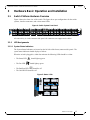
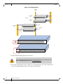
Figure 4 shows the front view of the switch. The figure shows port configurations for the switch
systems, interface connectors, and various status LEDs.
Figure 4: Switch System Front Panel
All connectivity is via the connector side panel. All connectors can support active cables.
3.1.1 LED Assignments
3.1.1.1 System Status Indicators
The System Status Indicators are located on the left side of the front (connector side) panel. The
system status indicators should display as follows:
When the switch is plugged in, within four minutes the following LEDs should be evident.
•The Status LED should light up green.
• The Fan LED should light up green.
• The Bad Port LED should be off.
• The Unit ID LED should be off.
Figure 5: Status LEDs
SX1016
UID
Mellanox
RST
UID
RST

Hardware Basic Operation and Installation
Rev 1.2
Mellanox Technologies
16
3.1.1.2 Status LED
The status indicator is located on the left side of the front panel (connector side) of the unit. The
following status conditions are possible:
Table 3 - Switch Status LED Configurations
3.1.1.3 Fan Indicators
The fan indicator is located on the left side of the front panel (connector side) of the unit. The fol-
lowing fan status conditions are possible:
Table 4 - Fan LED Configurations
If the status LED shows red after four minutes unplug the switch and call your Mella-
nox representative for assistance.
If the fan LED shows red unplug the switch and call your Mellanox representative for
assistance.
If the switch shuts down due to over-temperature, unplug the switch, wait 5 minutes
and replug in the switch. For more information See “Troubleshooting” on page 31.
LED Configuration LED Description
Off No power to the switch.
Solid Green OK – the switch is running.
All OK.
Blinking Green Switch is booting up.
Red Error – there is a problem with power output from the power supply, or there is a
thermal shut down.
LED Configuration FAN LED
Off There is no power to the fans.
Green OK – the fans are running.
Red Error – the fans are not operating properly. Replace the switch.

SwitchX® 64 Port SFP+ Ethernet Switch Hardware User Manual Rev 1.2
Mellanox Technologies
17
3.1.1.4 Bad Port LED
The bad port indicator is located on the left side of the front panel (connector side) of the unit.
The following bad port conditions are possible:
Table 5 - Bad Port LED Configurations
This LED shows symbol errors. Possible causes for this are:
•bad cable
• bad connection
• bad connector
This LED lights up when one or more ports is receiving a symbol error. The LED immediately
goes off until the next symbol error is received.
3.1.1.5 UID LED Switch Identifier
The UID LED is a debug feature that will become available to customers in the near future. For
details please contact Mellanox Technologies support.
3.1.1.6 Port Connector LED
The port LEDs are assigned to the ports as in figure:
Fans must be operating while the power supply is plugged in.
If the switch shuts down due to over-temperature, unplug the switch, wait 5 minutes
and replug in the switch. For more information See “Troubleshooting” on page 31.
LED Configuration Description
Off OK – all ports are up and running.
Flashing Orange Error – one or possibly more ports has just received a symbol error.

Hardware Basic Operation and Installation
Rev 1.2
Mellanox Technologies
18
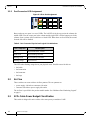
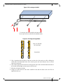
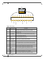
3.1.2 Port Connector LED Assignment
Figure 6: LED to Port Assignment
Between the top two ports is a row of LEDs. The left LED is for the top port in the column, the
middle LED is for the center port in the column and the right LED is for the bottom port in the
column. Some versions of this switch have a fourth LED. When there are four LEDs, the second
from the left will be disabled.
Table 6 - Port Connector Physical and Logical Link Indications
This LED when flashing orange shows port physical errors. Possible causes for this are:
•bad cable
• bad connection
• bad connector
•bad cage
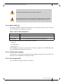
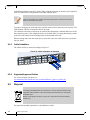
3.2 Air Flow
These switches can come with two air flow patterns. The two patterns are:
• power supply side inlet to connector side outlet
• connector side inlet to power supply side outlet
The air flow is specified in the product model number. See “Mellanox Part Numbering Legend”
on page 9.
3.3 SFP+ Cable Power Budget Classification
This switch is designed for active cables with a max power per module of 1.0W.
LED Configuration LED Description
Off Physical link down / Default
Solid Green Physical link up no traffic
Flashing Green Physical link up with traffic
Flashing Orange Physical errors
RST
UID

SwitchX® 64 Port SFP+ Ethernet Switch Hardware User Manual Rev 1.2
Mellanox Technologies
19
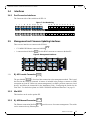
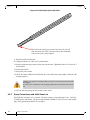
3.4 Interfaces
3.4.1 Port Connector Interfaces
The Connector side of the switch has 64 SFP+ 10
Figure 7: Port Numbering
3.5 Management and Firmware Updating Interfaces
There are two interfaces to connect to the SX1016:
• 1 X 100M/1Gb Ethernet connectors labelled
• 1 connector that is labelled Use this RJ-45 connector to connect to the host PC
Figure 8: Management Interfaces
3.5.1 RJ-45 Console Connector
The port labelled is for a local host connection to the management module. This is used
the first time the switch is connected. A harness is included in the package to connect to a DB9
connection on a host PC. Before any remote management is available you must connect to a local
host PC and follow the instructions in the Installation Guide, “Configuring the Switch for the
First Time”. For the Socket pinout see “RJ45 CONSOLE and Ethernet Interfaces” on page 51.
3.5.2 Mini USB
This interface can be used to update SW.
3.5.3 RJ-45 Ethernet Connector
The Ethernet connection labelled provides access for remote management. The switch
can be connected to any Ethernet port.
1
2
3
4
5
6
7
8
9
10
11
12
13
14
15
16
17
18
19
20
21
22
23
24
25
26
27
28
29
30
31
32
33
34
35
36
37
38
39
40
41
42
43
44
45
46
47
48
49
50
51
52
53
54
55
56
57
58
59
60
61
62
63
64
SX1016
Mellanox

Hardware Basic Operation and Installation
Rev 1.2
Mellanox Technologies
20
3.5.4 I2C Connector
There is an “I2C”interface on the side panel. This interface is only for FAEs and advanced users.
Warning: Any red status LED is cause for concern and must be dealt with immediately.
It can take up to 4 minutes to boot up, during which time the status LED may indicate
red.
La page est en cours de chargement...
La page est en cours de chargement...
La page est en cours de chargement...
La page est en cours de chargement...
La page est en cours de chargement...
La page est en cours de chargement...
La page est en cours de chargement...
La page est en cours de chargement...
La page est en cours de chargement...
La page est en cours de chargement...
La page est en cours de chargement...
La page est en cours de chargement...
La page est en cours de chargement...
La page est en cours de chargement...
La page est en cours de chargement...
La page est en cours de chargement...
La page est en cours de chargement...
La page est en cours de chargement...
La page est en cours de chargement...
La page est en cours de chargement...
La page est en cours de chargement...
La page est en cours de chargement...
La page est en cours de chargement...
La page est en cours de chargement...
La page est en cours de chargement...
La page est en cours de chargement...
La page est en cours de chargement...
La page est en cours de chargement...
La page est en cours de chargement...
La page est en cours de chargement...
La page est en cours de chargement...
La page est en cours de chargement...
La page est en cours de chargement...
-
 1
1
-
 2
2
-
 3
3
-
 4
4
-
 5
5
-
 6
6
-
 7
7
-
 8
8
-
 9
9
-
 10
10
-
 11
11
-
 12
12
-
 13
13
-
 14
14
-
 15
15
-
 16
16
-
 17
17
-
 18
18
-
 19
19
-
 20
20
-
 21
21
-
 22
22
-
 23
23
-
 24
24
-
 25
25
-
 26
26
-
 27
27
-
 28
28
-
 29
29
-
 30
30
-
 31
31
-
 32
32
-
 33
33
-
 34
34
-
 35
35
-
 36
36
-
 37
37
-
 38
38
-
 39
39
-
 40
40
-
 41
41
-
 42
42
-
 43
43
-
 44
44
-
 45
45
-
 46
46
-
 47
47
-
 48
48
-
 49
49
-
 50
50
-
 51
51
-
 52
52
-
 53
53


Mellanox Technologies SwitchX MSX1016X-2BFR Hardware User Manual
- Taper
- Hardware User Manual
- Ce manuel convient également à
dans d''autres langues
Documents connexes
-
Mellanox Technologies MSX1024B-1BRS Manuel utilisateur
-
Mellanox Technologies MSX1012B-2BFS Manuel utilisateur
-
Mellanox Technologies MIS5024Q-1BRR Manuel utilisateur
-
-
-
-
Mellanox Technologies MCX453A-FCAT Manuel utilisateur
-
-
Mellanox Technologies MSX6036G-2SFS Manuel utilisateur
-