Generac SB15130GENG Le manuel du propriétaire
- Catégorie
- Souffleuses à neige
- Taper
- Le manuel du propriétaire
Ce manuel convient également à

Owner’s Manual
GC2800B and GC3000B Snow Blower
SAVE THIS MANUAL FOR FUTURE REFERENCE
Register your Generac product at:
WWW.GENERAC.COM
1-888-GENERAC
(888-436-3722)
MODEL NUMBER: _________________________
SERIAL NUMBER: _________________________
DATE PURCHASED:________________________
Original Instructions

ii Owner’s Manual for Snow Blower
(000393a)
WARNING
CANCER AND REPRODUCTIVE HARM
www.P65Warnings.ca.gov.

Owner’s Manual for Snow Blower iii
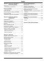
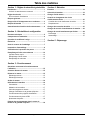
Table of Contents
Section 1: Safety Rules & General
Information
Introduction ..................................................................1
Read This Manual Thoroughly ....................................1
Safety Rules .................................................................1
How to Obtain Service .................................................1
General Hazards ...........................................................2
Exhaust and Fuel Hazards ..........................................3
Fire Hazards .................................................................3
Safety and Operating Decals ......................................4
Section 2: General Information and Setup
Specifications ...............................................................5
Components and Controls ..........................................6
Know Your Snowblower ..............................................7
Emissions .....................................................................7
Remove Contents from Carton ...................................7
Assembly Instructions ................................................8
Checking Tire Pressure .............................................11
Adding Oil and Fuel ...................................................11
Engine Fluid Requirements .......................................11
Adding Engine Oil ......................................................11
Adding Fuel ...............................................................12
Section 3: Operation
Operation and Use Questions ..................................13
Before Starting Engine ..............................................13
Starting the Engine ....................................................13
Manual Start ..............................................................13
Electric Start ..............................................................14
Stopping the Engine ..................................................14
Operating the Unit ......................................................14
Controls .....................................................................14
Operating the Unit .....................................................14
Selecting Gears .........................................................15
Changing the Discharge Chute Angle .......................15
Operating the Heated Grips ......................................15
Operating the LED Headlight ....................................15
Adjusting the Skid Shoes ..........................................15
Removing Clogs in Auger Housing or
Discharge Chute ........................................................16
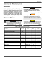
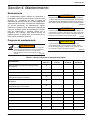
Section 4: Maintenance
Maintenance ...............................................................17
Maintenance Schedule ..............................................17
Replacing the Engine Oil ...........................................18
Checking and Replacing Auger Shear Bolts ...........19
Checking the Auger Shear Bolts ...............................19
Replacing ..................................................................19
Replacing Auger Belts ...............................................19
Replacing Traction Drive Belt ...................................20
Replacing Friction Drive Wheel ................................22
Disassembly ..............................................................22
Assembly ...................................................................24
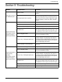
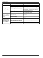
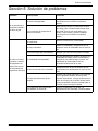
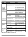
Section 5: Troubleshooting

Table of Contents
iv Owner’s Manual for Snow Blower
This page intentionally left blank.

Safety Rules & General Information
Owner’s Manual for Snow Blower 1
Section 1: Safety Rules & General Information
Introduction
Thank you for purchasing this Generac Snow Blower.
This unit has been designed to provide high-
performance, efficient operation, and years of quality use
when maintained correctly.
The Generac Snow Blower is designed and built for con-
sistent, reliable use for snow removal. It is built to with-
stand frequent handling under these conditions.
The information in this manual is accurate based on
p
roducts produced at the time of publication. The manu-
facturer reserves the right to make technical updates,
cor
rections, and product revisions at any time without
notice.
Read This Manual Thoroughly
(000100a)
Consult Manual. Read and understand manual
completely before using product. Failure to
completely understand manual and product
could result in death or serious injury.
WARNING
If any section of this manual is not understood, contact
the nearest Independent Authorized Service Dealer
(IASD) or Generac Customer Service at 1-888-436-3722
(1-888-GENERAC), or visit www.generac.com for start-
ing, operating, and servicing procedures. The owner is
r
esponsible for proper maintenance and safe use of the
unit.
SAVE THESE INSTRUCTIONS for future reference.
This
manual contains important instructions that must be fol-
lowed during placement, operation, and maintenance of
th
e unit and its components. Always supply this manual
to any individual that will use this unit, and instruct them
on how to correctly start, operate, and stop the unit in
case of emergency.
Safety Rules
The manufacturer cannot anticipate every possible cir-
cumstance that might involve a hazard. The alerts in this
ma
nual, and on tags and decals affixed to the unit, are
not all inclusive. If using a procedure, work method, or
operating technique that the manufacturer does not spe-
cifically recommend, verify that it is
safe for others and
does not render the equipment unsafe.
Throughout this publication, and on tags and decals
af
fixed to the unit, DANGER, WARNING, CAUTION, and
NOTE blocks are used to alert personnel to special
instructions about a particular operation that may be
hazardous if performed incorrectly or carelessly. Observe
them carefully. Alert definitions are as follows:
(000001)
DANGER
Indicates a hazardous situation which, if not avoided,
will result in death or serious injury.
(000002)
WARNING
Indicates a hazardous situation which, if not avoided,
could result in death or serious injury.
(000003)
CAUTION
Indicates a hazardous situation which, if not avoided,
could result in minor or moderate injury.
NOTE: Notes contain additional information important to
a procedure and will be found within the regular text of
this manual.
These safety alerts cannot eliminate the hazards that
they in
dicate. Common sense and strict compliance with
the special instructions while performing the action or
service are essential to preventing accidents.
How to Obtain Service
When the unit requires servicing or repairs, contact Gen-
erac Customer Service at 1-888-GENERAC (1-888-436-
3722) or visit www.generac.com for
assistance.
When contacting Generac Cus
tomer Service about parts
and service, always supply the complete model and
serial number of the unit as given on its data decal
located on the unit. Record the model and serial numbers
in the spaces provided on the front cover of this manual.

Safety Rules & General Information
2 Owner’s Manual for Snow Blower
General Hazards
(000722)
WARNING
Personal injury. Never use machine other than for its
designed purpose. Never overload machine. Doing so
could result in death, serious injury, and equipment or
property damage.
(000637)
WARNING
Personal injury. Do not wear loose clothing or jewelry when
operating unit. Wear protective hair covering to contain long
hair. Failure to do so could result in death, personal injury,
equipment or property damage.
(000377)
WARNING
Vision loss. Eye protection is required when
servicing unit. Failure to do so could result
in vision loss or serious injury.
Vision loss. Eye protection is required when
operating unit. Failure to wear appropriate eye
protection could result in vision loss or serious
injury.
(000407)
WARNING
(000107)
Hearing Loss. Hearing protection is
recommended when using this machine.
Failure to wear hearing protection could
result in permanant hearing loss.
WARNING
Personal injury. Only allow qualified persons to
operate unit. Operation by unqualified persons could
result in death, serious injury, property or equiment
damage.
(000421)
WARNING
(000420)
WARNING
Personal injury. Keep people and pets away from
work area. Failure to do so could result in death or
serious injury.
(000467)
Personal injury. Always verify all guards and shields are in
place prior to use. Removal or modification of guards and
shields could result in serious injury or equipment damage.
WARNING
(000721)
WARNING
Personal injury. Wear winter tread boots designed for
snow and ice traction when operating this unit. Failure
to do so could result in death or serious injury.
WARNING
Risk of injury. Do not operate or service this machine
if not fully alert. Fatigue can impair the ability to
service this equipment and could result in death or
serious injury.
(000215)
(000108)
WARNING
Hot Surfaces. When operating machine, do not
touch hot surfaces. Keep machine away from
combustibles during use. Hot surfaces could
result in severe burns or fire.
(000626)
WARNING
Personal injury. Do not operate if unit produces
abnormal noise or vibration. Doing so could result in
death, serious injury, property or equipment damage.
(000102)
WARNING
Accidental Start-up. Disconnect spark plug wire
when working on unit. Failure to do so could result
in death or serious injury.
(000620)
Personal injury. Operate only in daylight or in area lit
by artifical light. Failure to do so could result in death,
serious injury, property or equipment damage.
WARNING
WARNING
Personal injury and equipment damage. Do not
tamper with engine governed speed. Operating
engine too fast or slow increases the risk of injury
or permanent engine damage.
(000254)
(000705)
Personal injury. Never direct discharged material toward
anyone or against a wall or obstruction. Doing so could
result in death, serious injury, and equipment or property
damage.
WARNING

Safety Rules & General Information
Owner’s Manual for Snow Blower 3
Exhaust and Fuel Hazards
(000103)
Asphyxiation. Running engines produce carbon
monoxide, a colorless, odorless, poisonous
gas. Carbon monoxide, if not avoided, will
result in death or serious injury.
DANGER
(000143)
Explosion and Fire. Fuel and vapors are extremely
flammable and explosive. Store fuel in a well
ventilated area. Keep fire and spark away. Failure to
do so will result in death or serious injury.
DANGER
(000192)
DANGER
Explosion and fire. Fuel and vapors are extremely
flammable and explosive. No leakage of fuel is
permitted. Keep fire and spark away. Failure to do
so will result in death or serious injury.
(000214)
DANGER
Explosion and Fire. Do not fill fuel tank past full line.
Allow for fuel expansion. Overfilling may cause fuel
to spill onto engine causing fire or explosion, which
will result in death or serious injury.
(000174)
DANGER
Risk of fire. Allow fuel spills to completely dry
before starting engine. Failure to do so will
result in death or serious injury.
(000105)
Explosion and Fire. Fuel and vapors are extremely
flammable and explosive. Add fuel in a well
ventilated area. Keep fire and spark away. Failure
to do so will result in death or serious injury.
DANGER
WARNING
(000281)
Fire risk. Fuel and vapors are extremely
flammable. Do not operate indoors. Doing
so could result in death, serious injury, or
property or equipment damage.
(000700)
Personal Injury. When refilling, keep nozzle in contact with the
rim of the fuel tank or container until fueling is complete.
Failure to do so could result in death, serious injury, and
equipment or property damage.
WARNING
(000699)
Personal injury. Never fill equipment or container on a truck or
trailer bed. Always refill containers and equipment on the
ground. Failure to do so could result in death, serious injury,
and equipment or property damage.
WARNING
Fire Hazards
(000249)
WARNING
Risk of fire. Never operate engine without the
air cleaner installed. Operating engine without
the air cleaner could result in death or serious
injury.
(000110)
WARNING
Risk of Fire. Hot surfaces could ignite
combustibles, resulting in fire. Fire could
result in death or serious injury.
(000109)
WARNING
Risk of Fire. Verify machine has properly
cooled before installing cover and storing
machine. Hot surfaces could result in fire.
(000282)
WARNING
Explosion and fire risk. Do not smoke near unit.
Keep fire and spark away. Failure to do so could
result in death, serious injury, or property or
equipment damage.

Safety Rules & General Information
4 Owner’s Manual for Snow Blower
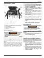
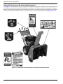
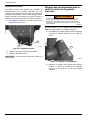
Safety and Operating Decals
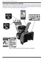
See Figure 1-1. This unit features numerous safety and operating decals. These decals provide important operating
instructions and warn of dangers and hazards. Replace damag
ed or missing safety and operating decals immediately.
Decal part numbers can be found in the unit parts manual at www.generac.com.
Figure 1-1. Safety and Operating Decal Locations

Owner’s Manual for Snow Blower 5
General Information and Setup
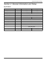
Section 2: General Information and Setup
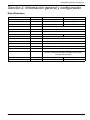
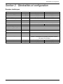
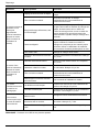
Specifications
Model Units
GC2800B GC3000B
Cleaning width in (cm) 28 (71) 30 (76)
Intake height in (cm) 21 (53) 21 (53)
Throw distance ft (m) ≤ 36
(11) ≤ 49 (15)
Starting system - 110 V Electric with recoil back-up
Transmission type - Friction disc
Speeds - 6 Forward, 2 reverse
Wheel size - 15x4.80-7 16x4.80-8
Chute rotation - Hand crank 190°
Ice chopping auger - Yes
Differential system - Auto-turn
One handed operation - Yes
Heated grips - Yes
Headlight Yes
Operator controls Shift lever, drive contr
ol, auger control, chute controls, headlight
switch, heater switch
Machine dimensions in (cm) 57 x 28 x 42 (145 x 71 x 107) 57 x 30 x 43 (145 x 76 x 109)
Machine weight lbs (kg) 227 (103) 258 (117)

6 Owner’s Manual for Snow Blower
General Information and Setup
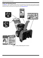
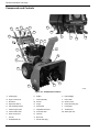
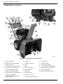
Components and Controls
B
H
I
J
G
E
011045
F
Q
P
O
A
C
D
L
M
N
R
S
T
U
AA
Z
V
W
X
Y
K
Figure 2-1. Component Locations
A Heated grips K Muffler U LED headlight
B Auger control lever L Chute assembly V Primer bulb
C Shift lever M Shovel W Choke control
D Grip heater switch N Auger X Power ON safety key
E LED head light switch O Shear bolts Y Fuel shutoff
F Chute height control P Adjustable skid shoe Z Throttle lever
G Chute rotation knob Q Pneumatic tires AA Starter pull cord
H Drive control lever R Oil drain
I Fuel fill S Belt cover
J Oil dipstick/fill cap T Electric start plug

Owner’s Manual for Snow Blower 7
General Information and Setup
Know Your Snowblower
(000100a)
Consult Manual. Read and understand manual
completely before using product. Failure to
completely understand manual and product
could result in death or serious injury.
WARNING
See Figure 2-1. Be familiar with the controls and features
of the unit prior to operation. Read this manual thor-
oughly before assembling and operating this unit. Save
this manual for
future and immediate reference.
Emissions
The United States Environmental Protection Agency (US
EPA) (and California Air Resources Board (CARB), for
engines/equipment certified to California standards)
requires this engine/equipment to comply with exhaust
and evaporative emissions standards. Locate the emis-
sions compliance decal on the engine to determine appli-
cable standards. See the included emissions warranty for
emiss
ions warranty information. Follow the maintenance
specifications in this manual to ensure the engine com-
plies with applicable emissions standards for the duration
o
f the product’s life.
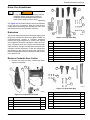
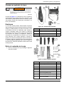
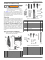
Remove Contents from Carton
1. Remove and verify the carton contains the follow-
ing prior to assembly.
A
B
011047
C
D
Figure 2-2. Components Included
Item Description QTY
A Discharge chute assembly 1
B Shifter rod assembly 1
C Handlebar assembly 1
D Parts bag 1
E
F
011048
G
H
I
K
J
L
Figure 2-3. Large Parts Bag
Item Description QTY
E Plate, adaptor 2
F Handle, shifter 2
G Bolt, M8x55 4
H Washer, 8mm ID X 22mm OD X 4
I Nut, jam, M8 4
J Key, shear bolt, and spark plug tool bag 1
K Cable tie, 7-1/2 in L 5
L Chute hardware and shear bolts 1
M
N
P
Q
O
R
011049
Figure 2-4. Small Parts Bag
Item Description QTY
M Key, off switch 2
N Tool, spark plug 1
O Nut, jam, M8 2
P Bolt, shear, auger 2
Q Nut, Hex Lock, M8-1.25 3
R Bolt, Carriage, M8-1.25 X 16MM 3

8 Owner’s Manual for Snow Blower
General Information and Setup
2. Contact Generac Customer Service at 1-888-436-
3722 (1-888-GENERAC), or www.generac.com
with the unit model and serial number for any miss-
ing carton contents.
3. Recor
d model, serial number, and date of pur-
chase on front cover of this manual.
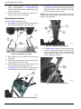
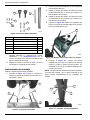
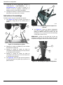
Assembly Instructions
Proceed as follows to assemble unit:
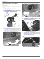
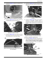
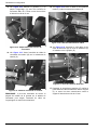
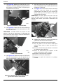
1. See Figure 2-5. Position handlebar assembly (A)
behind snow blower (B) in a flat, clean area.
B
A
C
D
E
F
011052
Figure 2-5. Handlebar Assembly
2. Mo
ve plastic covers (C) away from cable spring
hooks (D).
3. Atta
ch cable spring hook of drive control cable (E)
into pulley wire on left side of unit.
4. Atta
ch spring hook of auger control cable (F) into
the tension connector on right side of unit.
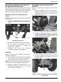
5. See Figure 2-6. Have a helper hold upper handle-
bar assembly in position on lower handlebar (G).
G
011051
Figure 2-6. Upper and Lower Handlebar Assembly
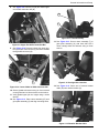
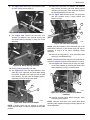
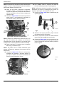
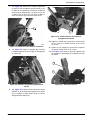
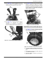
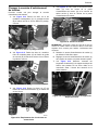
6. See Figure 2-7. Place adaptor plates (H) between
upper and lower handlebar assemblies and secure
with
M8 X 55 bolts, 8 X 22 X 2 washers (J) and M8
jam nuts (K) using a 13mm wrench.
NOTE: V
erify bolt heads are on the outside of the han-
dlebar and the square portion of the bolts go fully into the
sq
uares in the handlebar.
I
011053
H
J
K
Figure 2-7. Adaptor Plate Assembly
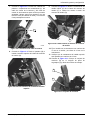
7. See Figure 2-8. Lift plastic covers and inspect jam
nuts (L) on auger control cable and drive control
cabl
e to verify tightness. Tighten as needed using
a 6mm wrench to hold the cable and an 8mm
wrench to tighten the jam nut.
L
011054
Figure 2-8. Control Cable Jam Nut

Owner’s Manual for Snow Blower 9
General Information and Setup
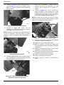
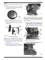
8. See Figure 2-9. Remove pin (M) and install upper
end of shift connection bar (N).
M
011055
N
Figure 2-9. Upper End Shift Connection Bar
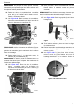
9. See Figure 2-10. Remove locknut from lower
gim-
bal (O) of shift connector bar (P) and insert threads
th
rough shift connector (Q).
O
011056
Q
P
Figure 2-10. Lower Gimbal of Shift Connector Bar
10. Se
cure gimbal with locknut using an 11mm wrench
on the gimbal and a 13mm wrench on the locknut.
11. V
erify gimbal upper jam nut is tight using a 14mm
wrench.
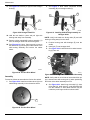
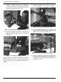
12. See Figure 2-11. Place chute assembly (R) onto
gear plate assembly (S) and align mounting holes.
R
011057
S
Figure 2-11. Chute Assembly
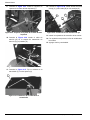
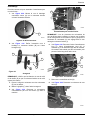
13. See Figure 2-12. Secure chute assembly (T) to
gear plate assembly (U) with three M8-1.25 X
16
mm carriage bolts and locknuts using a 13mm
wrench.
T
011058
U
Figure 2-12. Carriage Bolt Locations
14. See Figure 2-13. Screw end of rotation bracket
cable (W) onto rotation bracket (X).
X
011059
W
Figure 2-13. Rotation Bracket Cable

10 Owner’s Manual for Snow Blower
General Information and Setup
NOTE: It may be necessary to turn chute rotation handle
on control panel to align the cable end with the worm
gear in the bracket.
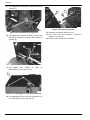
15. See Figure 2-14. Place rotation bracket cable (Y)
into connecting plate (Z).
011060
Y
Z
Figure 2-14. Rotation Bracket Cable
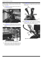
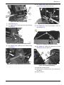
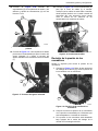
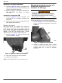
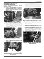
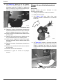
16. See Figure 2-15. Install eyelet end (A) of deflector
cable (B) onto deflector lever (C) and secure with
p
in (D).
011061
B
E
F
A
TC
D
Figure 2-15. Deflector Cable Installation
17. L
oosen top jam nut (E), slide threaded portion of
deflector cable into bracket (F) and tighten two jam
nuts against bracket using two 13mm wrenches.
18. See Figure 2-16. Screw handles (G) onto shift and
deflector levers, and tighten jam nuts (H) using a
17
mm wrench.
011062
H
G
Figure 2-16. Lever Handles Installation
19. See Figure 2-17. Use wire cutters to cut cable tie
securing heated grip connector (I) and insert
he
ated grip connector into harness plug (J).
011063
I
J
Figure 2-17. Heated Grip Connector

Owner’s Manual for Snow Blower 11
General Information and Setup
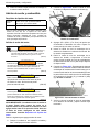
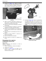
20. See Figure 2-18. Install cable ties (K) to secure
wire harness (L) to handlebar. Verify cables are not
on
top of handlebar, where they can interfere with
starter pull cord (M). Wear eye protection when
cutting excess ends of cable ties using wire cutters.
011065
K
M
L
Figure 2-18. Install Cable Ties
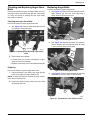
Checking Tire Pressure
Proceed as follows to check tire pressure:
1. See Figure 2-19. Remove valve stem protective
cap (A) and check tire pressure with a tire pressure
g
auge.
011067
A
Figure 2-19. Checking Tire Pressure
2. Com
pare tire pressure reading with manufacturer's
recommended tire pressure stamped on the side of
the tire.
3. If
tire pressure is too low, add air through valve
stem with an air hose.
4. Re
place valve stem protective cap when finished.
Adding Oil and Fuel
Engine Fluid Requirements
Engine Oil*
Above -30 °F (-34 °C): 5W-30 or 0W-30
-13 °F (-25 °C) or below: 0W-30
Fuel Unleaded gasoline. Minimum 85 octane rating.
* Use only high detergent oil classified “For service SF, SG, SH,
SJ” o
r higher. Do not use special additives. See engine
owner’s manual for detailed engine information, including oil
and fuel quantities and cold temperature oil specifications.
Adding Engine Oil
WARNING
(000341)
Fire and explosion risk. Keep spark and flame
away from liquid and vapor. Do not smoke while
using. Doing so could result in death, serious
injury, or equipment damage.
(000210)
WARNING
Skin irritation. Avoid prolonged or repeated contact with
used motor oil. Used motor oil has been shown to cause
skin cancer in laboratory animals. Thoroughly wash
exposed areas with soap and water.
(000135)
Engine damage. Verify proper type and quantity of
engine oil prior to starting engine. Failure to do so
could result in engine damage.
CAUTION
(000419)
CAUTION
Personal injury. Wear appropriate personal protective
equipment at all times while operating and servicing
unit. Failure to do so could result in personal injury.
IMPORTANT NOTE: The unit is shipped without oil in
engine. Traces of oil may be in reservoir from factory
testing. Oil must be added prior to initial operation.
Use only the recommended high detergent engine
oil. See Engine Fluid Requirements.
Proceed as follows to add engine oil:
1. Place un
it on a firm, level surface. Verify engine is
cooled.

12 Owner’s Manual for Snow Blower
General Information and Setup
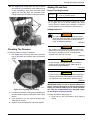
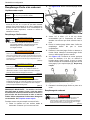
2. See Figure 2-20. Remove oil dipstick/fill cap (A).
A
011069
Figure 2-20. Oil Dipstick and Fuel Fill
3. Add
17–20 oz (0.5–0.59 L) of oil recommended by
engine manufacturer. Wait one minute for oil to set-
tle.
4. Insert oil dipstic
k/fill cap into oil fill. Do not screw it
on completely.
5. Remove oil dipstick/fill cap and inspect
oil level.
Clean oil dipstick/fill cap with a clean rag after
inspecting.
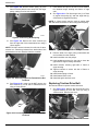
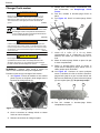
6. See Figure 2-21. Continue adding a few ounces at
a time, checking the oil dipstic
k/fill cap until oil level
is in hatched area (B) between the bottom of the oil
dipstick/fill cap (C) and H(igh) mark (D). Do not
overfill.
B
011070
D
C
Figure 2-21. Oil Fill Line
7. Replace the oil
dipstick/fill cap and tighten when
complete.
Adding Fuel
(000105)
Explosion and Fire. Fuel and vapors are extremely
flammable and explosive. Add fuel in a well
ventilated area. Keep fire and spark away. Failure
to do so will result in death or serious injury.
DANGER
(000214)
DANGER
Explosion and Fire. Do not fill fuel tank past full line.
Allow for fuel expansion. Overfilling may cause fuel
to spill onto engine causing fire or explosion, which
will result in death or serious injury.
WARNING
Explosion and Fire. Do not smoke while
refueling unit. Failure to do so could result in
death, serious injury, or property or equipment
damage.
(000284a)
NOTE: The unit is shipped without fuel. Fuel must be
added prior to first starting attempt.
Proceed as follows to add fuel:
1. Place un
it on a firm, level surface. Verify engine is
cooled.
2. See Figure 2-22. Remove fuel fill cap (A).
A
011069
Figure 2-22. Fuel Fill Cap
3. Fill tank w
ith fresh, unleaded fuel with a minimum
85 octane rating to 1–1.5 in (25.4–38.1 mm) below
top of the fill neck to allow for fuel expansion. Do
not overfill.
4. Install fuel fill
cap. Secure tightly.

Owner’s Manual for Snow Blower 13
Operation
Section 3: Operation
Operation and Use Questions
Call Generac Customer Service at 1-888-GENERAC (1-
888-436-3722) with questions or concerns about unit
operation and maintenance.
Before Starting Engine
(000100a)
Consult Manual. Read and understand manual
completely before using product. Failure to
completely understand manual and product
could result in death or serious injury.
WARNING
WARNING
Equipment damage. Do not attempt to start or operate
a unit in need of repair or scheduled maintenance.
Doing so could result in serious injury, death, or
equipment failure or damage.
(000291)
IMPORTANT NOTE: Unit is shipped without oil. Add
engine oil before starting. See Adding Engine Oil for
instructions.
Perform the following before starting engine:
1. Chec
k engine oil level.
2. Chec
k fuel level.
3. Inspec
t unit for damage.
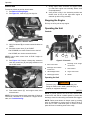
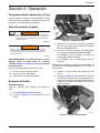
Starting the Engine
NOTE: The engine has a fixed throttle position and is
equipped with an auto-choke. No throttle or choke adjust-
ment by the operator is required.
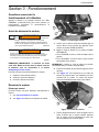
Manual Start
1. See Before Starting Engine.
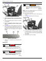
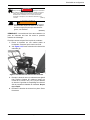
2. See Figure 3-1. Insert key (A) into key s
lot.
B
011071
A
C
D
Figure 3-1. Manual Start
3. V
erify fuel shutoff (B) is turned counterclockwise to
OPEN.
4. Set ch
oke control lever (C) to CHOKE:
• On GC2800B, turn choke control lever left.
• On GC300B, turn choke counterclockwise.
NOTE: Leave chok
e control lever in RUN if engine is
already warm.
5. Pu
sh and release primer bulb (D) three times.
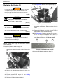
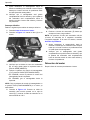
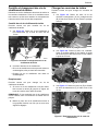
6. See Figure 3-2. Slowly pull starter cord (E) until
resistance is felt, then pull starter cord rapidly.
Starter cord
will recoil back into position when
released.
E
011073
Figure 3-2. Starter Cord
7. Slowly ad
just choke clockwise as the engine
warms up. Wait until engine runs smoothly before
each choke adjustment.
8. V
erify choke is turned fully clockwise, and throttle
lever is fully to the right when engine is warmed up
and running smoothly.

14 Owner’s Manual for Snow Blower
Operation
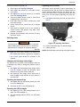
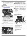
Electric Start
Proceed as follows to perform electric start:
1. See Before Starting Engine.
2. See Figure 3-3. Insert key (A) into key s
lot.
011071
A
C
B
Figure 3-3. Electric Start
3. V
erify fuel shutoff (B) is turned counterclockwise to
OPEN.
4. Set choke cont
rol lever (C) to CHOKE:
• On GC2800B, turn choke control lever to the left.
• On GC300B, turn choke counterclockwise.
NOTE: Leav
e choke control lever in RUN if engine is
already warm.
5. See Figure 3-4. Connect a heavy-duty extension
cord into control box (D) and plug extension cord
int
o a 120V outlet.
011072
D
E
Figure 3-4. Control Box and Starter Button
6. Push
starter button (E) until engine starts, then
release button.
NOTE: Do
not push starter button more than 10 times at
intervals of 5 seconds on, 5 seconds off. If engine will not
start, see Troubleshooting.
7. Slo
wly adjust choke clockwise as engine warms
up. Wait until engine runs smoothly before each
choke adjustment.
8. V
erify choke is fully in the clockwise position and
throttle lever is fully to the right when engine is
warmed up and running smoothly.
Stopping the Engine
Pull key out of key slot to stop engine.
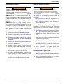
Operating the Unit
Controls
011075
F
G
H
A
C
D
B
E
Figure 3-5. Controls
A Drive control lever E
Discharge chute height
control leve
r
B
Discharge chute rotation
control lever
F Gear selector
C LED headlight switch G Auger control lever
D Heated grips switch H Handle
Operating the Unit
(000724)
WARNING
Personal injury. Never use unit as a snow plow.
Doing so could result in death, personal injury, or
property or equipment damage.
NOTE: If ground speed of unit is too fast, release drive
control lever and shift to a slower speed to prevent the
discharge chute from becoming overloaded and clogged.
NOTE: Ra
ise snow thrower in deeper snow by pushing
down on handlebars to remove some of the top layer of
snow first, or take a half-width pass. A second or third
pass will remove remaining snow more easily.

Owner’s Manual for Snow Blower 15
Operation
Proceed as follows to operate unit:
1. Star
t engine. See Starting the Engine.
2. Aft
er engine has warmed up, set throttle to maxi-
mum speed.
3. See Figure 3-5. Set gear selector (F) to desired
gear. See Selecting Gears.
4. V
erify snow blower auger is clear of snow before
engaging auger control lever.
5. Push
auger lever (G) down to handle (H) to start
snow blower auger.
6. Gently squ
eeze drive control lever (A) to engage
wheels.
7. Allo
w auger to operate for one to two minutes to
remove buildup and prevent icing when snow
removal is complete.
8. Rele
ase drive and auger levers and pull out key to
shut down engine.
Selecting Gears
(000726)
Personal injury. Verify drive control lever is released
before shifting gears. Failure to do so could result in
personal injury, or property or equipment damage.
WARNING
See Figure 3-5. Gear selector allows for the selection of:
• Six forward gears labeled 1 (slowest) to 6 (fastest).
• Two reverse gears labeled R1 (slowest) to R2
(fastest).
Changing the Discharge Chute Angle
The angle of the top portion of the discharge chute can
be adjusted up or down to change the distance snow is
thrown.
1. See Figure 3-5. Set discharge chute height control
lever (E) forward to lower the discharge chute
d
eflector to blow snow shorter distances.
2. Set d
ischarge chute height control lever back to
raise discharge chute deflector to blow snow lon-
ger distances.
Operating the Heated Grips
1. See Figure 3-5. Set heated grips switch (D) to ON
to turn on heated grips.
2. Set sw
itch to OFF to turn off heated grips.
Operating the LED Headlight
1. See Figure 3-5. Set LED headlight switch (C) to
ON to turn LED headlight on.
2. Set LED hea
dlight switch to OFF to turn LED head-
light off.
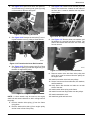
Adjusting the Skid Shoes
Skid shoes can be adjusted to improve performance on
the desired surface. Set skid shoes to lowest position for
smooth pavement without defects. For gravel type sur-
faces, raise skid shoes to a he
ight which allows the most
snow to be removed without disturbing the gravel sur-
face.
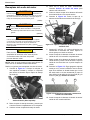
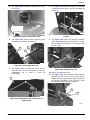
1. See Figure 3-6. Loosen jam nuts (A) using a 1/2 in
wrench.
011096
A
B
Figure 3-6. Adjusting Skid Plates
2. Position skid sh
oes (B) to the desired height.
3. T
ighten jam nuts.
NOTE: Bot
h skid shoes must be set at the same height.

16 Owner’s Manual for Snow Blower
Operation
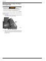
Removing Clogs in Auger Housing or
Discharge Chute
(000727)
WARNING
Personal injury. Before performing any maintenance
procedure or inspection, stop the engine, remove key, and
allow unit to cool. Failure to do so could result in death,
personal injury, or property or equipment damage.
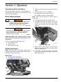
Proceed as follows to remove clogs in auger housing or
discharge chute:
1. See Figure 3-7. Use shovel (A) to clean snow from
discharge chute or auger housing.
011097
A
Figure 3-7. Clearing Clog
2. Star
t unit to clean out any remaining material and
repeat cleaning process as needed until snow dis-
charges freely.
La page charge ...
La page charge ...
La page charge ...
La page charge ...
La page charge ...
La page charge ...
La page charge ...
La page charge ...
La page charge ...
La page charge ...
La page charge ...
La page charge ...
La page charge ...
La page charge ...
La page charge ...
La page charge ...
La page charge ...
La page charge ...
La page charge ...
La page charge ...
La page charge ...
La page charge ...
La page charge ...
La page charge ...
La page charge ...
La page charge ...
La page charge ...
La page charge ...
La page charge ...
La page charge ...
La page charge ...
La page charge ...
La page charge ...
La page charge ...
La page charge ...
La page charge ...
La page charge ...
La page charge ...
La page charge ...
La page charge ...
La page charge ...
La page charge ...
La page charge ...
La page charge ...
La page charge ...
La page charge ...
La page charge ...
La page charge ...
La page charge ...
La page charge ...
La page charge ...
La page charge ...
La page charge ...
La page charge ...
La page charge ...
La page charge ...
La page charge ...
La page charge ...
La page charge ...
La page charge ...
La page charge ...
La page charge ...
La page charge ...
La page charge ...
La page charge ...
La page charge ...
La page charge ...
La page charge ...
La page charge ...
La page charge ...
La page charge ...
La page charge ...
La page charge ...
La page charge ...
La page charge ...
La page charge ...
La page charge ...
La page charge ...
La page charge ...
La page charge ...
La page charge ...
La page charge ...
La page charge ...
La page charge ...
La page charge ...
La page charge ...
La page charge ...
La page charge ...
-
 1
1
-
 2
2
-
 3
3
-
 4
4
-
 5
5
-
 6
6
-
 7
7
-
 8
8
-
 9
9
-
 10
10
-
 11
11
-
 12
12
-
 13
13
-
 14
14
-
 15
15
-
 16
16
-
 17
17
-
 18
18
-
 19
19
-
 20
20
-
 21
21
-
 22
22
-
 23
23
-
 24
24
-
 25
25
-
 26
26
-
 27
27
-
 28
28
-
 29
29
-
 30
30
-
 31
31
-
 32
32
-
 33
33
-
 34
34
-
 35
35
-
 36
36
-
 37
37
-
 38
38
-
 39
39
-
 40
40
-
 41
41
-
 42
42
-
 43
43
-
 44
44
-
 45
45
-
 46
46
-
 47
47
-
 48
48
-
 49
49
-
 50
50
-
 51
51
-
 52
52
-
 53
53
-
 54
54
-
 55
55
-
 56
56
-
 57
57
-
 58
58
-
 59
59
-
 60
60
-
 61
61
-
 62
62
-
 63
63
-
 64
64
-
 65
65
-
 66
66
-
 67
67
-
 68
68
-
 69
69
-
 70
70
-
 71
71
-
 72
72
-
 73
73
-
 74
74
-
 75
75
-
 76
76
-
 77
77
-
 78
78
-
 79
79
-
 80
80
-
 81
81
-
 82
82
-
 83
83
-
 84
84
-
 85
85
-
 86
86
-
 87
87
-
 88
88
-
 89
89
-
 90
90
-
 91
91
-
 92
92
-
 93
93
-
 94
94
-
 95
95
-
 96
96
-
 97
97
-
 98
98
-
 99
99
-
 100
100
-
 101
101
-
 102
102
-
 103
103
-
 104
104
-
 105
105
-
 106
106
-
 107
107
-
 108
108


Generac SB15130GENG Le manuel du propriétaire
- Catégorie
- Souffleuses à neige
- Taper
- Le manuel du propriétaire
- Ce manuel convient également à
dans d''autres langues
Autres documents
-
Simplicity 1696555-00 Manuel utilisateur
-
Ariens 921031 Manuel utilisateur
-
-
-
-
-
Simplicity 1695386 Manuel utilisateur
-
-
Simplicity 1696668-00 Manuel utilisateur
-